Source:
Challenging Glass 7
Conference on Architectural and Structural Applications of Glass
Belis, Bos & Louter (Eds.), Ghent University, September 2020.
Copyright © with the authors. All rights reserved.
ISBN 978-94-6366-296-3, https://doi.org/10.7480/cgc.7.4429
Authors:
Roman Schieber - Knippers Helbig GmbH
Florian Meier - Knippers Helbig Inc.

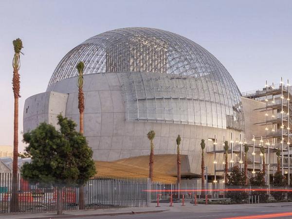
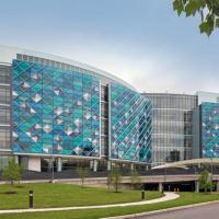
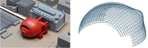
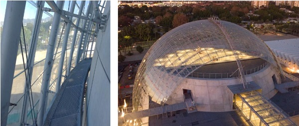
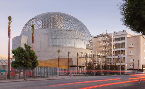
The 388 Mio USD project consist of a six story tall renovated existing building and a dome-shaped iconic new building housing a 1,000-seat theater. Both buildings are linked by several – partially suspended – bridges. The150 ft (ca. 45m) diameter dome is a steel grid shell with cable bracing and flat, shingled glass panels on a secondary layer.
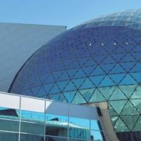
The single-layered curved structural steel tubes have a diameter of 4 inches only. With an airy and weightless quality, the globe’s structure seems to dissolve into the background. The construction of the steel glass structure was completed in autumn 2019. Knippers Helbig was responsible for design and engineering of the structure and glazing system of spherical glazed gridshell structure from concept stage until signed and sealed drawings and calculations and was responsible for design and engineering of the bridges during Design Development.
1.Introduction
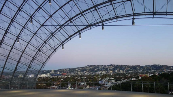
The Academy Museum of Motion Pictures will celebrate the artistry and technology of film, becoming the world’s first museum and event space devoted to the motion picture. Totaling 290,000 square feet(ca. 27.000 m²), the project consists of a six-story tall renovated building, formerly known as May Co. department store, and a dome-shaped new building housing a 1,000-seat theater. Above the theater, the so-called Dolby terrace covered under a spectacular, 150 ft (ca. 45m) wide spanning steel and glass dome and architectural centerpiece of the building, will be used for events and special exhibitions.
Both buildings are linked by several –partially suspended –bridges. Together with design architect Renzo Piano Building Workshop (RPBW) and executive architect Gensler, Knippers Helbig (KH) developed the structure and glazing system of spherical glazed gridshell structure through all design phases. The dome structure is a steel grid shell with cable bracing and flat, shingled glass panels on a secondary layer. KH also designed concepts for the four bridges between the dome and the adjacent building throughout DD phase.
2.Concepts and Geometric Principles
The glass dome was developed in close collaboration with design architect RPBW of Genoa, Italy. The canopy primarily needed to provide weather protection for the terrace and was initially designed as a closed glass sphere. It was later on transformed to a half sphere with generous openings towards the south and north, allowing for an undisturbed view at the nearby Hollywood Hills.
When KH was awarded the contract to take over and carry out the design of the dome throughout all phases, the goal was to lighten up the visual appearance of the main structure. KH suggested to move from the previously designed spatial frame to a highly optimized, single layer grid shell. From the first sketches to the finalized structure, KH was able to realize a 4” (100 mm) diameter round HSS section for the main arches of the dome, which led to the seemingly weightless design of the dome.
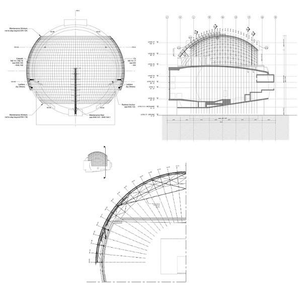
Besides the main structure, many other elements needed to be coordinated such as a layer of glazing for weather protection, connection brackets for shading elements at the inside of the dome, sprinkler pipes and electronic conduits, heavy anchors to support future exhibition items and maintenance stairs, catwalks and tie-off anchors.
The overall geometry of the glass dome follows an exact 150 ft. diameter sphere. The terrace is about 76 feet above ground, the glass dome’s apex is about 120 feet high. The openings at the south are about 11 feet high, in the north about 22 feet. The bottom half of the sphere is cut off; however, it still overlaps partially with the supporting reinforced concrete structure of the Geffen theatre, which creates the bottom half of the sphere. At the area of the overlap, the steel/glass dome leaves a gap to the exposed precast panels, and several pins are employed to stabilize and provide support to the EW-arches. The screen-box and projector-box of the cinema are visible from the outside, as they protrude the sphere.
2.1.Structural Members
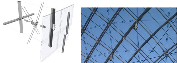
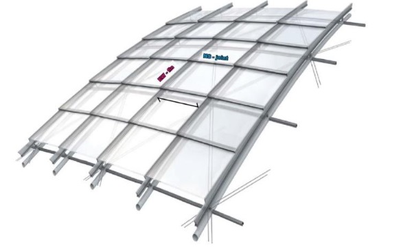
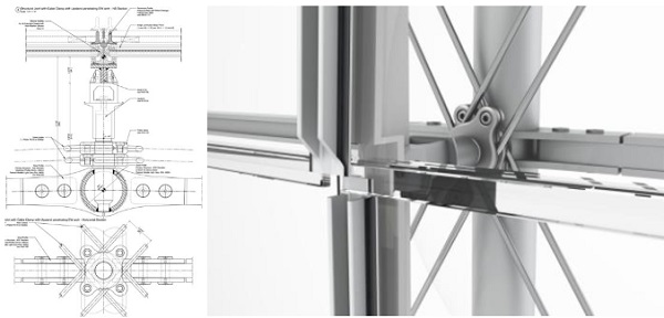
The primary structure of the steel grid shell itself consists of 4” (100mm) diameter round HSS arches in east-west direction. The arches are oriented parallel to each other in plan and spaced at 4 feet OC. In north-south direction, the radially oriented arches (NS-arches) are made of custom solid rectangular sections and are intersecting with the east-west arches perpendicular at every node. The resulting quadrilateral grid structure is furthermore braced (“cross bracing”) to provide in-plane stiffness. The 10 mm diameter twin cables are running diagonally over the entire dome and are clamped at every node of the grid.
2.2.Glazing
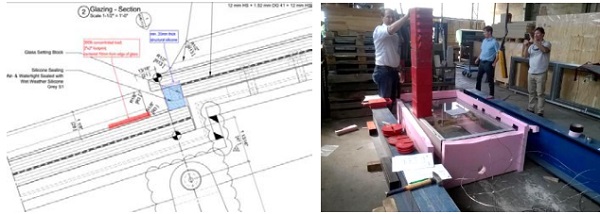
Secondary T-shaped profiles are running approx. 10” above the primary east-west structure and serve as a support for the glazing panels. The secondary structure is supported on upstands that occur at each intersection between the EW-arches and the NS-arches. The upstands are radial to the sphere and serve as support for the cable clamps. This structural build-up is illustrated in the figures below. The glazing consists of flat, laminated glass made of two 12mm glass panes. All panels vary in size due to the changing dimension of the quadrilateral grid. The signature shingled appearance of the glazing is created by stepping the top side of the T section. The glass panels overlap each other slightly at every step.
3.Global Structural Behaviour
Oriented strictly in east-west direction, the round HSS arches are the main load carrying elements. They transfer the loads of the dome all the way to the embed connections to the concrete dome. The north-south oriented transvers members are connecting the individual arches together. While the outside diameter of the continuous east-west arches remains the same, the wall thickness was adjusted towards the north and south opening to account for higher internal forces. The north-south struts are all sized equally throughout the structure according to the governing load combination.
Thekey component for the structural integrity of the shell are the twin cables which run diagonally across the dome and avoid any in-plane rhombic distortion of the dome. The structural design was developed, analyzed and optimized in an iterative manner using various cable pretension values to make sure the structure is perfectly tuned. One of the challenges of the pretension is to have sufficient pretension in all cables after completing all phases of construction, since the initial tensioning of the cables if performed while the structure is still on scaffolding.
Although the project is based in California, seismic acceleration was less of a concern thanks to the base isolated construction of the entire dome sphere. The structural design of a lightweight steel grid shell is usually most sensitive to wind effects. Therefore, the shell was tested in a wind laboratory and the results were used for the structural analysis. In terms of dead load, an analysis of the individual masses showed that the glass weight is significantly higher than the weight of the steel structure. This is mostly due to the thick glass panes. The glass panes had to be designed strong enough to support maintenance personnel.
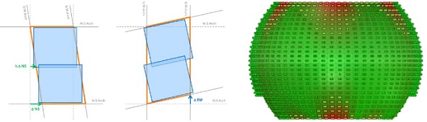
When analyzing the design using 3rd order theory in the structural analysis software SOFiSTiK, the engineers at Knippers Helbig found that the shell was globally behaving very stiff, but the large openings towards the north and the south of the shell however created the largest deflections and stresses. When introducing a diagonal bracing system, named internally after the Russian engineer Vladimir Shukhov (1853-1939), at both openings, the deflections and stresses could be sufficiently controlled.
4.Detailing
4.1.Dome Support
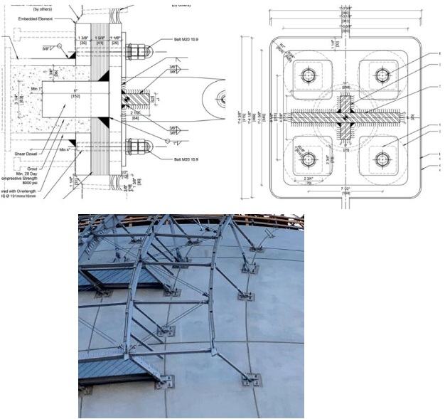
When connecting to the reinforced concrete dome, the construction tolerances and long-term deflections of the concrete sphere had to be compensated. The concrete dome was designed by a different engineering team and was executed by another contractor. Therefore, KH and Gartner, the glass dome specialty contractor, developed a connection detail with generous adjustability in all axes. On site, an as-built survey showed that the reinforced concrete dome had moved much further than initially expected by the base building engineer. Therefore, engineers at KH and Josef Gartner adjusted the glass dome’s global position to follow the movement of the reinforced concrete dome.
In terms of forces, the embed detail had to be robust enough to transfer the compression and tension forces of the support strut. Since the geometrical layout of the dome created many different angles due to the strict east-west orientation of the struts, some of the embeds towards the north and south of the dome, where the spherical geometry created sharp angles, substantial shear forces had to be anchored to the dome as well by means of a solid shear studs. Also, the diagonal support compression struts and the lateral bracing rods created such tangential forces.
4.2.Steel
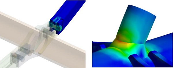
Besides the connection to the dome, little tolerance adjustment needed to be considered for the remaining structure. The typical connections of the continuous arches to the connecting struts are precisely fabricated and therefore are supposed to fit perfectly on site. The two bolts connecting the struts to the arch transfer primarily axial forces and out-of-plane bending moments, as the diagonal cross bracing is preventing any rhombic distortion and therefore minimizes in-plane rotation and bending of the strut connection.
When connecting to the arch, the two fin plates hug the round HSS and act as a stiffener. Not only forces from the two struts are introduced to the round HSS, but also considerable forces from the upstand that not only supports the T shaped substructure of the glazing, but also functions as the anchor for the cross bracing cables via cable clamps.
The upstand is designed to have certain degrees of freedom, therefore limiting the forces that are transferred from the glazing substructure to the primary structure (the intention was that the secondary structure is not contributing to the global structural system), and it also has an adjustability (up and down) in order to precisely located the glazing support in out-of-plane direction.
4.3.Glazing
The architectural target was to design a transparent and light weight glazing system on top of the structural steel layer. The shingled planar glass panes are supported by curved 60mm wide steel T-profiles in east-west direction; means the glass is basically 2-side supported.
The vertical pins between the structural steel layer and glass framing are designed to accommodate tolerances perpendicular to the glass surface with an internal thread. In plane of the glass the glazing system was designed for zero-tolerances. This was achieved by prefabricating the steel shell and glazing system in ladder frames and checking the geometry with templates during fabrication and installation.
The glazing system was designed with a frame bite of 15mm what required careful investigation and limitation of all kind of structural movements, especially rhombic distortion effects. The glass makeup consists of two 12mm low iron glass lites with a Saflex DG41 interlayer. Only one of both glass panes was dead-load-supported, what means that the outer glass lite was only supported through the interlayer. All laminated glass panes are stepped at the lower edge to allow for a hidden dead-load support.
Due to the architectural desire of a highly transparent glazing, solar control coatings had to be avoided. In order to achieve a high comfort (temperatures) on the terrace under the glazing, roller shades as well as operable vents were integrated into the system.
5.Maintenance Structures
The requirement for maintenance of the glazing, such as window washing, asked for a special solution in order to allow workers for access the entire dome surface. Whereas most of the inside surface of the dome can be easily cleaned using conventional maintenance platforms and man-lifts, the portion of the interior dome overlapping with the concrete dome on the east and west side and the entire external surface of the glazing required alternative approaches.
The solution, which was developed in close coordination with the design team and maintenance consultants, was an interior catwalk, running between glazing and precast concrete of the dome, andan exterior a maintenance stair, leading to the apex of the dome. The stair became one of the main design features of the dome. Workers can tie off from the stair’s uppermost platform with designated man rated anchors. With help of the additional features, the workers are able to reach every corner of the glass surface.
6.Testing
6.1.Glazing
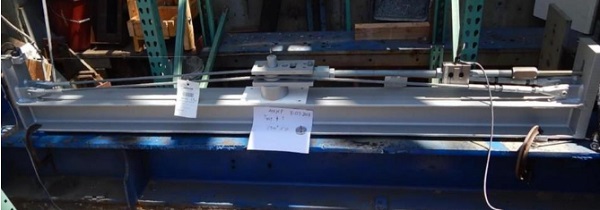
The frame bite of 14 mm and the dead load support system of the glass panes in general had to be confirmed with some racking tests. The structural analysis predicted a worst-case distortion of 27.1 mm in North-South direction and 8.4 mm in East-West direction.
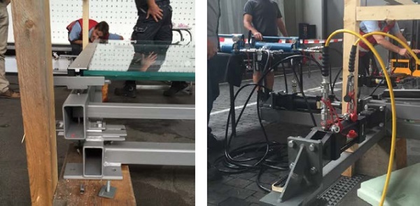
A mockup consisting of 4 glass panes with actual details mounted on a flexible subframe was build and distorted in 2 directions with hydraulic jacks. The distortion was increased in 5mm steps up to 70 mm in both directions. As a result no failure of any kind was found up to the max. distortion which was ~2.5 times greater than predicted in the structural analysis.
As the glass panes are basically only supported on two sides and glass had to be designed as accessible for maintenance and cleaning, design criteria similar than outlined in ASTM E 2751 have been chosen. The glass analysis showed that some load cases were close to the limits; so another small mockup has been build simulating a worst case maintenance load case.
One representative glass pane with a makeup of 2*12 mm HS glass and a 1.52mm DG41 interlayer was installed with actual project details on a sub frame; temperature was increased to 50°C and kept on that level for the entire test. Loads were applied at the most critical location on a surface area of 4 in²; loading was increased from 50lbs to 300lbs and kept for 10 minutes.
When no failure of any kind was discovered, the test has been repeated a) with a broken upper glass bane and b) with a broken upper and a broken lower glass pane. As a result the cracks in the glass basically had no visible impact on the performance of the glass; no major deflection etc. have been discovered. When all tests have been passed the loading was further increased to 825 lbs – when the weights tumbled over and massively damaged the glass. However it was found that no weights fell through the glass and no harmful glass parts fell out of the laminate.
6.2.Cable Clamps
The diagonal twin cables of the dome structure are clamped each time they pass a node of the primary dome structure. The individual segments of the cables will receive uniform pre-tension during installation, but as soon as the scaffolding is released, and especially in wind scenarios, parts of the dome geometry are deforming in a rhombic shape, explained in the section above.
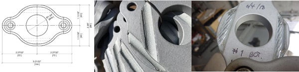
The diagonal twin cables, which counteract this rhombic distortion, will receive increased axial tension forces at areas of the dome where the structure deforms most. This creates changing cable forces from one segment to the other. The differential value of tensile force is carried by the cable clamp. The clamps are therefore an essential member of the structural system.
Cable clamps work through the mechanical principle of friction. The pressure on the cable clamp is created by two pre-tensioned M12 bolts. The bolt pretension and the friction coefficient are the main factors to achieve high performance clamps. Since the friction value can’t be exactly determined by theoretical analysis, tests are obligatory to confirm the friction value in every specific case of application. The friction coefficient in the cable clamps can be improved by considering certain rules in design and fabrication of clamps.
Furthermore, design considerations must be considered to maintain the structural integrity of the cable when applying pressure. A notch on both sides of the clamp allows the cable to be guided during assembly and when in service. The notched steel is the most important part and needs special attention as the pressure should be applied on the cable in a distributed manner. This avoids that the cable structure is damaged due to high local pressures.
The diameter of the notched steel must be determined as precise as 0.1 mm. Also, the start and end of the notched steel have a so-called ‘trumpet’, a clothoidical widening of the notch-diameter to allow a smooth transition from clamped (and therefore reduced cable diameter) to the non-clamped zone of the cable. The clamps are high strength steel pieces which are formed by a drop-forging process.
After being manufactured, the clamps receive a zinc coating at the notched portion of the steel and the typical coating for the remaining surfaces. The zinc gives a rough surface on the one hand, and on the other hand the cable wires are protected by the comparably soft zinc layer and will leave visible traces in the zinc coating when prestressed.
When tested, the cable is anchored on both ends of the testing apparatus and remains in position. The clamp is attached to the twin cables, and once pretensioned, will be pulled by a hydraulic cylinder. The test is performed in a force-controlled procedure, the force is applied in iterations, including waiting times, until an abrupt slippage of the cable clamp can be monitored.
7.Fabrication and installation
7.1.Primary structure
Permasteelisa North America / Josef Gartner (JG) was the specialty façade contractor for the project. The design by Renzo Piano Building Workshop and Knippers Helbig was further optimized and adjusted in coordination with JG. Through intense coordination, the team was able to avoid an increase of the initially estimated cost with only little variations, at the same time maintain the architectural intent and improve the technical concept of the structure.
One of the main goals during manufacturing was to maintain the tight tolerance requirements of the global structure. The structure was assembled in the shop on a template representing a portion of the dome. This assured that the assembled pieces create exactly the final geometry when assembled on site. The pieces were manufactured using several technologies, mostly by conventional welding of flat steel plates, partially by CNC-milling, some of the pieces were fabricated using drop-forging, such as the cable clamp or the cable end fitting detail.
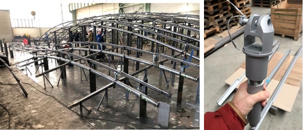
On site, the steel pieces arrived in so-called ladder frames, which means that 2 parallel arch segments were already pre-assembled, including the connecting north-south struts, and the secondary steel structure. This simplified shipping, handling and installation. After placing the primary structure (and attached secondary framing) on a scaffolding, the individual segments were joined using an internal pre-tensioned connection in the arches, and the typical bolted connection for the north-south struts.
The remaining element of the structural system, the diagonal twin cables, were installed and fully pre-tensioned. After interconnecting the ladder frames and connecting the structure to the installed embed connections, and final inspection of the cable pretension, the supporting posts of the scaffolding were carefully removed, so that the structure spans free.
7.2.Glazing
The shingled glazing was installed in a specific order, carefully balancing the additional weight and avoid non-uniform loading. The self-weight of the glass panes adds the most weight to the structure and is much heavier than the supporting steel structure itself.
8.Summary
When finished in summer 2019, the spherical steel and glass dome of the Academy Museum of Motion pictures will be the centerpiece of the highly anticipated museum on Wilshire Boulevard and one of the most spectacular examples of lightweight architecture in America.
9.Acknowledgments
The authors wish to acknowledge key personnel who contributed to this paper:
Renzo Piano Building Workshop: Mark Carrol, Luigi Priano, Daniel Hammerman,
Gensler: David Pakshong, Richard Stoner
Knippers Helbig: Thorsten Helbig, Thiemo Fildhuth, Steven Ball
Josef Gartner: Stefan Zimmermann, Felix Schmitt, Tobias Born, Rob Sanders
Transsolar: Matthias Schuler
Paratus Group: Andy Klemmer, Antonio Domingues, Ryan Kelly