Article Information
- Digital Object Identifier (DOI): 10.47982/cgc.9.600
- Published by Challenging Glass, on behalf of the author(s), at Stichting OpenAccess.
- Published as part of the peer-reviewed Challenging Glass Conference Proceedings, Volume 9, June 2024, 10.47982/cgc.9
- Editors: Christian Louter, Freek Bos & Jan Belis
- This work is licensed under a Creative Commons Attribution 4.0 International ( CC BY 4.0) license.
- Copyright © 2024 with the author(s)
Authors:
- Austin Bensend - Enclos
- Marco Zaccaria - AGC Glass Europe

Abstract
Enclos has identified a novel technique to substantially stiffen glass via prestress. Significant reductions in the deflection of thin glass have been demonstrated numerically and on prototype mockups using this technique. The potential integration of this technology with glass such as AGC’s Falcon Glass presents opportunities for performance improvement and material optimization. This study examines prestressed glass specimens that are 0.5mm, 1.1mm, and 2.1mm thick in comparison to glass of the same thicknesses that have not been enhanced by the novel stiffening method. The technology relies on a prestress pattern generated by cold-forming a double-curved surface into a flat pane. Unlike most cold-warping that starts with a flat sheet of glass deformed to a final warped surface, this approach begins with a hot-formed glass shape that is flattened elastically to a planar lite. The process results in a pattern of membrane prestress contained within the glass. As a result of the deformation, the center region of the glass is put into tension, which is balanced by regions of compression within the glass at the perimeter, adjacent to the frame. The membrane tension region that develops increases the glass stiffness for deflections out-of-plane, in a similar manner to the way tensioning a cable generates higher stiffness to resist applied lateral loads acting on it. Numerical models and test results from Enclos and AGC are presented in this study.
1.Introduction
Stiffness rather than strength often governs the design of flat glass. Typically, the remedy to achieve higher stiffness for a given span is to increase the material thickness. In this study, however, plates of glass are prestressed by a novel method to generate an enhanced stiffness. This approach is scalable, offering the potential for improved stiffness for both large-format glass and thin, chemically tempered glass such as AGC’s Falcon Glass. This study utilizes thin, chemically tempered glass to demonstrate a novel prestressed plate structure technology developed by Enclos. Multiple thicknesses and prestress regimes are studied and compared to the conventional approach to showcase the effectiveness of this marriage of innovations.
2. Background
2.1. The Effects of Warping on Stress and Stiffness
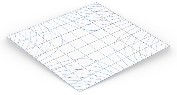
There is a close relationship between the development of cold-warped glass and the technology to enhance glass stiffness by prestress. Cold-warped glass is a common term in the architectural glazing industry describing flat glass that is elastically twisted out of plane to intentionally generate a non-planar surface. Twisting a plate transforms it into a hyperbolic paraboloid shape (Timoshenko and Woinowsky-Krieger 1987), as seen in Figure 1. It is also known that buckling of the shape arises as twisting continues (Eekhout et al 2004; Galuppi et al 2014).
In the search to identify specific conditions for the onset of buckling caused by cold-warping of glass, a loss in stiffness out of the plane was identified, and this stiffness loss becomes increasingly significant with increasing magnitudes of warpage (Bensend 2018). It is caused by membrane stress patterns that develop within the cold-warped glass panel, especially membrane compressions in the center region of the panel. These membrane stresses modify the deflection response where plates exhibit two-way, thin-plate behavior where transverse loads are resisted by both flexural and membrane effects.
Given that cold-warping flat glass into a hyperbolic paraboloid results in loss of stiffness, one valid question is whether glass initially formed to a hyperbolic paraboloid in its unstressed state and subsequently flattened would become planar and exhibit a corresponding increased stiffness and inverted stress state from the cold-warped version. This was confirmed first numerically, which culminated in patented claims (Bensend 2021) and was subsequently confirmed with testing on samples of chemically tempered 5mm glass, (Bensend and Zaccaria 2023).
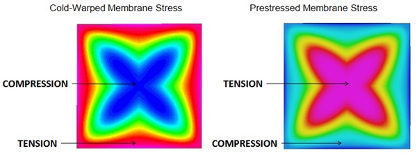
In this approach, membrane tensions result in the center region of the panel, and these tensions stiffen the membrane component of the large-deflection response. The response is similar to tensioning a slack cable – the capacity does not increase, but, the initial stiffness does. Unlike the cable analogy, membrane stresses are resolved internally to the prestressed plate, whereas a tensioned cable requires external support to directly resist the tensions. A comparison of membrane stress patterns is shown in Figure 2; similar, albeit inverted, membrane stress patterns in cold-warped and prestressed glass are evident.
The Appeal of Thin Chemically Tempered Glass
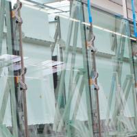
Architectural glass is produced by the float process which delivers a flat product with common thickness ranges between 4 and 25 mm. Within this range, the glass is stiff and difficult to bend, with excessive deformation resulting in brittle failure. When design calls for bent surfaces, hot and cold bending are two possibilities involving nearly stress-free or permanent stresses, respectively. The advent of smartphones has been pulling for the development of thin glass used for screens, calling for top-notch performances in terms of strength, optical quality, and flexibility. The flexibility related to its small thickness gives the freedom of no longer constraining the glass as a flat element, but nearly as a new material if compared to its thicker product. A few examples of ideas (Lambert & O'Callaghan, 2013) and prototyping (Louter et al., 2018), (Pennetier, Ronfini, & Stoddard, 2019) have been shared with the scientific community, but surely there are manufacturing complexities related to them, so the search for the best product using thin glass is still open. Flexibility alone though is not enough, and at times could be a limiting factor: if considering a flat insulated glazing made of thin glass, for example, the excessive deformation is by far the limiting factor.
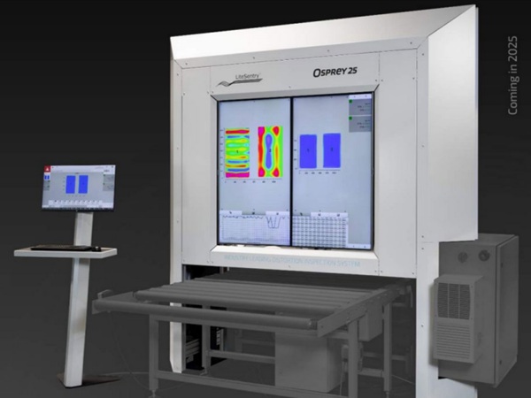
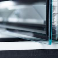
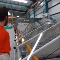
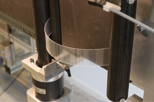
Thin glass requires strengthening, and this cannot be done by thermal tempering which has a current limitation set to 2 mm. That is why the go-to method for strengthening thin glass is chemical strengthening. The effectiveness of chemical strengthening is strongly related to the chemical composition of the glass, with aluminosilicate composition (ASG) being able to accommodate deeper case depth and higher surface residual compression if compared to soda-lime-silica glass (SLSG). In 2016 AGC started to produce Falcon Glass (AGC 2020), which has a composition between SLSG and ASG, allowing it to be produced by the float process despite its thickness ranging 0.5 mm to 2.1 only. Falcon Glass has good residual stress build-up when subjected to chemical strengthening, exhibiting fitness for applications calling for high strength whilst allowing large deformations. With the recent developments in testing thin glass (Maniatis, Nehring, & Siebert, 2014), (Neugebauer, 2016) and the construction and validation of a clamp bender (Zaccaria, et al., 2022) it is now possible to explore the thin glass world with a higher degree of confidence and push the boundaries that this ubiquitous branch of the glass world can offer (Figure 3).
3. Testing and Analysis
3.1. Objective and Test Plan
The aim of this project is to study the adaptation of the stiffening technology to thin, chemically tempered Falcon glass. To capture a range of possible conditions, two variables are considered. These two variables are the thickness and degree of initial warp.
First, a constant 1.1mm glass thickness is studied with varying degrees of prestress, by means of varying initial warp geometry. Second, glass thickness varying between 0.5mm, 1.1mm, and 2.1mm is studied for a given initial warp geometry. A target specimen size of 300mm x 300mm was established and the available substrate thicknesses were given values from which the initial warp geometry was selected based on suitability shown in the preliminary analysis. The objective geometry for test specimens is provided in Table 1 below, with the goal of obtaining at least one valid result for each geometry objective.
Each specimen was to be loaded with a concentrated force at midspan, with the intent of plotting force versus displacement to highlight the relative changes in stiffness between the various prestressed specimens and the control samples. Although a uniform pressure test is also a valid approach to assess the stiffness response, the convenience and speed of setup dictated the decision to proceed with a point load rather than a uniform pressure load.
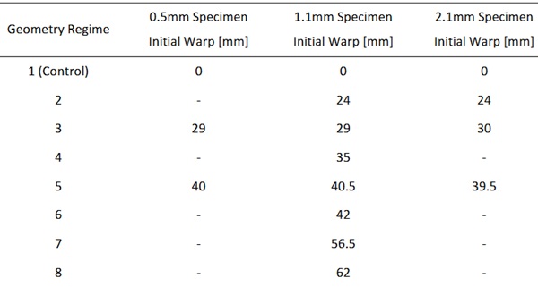
Table 1: Geometry Targets for 300mm x 300mm Specimens.
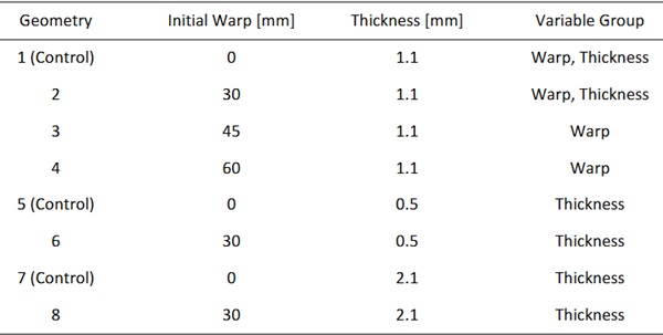
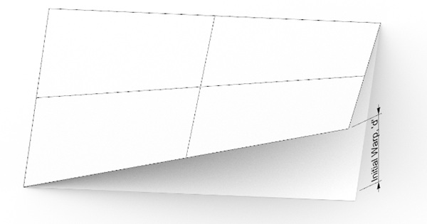
The target amount of initial warp for the specimen is defined as the distance from one corner of the glass normal to a plane that passes through the remaining three corners (Figure 4). This value was carefully selected based on preliminary analysis to ensure that glass would not be overstressed or become unstable by buckling before flattening could be achieved. The initial warp values also had to be large enough that the desirable effects from prestressing would be readily observable.
3.2. Preparing the Specimens
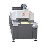
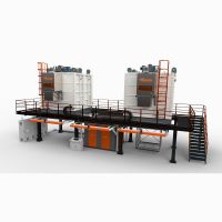
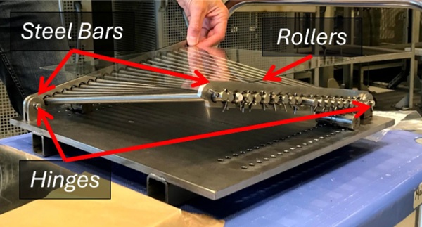
Hot bending glass is a process that is mastered by only a few specialised companies in the world and is surely complex. It is an accepted rule of thumb that single curvature bending can be done by slumping the panel into a mould, whilst double curvature bending typically requires a male-female type of mould. The target geometry of a hyperbolic paraboloid is a double curvature shape which is an exception to this rule – hot forming can exploit gravity to go from the flat to the curved shape if a purposely designed mould is used (Figure 5). The mould consists of two parallel steel bars connected to a plate by a hinge. The hinges are symmetrical along the diagonal of the plate. The plate has a set of holes conceived for fitting the pins protruding from a cylinder that can be conveniently placed to support the steel bars giving the desired angle, which will then determine the warp of the hyperbolic paraboloid. Steel rollers perpendicularly connect the two steel bars suggesting the final hyperbolic paraboloid. This clever mould allowed to perform the hot bending using laboratory equipment and limited investment.
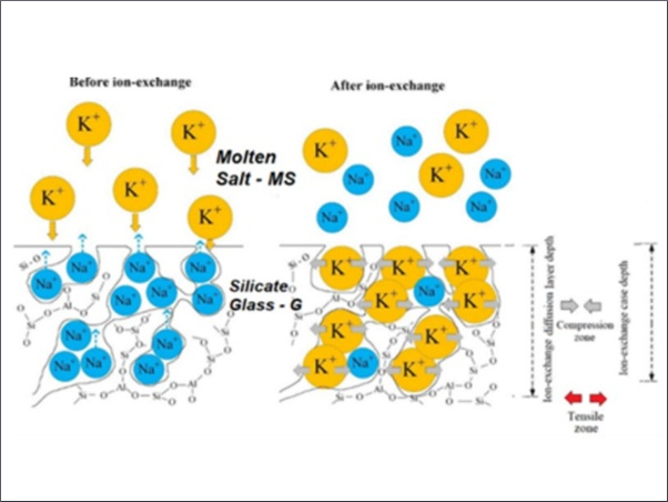
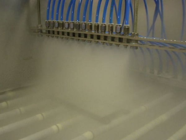
A furnace set to 675°C and an oven set to 250°C were used to perform bending. The flat piece of glass was first placed on the mould with the pins set for the desired warp. This setup was placed in the oven for pre-heating. As the glass reached the desired temperature, the mould was moved to the furnace by means of a manually operated forklift which allowed the lifting of the hot plate without risks for the operator. This operation was done as quickly as possible to avoid thermal shock breakage. The glass was held in the furnace just long enough to take the shape of the mould and then moved in the same way back to the furnace to allow slow cooling and prevent thermal shock breakage. Once cooled, the glass was in its hot-formed configuration. It should be noted that minor roller wave distortion was observed in the glass, with this being more pronounced on thinner glass: these could maybe be prevented by interposing a flat plate between the glass and the rollers. Following the hot-forming, the glass was sent for chemical strengthening, performed by immersing the glass in a molten bath of KNO3 for 8 hours. The actual warp of each glass was measured after all the processing was completed so as to best match the FE model.
3.3. Testing
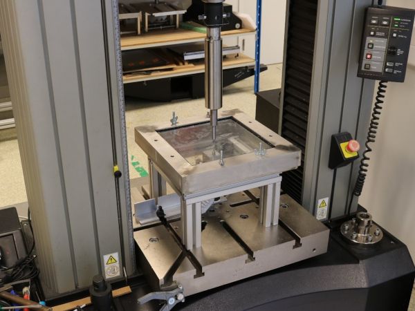
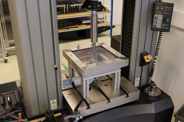
Each warped glass panel was tested by an Instron machine with a point on-frame setup by applying incremental loading steps up to failure (Figure 6). For each loading step the deformation was recorded so that load-displacement plots could be generated and compared with the FE results. The Instron was fitted with a pin in order to apply punctual loading in the center of the glass pane. In order to house a displacement gauge at the bottom of the glass, the glass was supported above the test bed by a metallic structure. On top of the structure, a frame was used for pressing and holding the warped glass back into flat position. To avoid direct contact between the glass and the metal, 2mm thick EPDM strips were placed between the glass and the frame and a silicone pad placed between the point-loading and the glass.
The flattening of the glass to the frame only required manual power and was done with precision by means of screws. A transparent film was placed on the side undergoing compression in order to keep the fragments together after failure. The speed of test was not constant as the interest of the test was the load-displacement and not the strength of glass. Nevertheless, for interrupting the test at the desired moment, a speed between 0.5 mm/min and 2 mm/min was suitable. The loading was incremented in steps of 50, 100 or 250 N.
Each flat glass panel was tested following the same procedure, that is also securing the glass in a frame to ensure the same boundaries conditions.
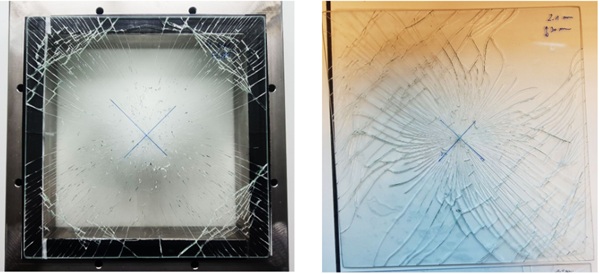
After failure, a picture of the broken sample was recorded to compare the different fracture pattern between the flat panels and the warped panels (Figure 7). It can be observed how the flat panels follow a radial propagation of failure, whilst the warped panel suggest the pre-stress level induced by the flattening frame with the fracture lines departing from the center, but then propagating with a curve.
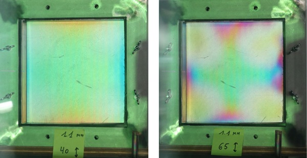
Prior to testing, the membrane stresses due to flattening the warped panels were inspected by means of a polarising filter (Figure 8). The strain pattern is apparent, and it appears to be more pronounced on the more highly stressed specimens as well as thicker specimens.
3.4. Finite Element Analysis and Results Comparison
After the specimens were hot-formed and chemically tempered, the initial warp dimensions were measured (Table 2). These differed from the targeted geometry due to the discrete nature of the custom mould. Additional warp geometries were provided for the 0.5mm and 2.1mm thickness regimes as well. Finite element models built to match the tested specimens.
Table 2: Measured Geometry for 300mm x 300mm Specimens.
Initially, the finite element models predicted deflection magnitudes greater than observed, regardless of whether the specimens were warped or conventional. It was determined that the boundary condition with overlap of the glass on the test frame likely responded more like a clamped condition than pin and roller condition. Models were adjusted and this assumption matched the observations much more closely.
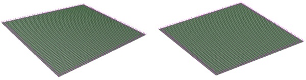
To model the clamped condition, the first and second nodes from the edges (6mm apart) at the perimeter for both prestressed and conventional cases are restrained normal to the surface. Regardless of the boundary condition, the effect of the added prestress is clearly visible, as is the increasing benefit for increasing amounts of prestressing warpage.
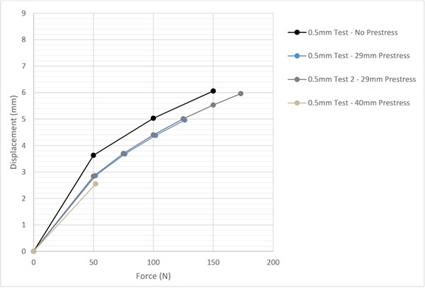
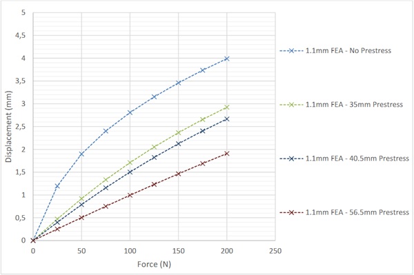
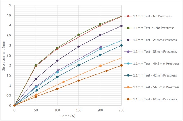
Figure 10 provides the finite element analysis results and Figure 11 the test results for 0.5mm glass. Figure 12 overlays both finite element results and test results for the 0.5mm glass. Similarly, Figures 13 through 15 provide results for the 1.1mm specimens and Figures 16 through 18 provide results for the 2.1mm specimens.

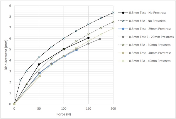
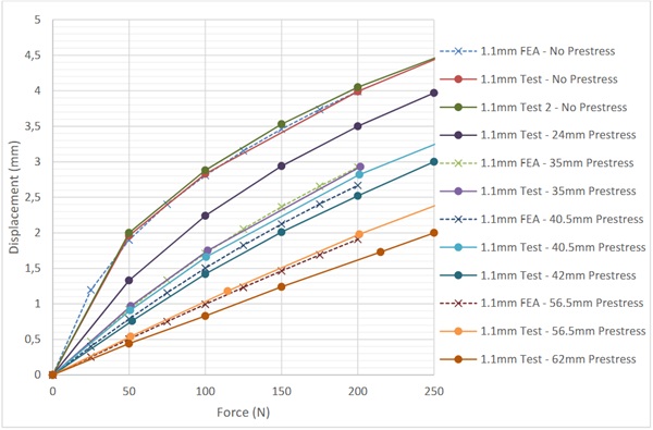
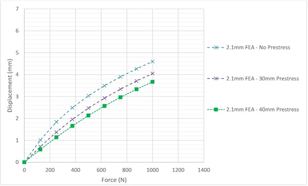
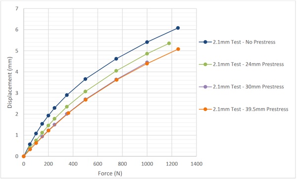
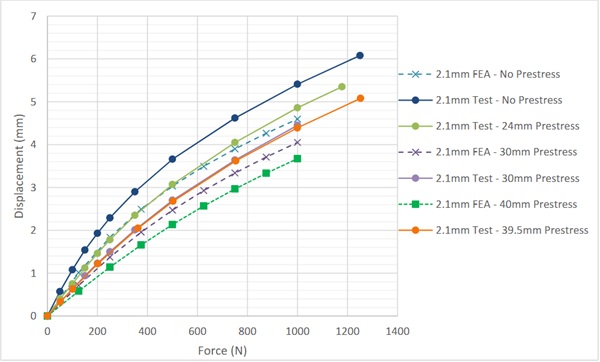
For discussion purposes, it appears from Figures 12, 15, and 18 that the finite element modelling overestimates the stiffness of the 2.1mm specimens and underestimates the stiffness of the 0.5mm specimens but closely tracks with the 1.1mm specimens. Perhaps this is related to the effects of the boundary condition not responding the same for various thicknesses, or perhaps this is even related to the stiffness of the EPDM, as the EPDM deformation would be included in the measurements taken. Regardless, it is clear on both finite element models and specimen testing that increasing prestress derived from flattening a warped shape results in increased stiffness.
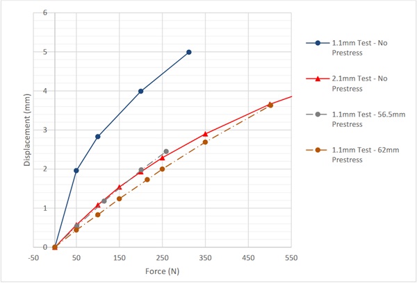
It is noteworthy to compare the prestressed 1.1mm glass to the conventional 1.1mm glass. Figure 19 shows that the conventional glass deflects 2mm at a load of just 50 N, while the prestressed glass resists approximately 5 times that load, 250N, before the 2mm threshold is crossed. Similarly, comparing deflections at the 250N load, the conventional glass deflects approximately 4.4mm, while the prestressed glass deflects approximately 2mm. In other words, it is twice as stiff for that load level.
A comparison of the test result data for 1.1mm prestressed and 2.1mm control specimen yield some remarkable results. The prestressed 1.1mm specimen can meet or exceed the stiffness of a conventional 2.1mm specimen, also shown in Figure 19. In other words, the same deflection performance can be achieved with just over half of the raw materials.
4. Conclusions
The ability to substantially enhance the stiffness of glass is clearly achievable using chemically tempered thin glass on gravity moulds for a thickness range of 0.5mm to 2.1mm. This phenomenon is also understood to be scalable to thicker glass in larger formats. Much work remains to discern the limits of the technology and identify conditions where this application might prove most beneficial. Regardless, in a world that is concerned with increasing performance and reduced material use, it is conceivable that this technology provides a pathway toward both objectives.
References
AGC. (2020). Falcon glass data sheet. Retrieved from https://www.agc-yourglass.com/sites/default/files/agc_docs/Falcon_0420_EN.pdf, Accessed 15 March 2024.
Bensend, A. (2018). The Effects of Cold Warping on Glass Stiffness. Challenging Glass 6 - Conference on Architectural and Structural Applications of Glass. Belis, Bos, Louter, Veer, and Nijsse (eds.), May 2018: pp. 85-96. Delft. https://doi.org/10.7480/cgc.6.2119
Bensend, A. (2021). Pre-stressed Plate or Shell Structures. U.S. Patent 10,913,243.
Bensend, A., & Zaccaria, M. (2023). Pre-stressing Glass by Elastic Deformation: A New Twist on Reducing Deflection. Glass Performance Days. Tampere: pp. 28-31.
Eekhout, M., Staaks, D., and Van Herwijnen, F. (2004). Cold Bent Glass Sheets in Façade Structures. Structural Engineering International (SEI), 14(2): pp. 98-101. https://doi.org/10.2749/101686604777964134
Galuppi, L., Massimiani, S., Royer-Carfagni, G. (2014). ‘Buckling Phenomena in Double Curved Cold-bent Glass’. International Journal of Non-Linear Mechanics. 64: pp. 70-84. https://doi.org/10.1016/j.ijnonlinmec.2014.03.015
Hakim G., Abramovich H. (2022). ‘Large Deflections of Thin-Walled Plates under Transverse Loading—Investigation of the Generated In-Plane Stresses’. Materials, 15(4): 1577. https://doi.org/10.3390/ma15041577
Lambert, H., & O'Callaghan, J. (2013). Ultra-thin high strength glass research and potential applications. Glass Performance Days. Tampere: pp. 95-99.
Louter, C., Akilo, M., Miri, B., Neeskens, T., Ribeiro Silveira, R., Topcu, Ö., van der Weijde, I., Zha, C., Bilow, M., Turrin, M., Klein, T., & O'Callaghan, J. (2018). Adaptive and composite thin glass concepts for architectural applications. Heron, 63(1/2), 199-218. Article 9. http://heronjournal.nl/63-12/9.html
Maniatis, I., Nehring, G., & Siebert, G. (2014). Studies on determining the bending strength of thin glass. Struct. Build., pp. 393-402. https://doi.org/10.1680/jstbu.14.00003
Neugebauer, J. (2016). Determining of bending tensile strength of thin glass. Challenging Glass 5 - Conference on Architectural and Structural Applications of Glass. Belis, Bos, Louter(eds.), June 2016:pp. 419-428. Ghent. https://doi.org/10.7480/cgc.5.2267
Pennetier, S., Ronfini, A., & Stoddard, J. (2019). Advances in prototyping with ultra-thin glass. Glass Performance Days. Tampere: pp. 302-308.
Timoshenko, S. & Woinowsky-Krieger, S. (1987). Theory of Plates and Shells, 2nd ed. New York, NY, McGraw-Hill: pp. 43-44, 47-48, 396.
Zaccaria, M., Peters, T., Ebert, J., Lucca, N., Schneider, J., & Louter, C. (2022). The clamp bender: a new testing equipment for thin glass. Glass structures and Engineering. 7(2) pp. 173-186. https://doi.org/10.1007/s40940-022-00188-8