The Paper was first presented at GPD 2017 by Dr. Mikko Rantala, Glaston Finland Oy.
The PVB-film should be heated up to a temperature of about 60°C before it enters into a nip roll at the end of the oven. Usually, heating is arranged with conventional heating resistors located in a heating chamber. In some ovens, the heating is based on forced convection. In these, hot air jets are blown toward the glass-film sandwich.
Glass and PVB have low thermal conductivity. So, it takes time to transfer heat to the inner film in a multi-film layer sandwich. The spokespersons of the radiation ovens catch of the problem and express that radiation heating helps, because the radiation penetrating through the glass is absorbed by the film.
The statement that clear and low-e coated glass-film sandwiches can be processed with the same speed is given as an advantage of convection heating. Thus, there exist various kinds of argument as to how heating should be arranged. The paper aims to end the speculation. It shows theoretical results for how various glass-film sandwiches heat up in radiation and convection ovens.
1. Introduction
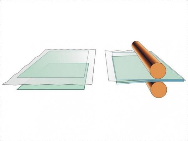
In a glass laminating process, sheets of glass are stuck together with a polyvinyl butyral (PVB) film between them. A typical PVB-film thickness is 0.76 mm. At first, PVB is placed between glasses in a laminating room. Then, the whole sandwich containing glasses and films is heated up in a de-airing conveyor in which heating is arranged with thermal radiation and/or forced convection. In a flat glass de-airing conveyor, i.e. a laminating oven, glass-film sandwiches are located on rotating rollers and conveyed through a heating chamber in a continuous flow.
There is a nip roll before and after the oven. Even lines without the first nip roll exist. The air from glass-film interfaces is pressed out when a sandwich goes through the nip. The major function of the de-airing, in addition to sticking and air removal, is edge sealing, which prevents air re-penetration into a sandwich. Next, the bond between glass and film is stabilised in an autoclave, which is a hot pressure chamber.
Autoclaving presses and breaks remaining air bubbles into smaller sizes and then dissolves them into the film. In a flat glass laminating oven, glass-film sandwiches are heated up to a temperature of about 60-70°C measured from the surface, when a sandwich comes out of the oven (nip roll) to the unloading table. Surface temperatures above 90°C are avoided.
Usually heating is arranged with conventional heating resistors located near the ceiling and roof in a heating chamber. Also, so-called quartz tube heaters, emitting near- and mid-infrared radiation, are used in some ovens. In the ovens mentioned above, heating is based on the radiation heat transfer. In some ovens, the heating is based on forced convection. In these, fans circulate hot air inside the oven, and hot air jets are blown toward the glass-film sandwich.
Both materials, i.e. glass and PVB, have low thermal conductivity. So, it takes time to transfer heat into the inner film in a multi-film layer laminate, when at the same time the overheating of the outer film must be avoided. That limits the heating speed of multi-film layer laminates. As to heat transfer, an interesting detail is that glass and PVB are semi-transparent for thermal radiation, and both materials have their own spectral absorption properties. There are various kinds of beliefs as to how heating in lamination oven should arranged.
The spokespersons of the radiation ovens claim that the most efficient means for heating the glass-film sandwich is to use near- or mid-infrared radiation, which penetrates through the glass but is absorbed into the film. The statement that clear and low-e coated glass-film sandwiches can be processed at the same speed is given as an advantage of convection heating. The paper aims to end the speculations. It shows the theoretical results how various glass-film sandwiches heat up in radiation and convection ovens.
2. Emission from a black surface
All objects emit radiation on the basis of their temperature, which is called thermal radiation. An ideal black surface has complete emission and absorption of incident radiation at all wavelengths, and from all directions. The spectral distribution of the hemispherical emissive power of a blackbody is given as a function of a wavelength and absolute temperature (K = °C+273) by
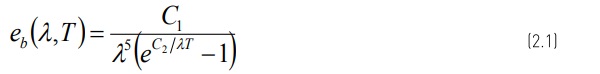
This is known as Planck’s spectral distribution of blackbody emissive power. In Eq. (2.1) C1 = 2TThc02 = 3.7419×10⁻¹⁶ Wm2 and C2 = hc0 /k = 14,388 µmK, where k is Boltzmann’s constant and h is Planck’s constant. Eq. (2.1) is solved for three surface temperatures in Figure 2.1.
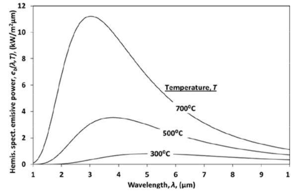
As seen in Figure 2.1, the spectral distribution of the emissive power shifts towards shorter wavelengths when the temperature of a blackbody increases. The wavelength λpeak at the peak of the spectral distribution can be calculated from Wien’s displacement law
where C3 = 2897.756 µm. In Figure 2.1 the area between curves and the wavelength-axis is equivalent to the total emission of a blackbody, and is obtained from the Stefan-Boltzmann equation
in which σ= 5.6703×10⁻⁸ W/(m2K4).
3. Absorption of thermal radiation in a glass-film sandwich
In Figure 3.1, the behaviour of incident radiation hitting a glass-film sandwich is shown schematically. At air-glass interface, a proportion of the radiation is reflected. The reflectivity depends on the hitting angle and the wavelength [1]. Because of the low reflectivity (typical direction-averaged value is 0.09) of a clear glass surface, the main proportion of radiation goes through the interface. The radiation to which glass is opaque is absorbed to a glass surface.
The radiation to which glass is transparent penetrates deeper into glass, and the proportion of it absorbed into the glass. The rest of the radiation meets the glass-film interface, where a second reflection occurs. Without air at the interface, i.e. after the de-airing, the reflectivity of the interface is minimal, because glass and PVB have almost the same refractive indices. In the spots where air is between glass and film, the reflection occurs from glass-air and air-film interfaces. It is apparent that the reflectivity of the interface decreases during heating in a laminating oven, because the contact between glass and film is getting better. Now, value Pλint = 0.10 is used in the modelling.
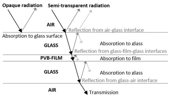
Due to absorption, the intensity of the radiation attenuates when it propagates in glass. Bouguer’s law is the mathematical relation describing the reduction in intensity of radiation as it travels along a path of finite length within a medium. The intensity of radiation after a path distance x in a medium is

where i0 is the intensity at the surface and κ is the absorption coefficient, which is the property of a medium that describes the amount of absorption of thermal radiation per unit path length within the medium.
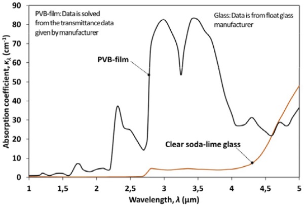
Figure 3.2 shows the spectral absorption coefficient of clear soda-lime glass and PVB-film. Soda-lime glass has two cut-off wavelengths, at which its absorption coefficient undergoes a major change. Practically speaking, glass is opaque for thermal radiation when the wavelength is over 4.5 µm, whereas for wavelengths under 2.75 µm, glass is very transparent. At wavelengths between 2.75 and 4.5 µm, the absorption coefficient is about 4 cm-1, which is still a relatively high value.
At wavelengths between 1 and 2.75 µm, the absorption coefficient is about 0.3 cm-1. The spectral transmissivity through 3 mm (=typical minimum glass thickness in a flat glass laminating oven) thick glass is about 28%, when κλ = 4 cm-1, and 84%, when κλ = 0.3 cm-1 (hitting angle = 0°). The absorption coefficients at wavelengths below 4.5 µm are higher when the concentration of iron oxide in glass increases. Such a glass has a greener colour, and its light transmission is also lower than it is for clear glass.
As shown in Figure 3.2 PVB-film has a much higher absorption coefficient at wavelengths between 1 and 4.5 µm than glass. The curves in the figure easily gives the impression that the wavelength band 2.75-4.5 µm is the optimal in order to get radiation through glass to the PVB-interlayer.
Well, this is true if the glass is very thin, but as given above even 3 mm glass absorbs the major proportion of such a radiation before it reaches the PVB. So, the wavelength band 1.7-2.75 µm can be classified as the best for the purpose above. The absorption coefficients of the PVB-film above 4.5 µm have not any effect on the heating speed of glass-film sandwich, because such radiation is absorbed by the surface glass.
With the directional spectral reflectivity, spectral absorption coefficient and Bouguer’s law Eq. (3.1) it is possible to formulate the directional spectral absorptance of a layer in glass-film sandwich. For total absorptances, the integration over the polar angle 0–90° is needed. Now, the Averaged Net Radiation method developed in [1] for clear and coated glass is applied in solving spectral total absorptances of layers in a glass-film sandwich.
In this method, instead of the complicated integration, the special direction-averaged values are used for spectral reflectivity and penetration angle in a sandwich. The integration over wavelengths is covered by using wavelength bands inside which the radiative properties are quite wavelength-independent, which is a common method in the literature of the field.
The radiative properties of some low-e coatings are given with details in [1], from which the following main points are chosen. A low-e coating changes glass surface reflectivity selectively. For visible light (0.4 < λ < 0.7 µm), reflectivity remains almost constant, but at slightly longer wavelengths, reflectivity increases sharply to 0.8 - 0.97 depending on the coating. The coating itself also absorbs radiation, and its absorptivityi s slightly dependent on wavelength.
4. Description of the heat transfer problem
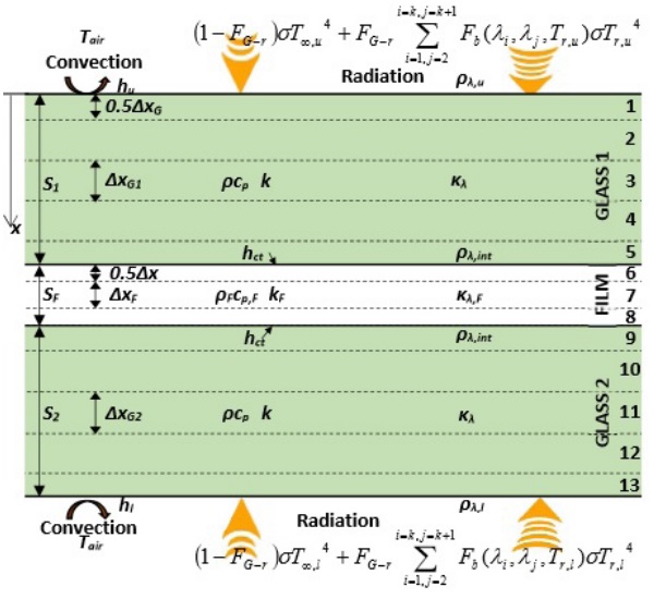
Figure 4.1 shows the schematic of a glassfilm sandwich inside a laminating oven. The sandwich is exposed to radiation, and convection heat transfer between hot air and glass affects both surfaces. In Figure 4.1 the radiative heat flux is divided to two proportions.
The proportion FG-rΣFb (λi .λj ,T)σTr 4 = qr2 stands for the radiative heat flux from the radiant heaters and the proportion (1-FG-R)σT∞ 4 stands for the radiative heat flux from other inside surfaces of the oven toward to the sandwich.
Above FG-r is the view factor from the sandwich to heaters, and Fb (λi ,λj ,Tr ) is the fraction of radiative energy of a blackbody between the wavelengths λi and λj at temperature Tr . The division of radiative heat flux above is needed, because in some ovens the temperature of radiant heaters is clearly higher than the temperature of other surfaces. Then, the proportions consist of clearly different kinds of thermal radiation. Heaters emit shorter wavelength radiation, which can partly penetrate deeper into the sandwich.
The radiation emitted by other surfaces affects only the outer surfaces of the sandwich alike convention. At 200°C, which is quite typical control temperature of a laminating oven, 91% of the radiative energy emitted is opaque for glass (λ < 4.5µm). In a laminating oven, the sandwich is always so cold that only its outer surfaces are emitting radiation, and the emission increases when the glass gets hotter. Thermal conduction transfers heat from hotter to colder layers inside the glass-film sandwich. The problem is to solve the development of the thickness-wise temperature profile in a glassfilm sandwich during heating in a laminating oven.
4.1 Solving method
In the explicit finite difference method, the glass is divided into layers (volume elements), the calculation proceeds by time-step ∆t at once and the results after the last time-step are used as initial data for the next time-step. In Figure 4.1, both glass thicknesses (S1 , S2 ) are divided into five layers, and the film thickness SF to three layers. The thickness of each surface layer is one half the thickness of the inner layer. Thus, the thickness step ∆x in glass 1 is S1 /4 and in film SF/2.
Glass density ρ = 2530 kg/m3 and film density ρF = 1060 kg/m3 . Now, specific heat cp = 920 J/(kgK) stands for the glass and cp,F = 2100 J/(kgK) for the film. In the inner layers of glasses and film heat transfer occurs by conduction between adjoining layers and absorption of radiation emitted by heating resistors. Thermal conductivity k = 1 W/(mK) stands for the glass and kF = 0.25 W/(mK) for the film. For instance, the energy balance for the inner layer 4 in Figure 4.1 can be written as
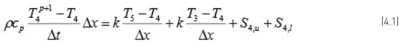
where superscript p+1 indicates the future after time-step ∆t. In the energy balance, the temperature T4 covers the whole layer, but its accurate coordinate is in the middle of layer 4 at the thickness of 3∆x from the glass upper surface. Net radiation is taken into account with source terms S4 written separately to upper and lower side radiation. The source terms for each layer in a glass-film sandwich in Figure 4.1 can be formulated in a corresponding way as in [1] for the clear and low-e coated glass.
In addition to conduction and radiation, convection also occurs in glass surface layers. Convective heat flux qc can easily be specified using a convection heat transfer coefficient and temperature difference between air and glass surface qc =hu (Ta -T1 ). The evaluation of the correct value of the convection mean heat transfer coefficient is often difficult. Now, the convection mean heat transfer coefficient hu = hl = 50 W/(m2 K) is used in the modelling of a convection oven, the value of which is based on measurements from Glaston ProL convection oven.
The efficiency of conduction from the glass to PVB-interlayer depends on the purity of the contact between them. In this method, the heat transfer through the interface between the upper glass and PVB-interlayer, for instance, is calculated from the equation qct=hct(T5 -T6 ), where hct = 1000 W/(m2 K) is the contact heat transfer coefficient. The value above is based on the measurements, which indicated that the value can be even higher. The exact value is not important for the accuracy of the modelling results in the next chapter, because the value is great anyhow.
5. Results
The ovens modelled are convection oven (oven 1), typical radiation oven (oven 2) and special radiation ovens with two kinds of radiant heaters (ovens 3 and 4). In oven 1, the convection heat transfer coefficient and heating air set temperatures are as in the Glaston ProL oven. The typical radiation oven is equipped with conventional heating resistors, keeping the oven temperature control thermocouple at a set value. In the special radiation ovens, extra heating resistors are forced on when the glass-film sandwich is in their heating zone.
It assumed that, when they are turned on, resistors instantly reach the heater temperature used in the modelling. This is certainly true in oven 4, because in practice a heater temperature of 2,000°C enables resistors to be thin filaments inside a quartz tubes alike in a light bulb. The operation of such a heating resistor is treated in detail in [2]. Now, the heaters are just black surfaces at given temperatures in the modelling. Table 5.1 defines the circumstances in the ovens modelled.
The thin glass-film sandwich modelled consisted of two sheets of 3 mm glass and a PVB-film between them (Thin = 3 + 0.76 + 3 mm). The thick sandwich modelled consisted of four sheets of 4 mm glass and film layers between them (Thick = 4 + 0.76 + 4 + 0.76 + 4 + 0.76 + 4 mm). Three different cases for both sandwiches were modelled. In the first glasses were clear, in the second the top side and in the third the bottom side of the uppermost glass was low-e coated. In the modelling of the third case above, the radiative properties of the low-e coating against the PVB-film were assumed to be the same as in air interface.
Ovens 1 and 2 represent the ovens on the market, so the comparison of their results gives practical information for those who are planning to invest in a lamination line, for instance. Ovens 3 and 4 are more theoretical. In these, the extra heater power was set as the same as the convection heating power at the beginning of the heating in oven 1, when the thin sandwich was modelled. The temperature of inside surfaces of the oven (excluding extra heaters) was also kept the same in ovens 1, 3 and 4.
In the case of the thick sandwich with clear glasses (first case) the initial convection heating power in oven 1, and the extra heating power in ovens 3 and 4, was as high as possible to avoid uppermost glass top surface temperatures above 85°C. The heating powers was kept the same, when the sandwiches with a low-e coated glass (second and third case) were modelled. The maximum was limited to 8 kW/m2 used with the thin sandwich.
Such a procedure aimed to keep the comparison between convection and radiation heating more practical and comparable. In oven 1, the set air temperature was lowered from 180°C to 140°C to keep the temperature of the top surface of the thick sandwich below the limit above. The heating was assumed to be ready, i.e. the sandwich proceeds to the nip roll after the oven, when all PVB-film layers were above 60°C.
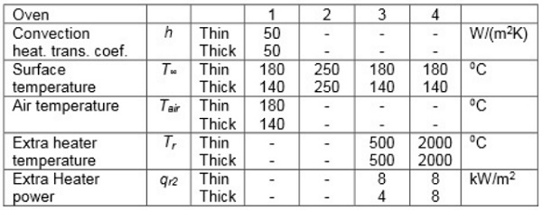
Figures 5.1-5.3 show the development of thickness-wise temperature profiles in the thin glass-film sandwich. Temperature profiles are given for heating times of 10, 20, 31 and 41 s, and the latest profile in each figure is taken when the heating is ready. Thus, convection oven 1 heats up the thin sandwich with clear glasses in 44 s, typical radiation oven 2 in 100 s, and so on.
Special radiation oven 4 is 25% slower than special radiation oven 3, because it emits shorter wavelength radiation penetrating more through the thin sandwich. In all cases, the uppermost glass surface temperature is clearly below the limit above. The temperature profiles in oven 4 are clearly smoother because of short wavelength radiation absorbed by the film and glass interior. In it, the film clearly absorbs the radiation, because its temperature is higher than the glass inner surface temperature.
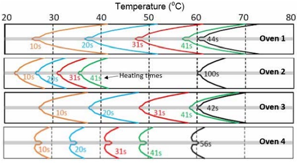
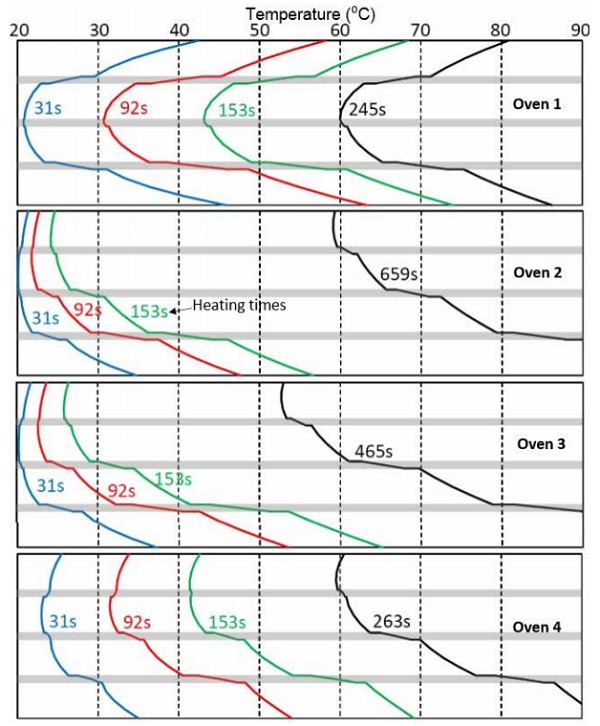
As seen from Figure 5.2, the low-e coating on the top surface of the upper glass has a very high impact on the heating speed of the sandwich in radiation ovens 2–4. Additionally, the temperature profile becomes very asymmetrical. For convection oven 1, the heating speed in Figure 5.2 is close to the heating speed without low-e coating in Figure 5.1.
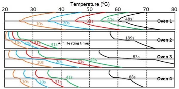
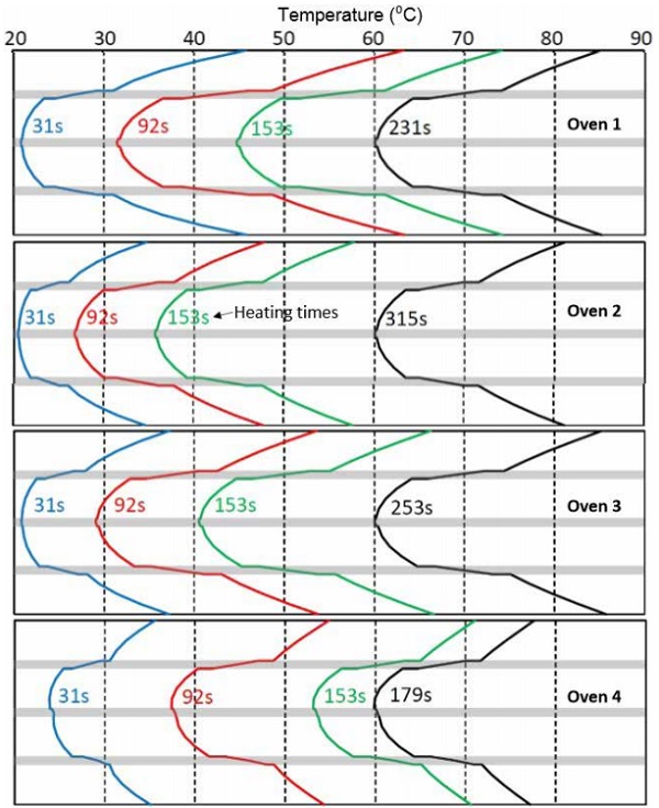
If the low-e coating is in the bottom surface of the upper glass, as in Figure 5.3, its effect on heating speed is insignificant.
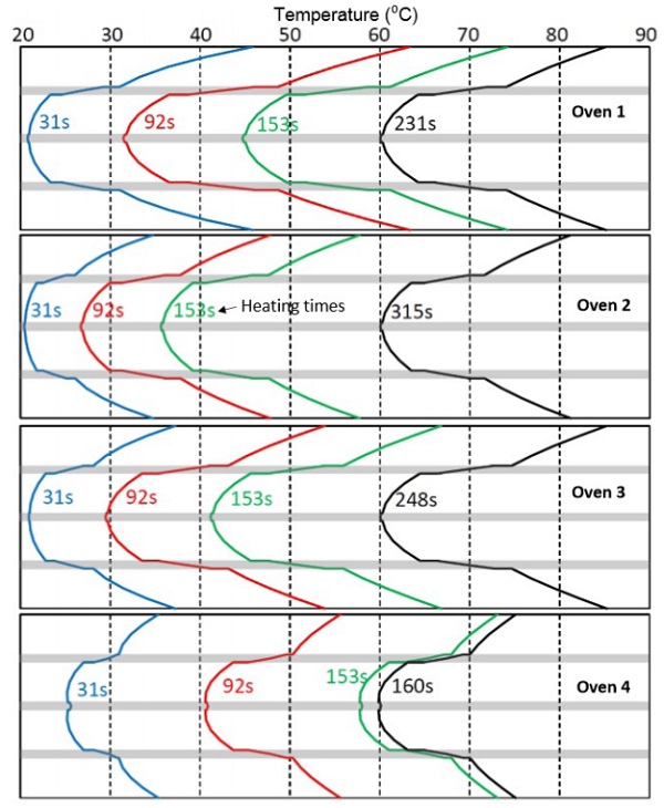
Figures 5.4-5.6 show the development of thickness-wise temperature profiles in the thick glass-film sandwich. Temperature profiles are given for heating times 31, 92 and 153 s, and the latest profile in each figure is taken when the heating is ready. Thus, convection oven 1 heats up the thin sandwich with clear glasses in 231 s, typical radiation oven 2 in 315 s, and so on.
The special radiation oven 4 is now the fastest, because only in it could the extra heating power be kept as the same as with the thin sandwich. Despite of that the surface temperatures of the sandwich are clearly lower as the ones in ovens 1 and 3. So, the extra heating power in oven 4 could still be raised. The thick sandwich is so thick that the short wavelength radiation emitted by the radiant heaters at 2,000°C is absorbed effectively into it.
According to Figure 5.5, oven 4 is almost as fast as the convection oven 1 even for sandwich in which top surface of the uppermost glass is low-e coated. In practice, the speed difference is higher, because the bottom surface temperature of the sandwich in oven 4 is clearly higher than the limit above. So, to keep the comparison balanced, the extra heating power in oven 4 should be cut by shutting down some heaters. If the low-e coating is on the bottom surface of the upper glass, as in Figure 5.6, its effect on the heating speed in ovens 1–3 is minimal. In oven 4, the heating time increases +12%, which in practice is still quite insignificant.
The results above match for the glass-film sandwich area excluding the area near the edges, where heat transfer is two or three (corners) dimensional. The edge area tends to heat up more quickly than the mid areas of the sandwich, because the surfaces in the oven radiating heat above and below the midareas of the sandwich are more loaded by the cold glass-film sandwich, and cool more than other surfaces during heating.
The edges of the sandwich are also an extra heat transfer surface, whose effect increases with sandwich thickness. It is unavoidable that the edge area heats up more quickly, but it is also desirable to ensure that edges are sealed, when the nip roll after the oven presses the sandwich. On the other hand, in de-airing it is important that the edges are not sealed before the nip roll, so that air can be pressed out from the sandwich.
So, the temperature difference between the edge area and mid area of the sandwich is desirable only to certain limit. Now, only the following two sentences can be written considering the level of the edge heating problem above in radiation and convection ovens. The intensity (W/m2 ) of radiation heat transfer on the edge surface (thickness-wise surface) is at least equal to the intensity on the main surfaces. The forced convection heat transfer coefficient is clearly smaller at the edges than at the main surfaces to which air jets are focused.
6. Conclusions
Forced convection heating in a laminating oven is the optimal solution particularly for thin glass-film sandwiches in which the convection heat is quickly conducted from surfaces through a glass to a PVB-film. Convection heating enables high line speed and/or short oven length, and is easy to control. As to heat transfer, a typical radiation oven equipped with relatively low temperature radiant heaters does not have any benefits compared with the convection oven modelled.
The wavelength band 1.7-2.75 µm is the optimal to get radiation through the glass to the PVB-film, and in such a way speed up the heating in a laminating oven and keep the thickness-wise temperature gradient in a sandwich smooth. Such a radiation helps particularly when the sandwich has more than two film layers.
This benefit of radiation heating as opposed to forced convection heating can be utilized only with the heaters in which the resistor is a thin and hot filament in a protective gas inside a quartz glass tube. The filament temperature in such a heater should rather be about 2,000°C. A notable part of the radiation at the wavelength band above gets through a thin glass-film sandwich, which reduces the heating speed.
The glass-film sandwiches with clear and low-e coated surfaces can be processed with the same heating recipe when the rate of the forced convection is high enough, as in the convection oven modelled. In all kinds of radiation ovens, the line speeds must be slowed down dramatically, when an outer surface of the sandwich is low-e coated. A low-e coating on the inside interface of the sandwich does not affect the line speeds.
References
[1] Rantala, M., Heat Transfer Phenomena in Float Glass Heat Treatment Processes. Tampere University of Technology. Publication, Vuosikerta. 1355, Tampere University of Technology, 2015.
[2] Petterson, M. and Stenström, S., Modelling of an electric IR heater at transient and steady state conditions - Part 1: model and validation, International Journal of Heat and Mass Transfer, p. 1209–1222, 2000.