This paper was first presented at GPD 2019 by Jim Gulnick from McGrory Glass, Inc.
Whether multiple panels are desired to be mounted on a wall many stories high, or overhead in a suspended solution, structural soundness and testing is required. This presentation discusses the seismic field testing of a glass mounting system to become AMAA 501.6 compliant (seismically rated). Engineering analyses of a wall mounting system will be covered, along with details of seismic testing and the results obtained.
Pictures and graphs will show materials tested, methodology, and performance measures for the decorative laminated glass that was studied in this research. Structural analysis was carried out by a third-party engineering firm. The seismic testing was conducted by a third-party laboratory and confirmed the theoretical performance of the system through actual seismic shaking simulation in accordance with AMAA 501.6 (compliance).
Impact of Seismic Events
Much of the highly populated regions of the world and over 4.3 million businesses in the United States are at risk to seismic events with indirect business losses estimated to be greater than $2 billion per year [1]. Earthquakes signify one of the greatest damaging natural hazards worldwide and although relatively scarce in reoccurrence in any one specific place, are a high risk, but low likelihood, incident creating major architectural and human impact [9].
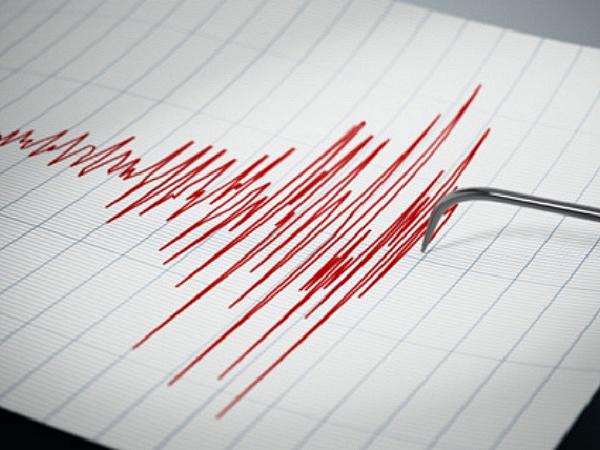
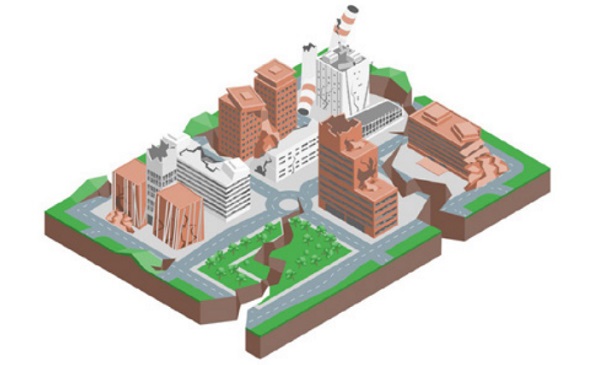
The rate of change of speed is measured in relationship to gravity with a freefalling object accelerating at 9.8 m/sec² or a gravitational force of 1.00 g [1]. Small acceleration forces or shaking back and forth due to earthquakes are felt by people and as little as 0.02 g can make people lose their balance [1]. Stronger forces can cause major destruction as building components may not be able to withstand the rapid and sudden movements back and forth [Figure 1]. Earthquakes can reach acceleration forces of 0.5 g and beyond as they shake back and forth.
Non-Structural Components and Contents
Non-structural systems include elements that are not part of a building’s primary structure but are necessary for the building to function such as mechanical, electrical, plumbing and other engineered systems and services [2]. Building contents, such as furniture, fixtures and fittings, are not non-structural systems [2]. Both non-structural systems and building contents can be damaged and create hazards as results of earthquake shaking and pose threat to life and safety.
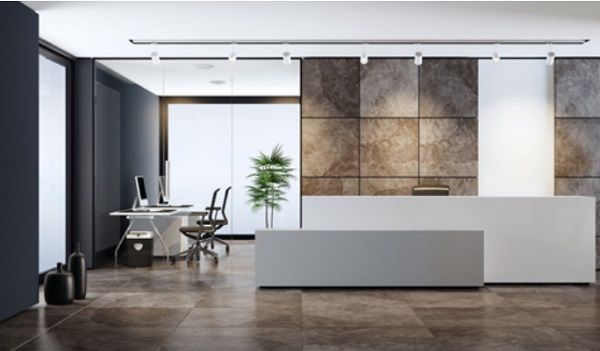
Non-structural elements can also be classified as architectural components, mechanical and electrical equipment, and building contents and inventory [8]. Glass architectural components may include but not be limited to decorative partitions, wall cladding [Figure 2], and laminated ceiling systems [8]. The costs due to damage of non-structural elements may be as much as 65-85% of the complete construction cost for commercial buildings [8].
Glass Façades and Cladding
The results and effects of seismic action on glass façades and wall cladding systems [Figure 3] are transmitted through the structure to which they are attached [5]. A seismic compliant large format glass mounting system must consider the movement and forces imposed on it by the building structure and remain intact without 1 square inch of material fallout during AAMA 501.6 testing [7].
In the event of an earthquake, the building itself is the most likely cause of injury or death [6]. It is the role of the building codes to stipulate the minimum requirements to effectively protect the health, safety, and wellbeing of building occupants [6]. Many of the injuries from seismic events also may be contributed by the impact from non-structural elements and therefor anchorage of heavy components such as wall cladding to prevent fallout and resist large forces is necessary [4].

Glass is attached to Moving Structures
Glass cladding system design and installation must be carefully developed in order to anticipate the interaction between the cladding and building structure during an earthquake [3]. The possibility of glass breakage and fall out or detachment of façade or cladding panels poses a significant risk to the well-being of occupants so the systems must be able to accommodate design drift of the structure [3]. With that in mind, architects and designers requested more robust and secure decorative glass mounting solutions that would enable beautiful and lasting aesthetics with safe and secure installation.
Architects Request Seismic Stability
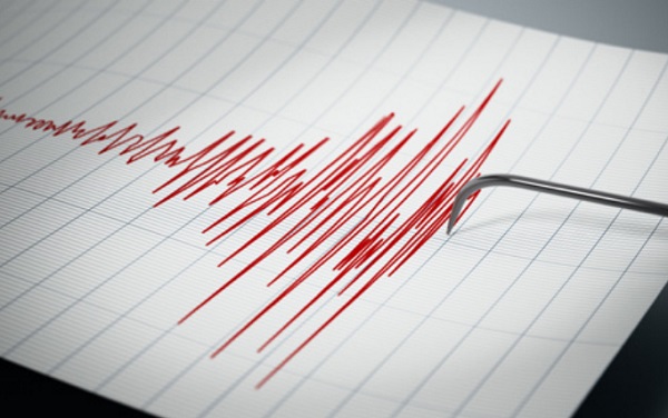
Architects on the West Coast have been concerned about seismic safety for many years while only in recent years have East Coast architects started to understand that earthquakes [Figure 4] - along with natural disaster causing weather such as tornados and hurricanes - can happen anywhere, causing buildings to move. While architects expect rigorous testing of exterior elements like façades, curtain walls, envelopes and windows, often the wall systems installed inside these buildings typically are not tested for stability during extreme weather events - or can even meet those requirements.
These types of interior glass-mounting systems weren’t even available. It wasn’t seismically prudent to mount glass on your wall. The results were unknowable, and safety couldn’t be guaranteed. Hospitals, schools, corporate offices, airports, luxury high rises, commercial and retail spaces, are just a few of the spaces frequented by people and susceptible to impact.
The Development of the Structural Mounting System
A high-profile building project in Philadelphia (think: 500-pound glass panels mounted on walls up to 13 stories high) required single source responsibility for both large, heavy, decorative glass and a secure mounting system. The building owner did not want to separate responsibility for glass and mounting system. Lower risk of installation issues can be realized by putting the responsibility for the mounting solution on the cladding supplier.
With 50,000 square feet of glass being installed 13 stories up the inside of a building, the engineering team and a local glazier became invaluable resources. McGrory collaborated with Eckersley O’Callaghan’s and Eureka Metal & Glass Services, Inc. What resulted was a new way to mount glass that provided installation and removal of any piece, at any time, and any place without disturbing any other [Figure 5].
Viscoelastic Interlayers
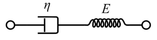
Glass is a commonly used but not extensively understood decorative element of which the behavior of the system in which it is being used is modeled to help predict strength and stability performance under various structural conditions [12]. It is well known that laminated glass interlayers exhibit both elastic and viscous behaviors when deformed [Figure 6].
Their mechanical properties are also driven by load, rate or period of movement, and temperature [13]. For instance, interlayers commonly become softer when heated, and stiffer when cooled. When stress is applied to the interlayer, it resists as if an elastic spring in a recoverable manner while simultaneously viscously elongating over time in what becomes a permanent stretch. Progress in analysis tools and advances in understanding of interlayers have significantly increased behavioral comprehension and therefor lead to more insightful predictive models for laminated glass [14].
Finite Element Analysis
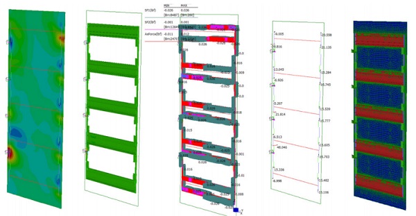
The development of the system took place over a quite extensive period of iterations between the McGrory fabrication and installation team and Eckersley O’Callaghan, with very detailed Finite Element Analysis [Figure 7] to verify and optimize the overall system and component performance. Through this process of continual refinement in the design, the target end result was to be a simple system that conceals the advanced engineering involved. It needed to solve the commonplace conundrum of glass cladding while providing no visible means of support. A few of the important details of the engineering analysis by Eckersley O’Callaghan will be shared along with narrative.
Decorative laminated glass, framing, adhesive, and framing screws were all included with the finite element analysis by Eckersley O’Callaghan.
The System
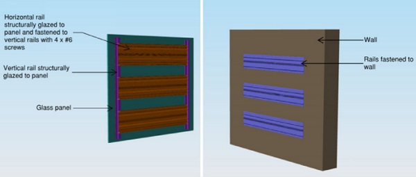
The patented glass panel mounting system consists of an opacified glass panel (2 x 1/4” with PVB interlayer) with extruded aluminum horizontal and vertical rails. The assembly is then secured into place via horizontal rails fastened to the backup structure. The rails are bonded to the back of the glass panel with structural adhesive.
The vertical rails are fastened to the ends of the horizontal rails with #10 screws. The vertical rails ensure that the dead load of the glass panel is shared equally between the rails. However, the dead load of the full assembly is assumed to be supported on the upper rail which is fixed to the backup structure.
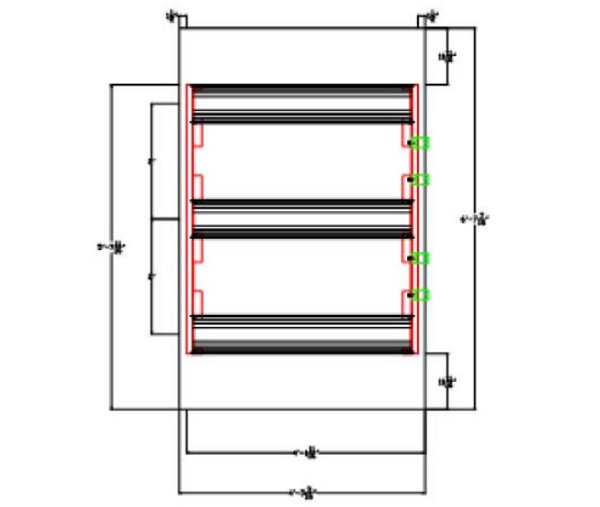
All weight of the laminated glass panel must be able to be carried on one rail although multiple rails are used for attachment [Figure 8].
Loads and Code
In order to analyze the Dead Loads are based on member self-weights using the following densities:
• Aluminum 170 lbs / ft3
• Glass 157 lbs / ft3
The glass panel is assumed to have the following build-up:
• 1/4” AN glass + 0.06” PVB interlayer + 1/4” AN glass 7 psf
According to the building code of the jurisdiction, glass partitions are designed for the following loads:
• Live Load = 50 plf applied at 3’6” ht
• Interior Wind Load allowance (ASD) 5 psf
In keeping with the building type, number of stories, location, and occupancy category:
• Occupancy Category III
• Mapped MCE spectral response at short periods, SS = 1.500g
• Mapped MCE spectral response at 1-second period, S1 = 0.600g
• Site Class (high rise, deep foundation) C
• Seismic Design Category = D
• Lateral Seismic Load, Fph = 0.3G
• Lateral Seismic Load, Fpv = 0.2G
Load combinations (ASD)
• LC1: D
• LC2: D+ W
• LC3: D+ 0.7E
• LC4: 0.6D + 0.7E
The seismic load effect, E, is established by combining the three orthogonal directions of loading considering 100% of the load in one direction with 30% in the other directions:
• E = (±Ex) + (±0.3Ey) + (±0.3Ez)
• E = (±0.3Ex) + (±Ey) + (±0.3Ez)
• E = (±0.3Ex) + (±0.3Ey) + (±Ez)
Building Movement
Since the panels are attached to interior walls, there is no vertical differential deflection to accommodate. For inelastic seismic drift of the building, the code limit allowable story drift of 0.015H is assumed and is superimposed onto the panel support.
Glass design parameters and load duration factors were per ASTM E-1300. All vertical and sloped glass is designed with a probability of breakage of 1 in 1000.
Structural Adhesive Design
- Under short term loads, allowable tension stress or shear stress shall not exceed 20 psi.
- Under long term loads, allowable stress shall not exceed 1 psi.
- When fully finite element analysis is performed, higher allowable stresses can be used as follows:
- Short term allowable tension or shear shall not exceed 24 psi.
- Long term allowable shear or tension stress shall not exceed 2 psi.
- Structural adhesive bite is assumed to be 1” wide with a ¼” glueline
- Shear modulus, G 0.5 MPa = 72.5 psi
- Young’s modulus, E 2.4 MPa = 348.1 psi
Results
Long Term Load condition:
• Under DL: Max. tension to SSG element = 0.012lbs with 0.026lbs shear
• Element effective area = 0.25” x 0.25” = 0.0625in2
• Tension element stress = 0.20psi with 0.42psi shear
Per Dow Corning for use with FEA analysis:
• Allowable long-term tension = 0.015MPa = 2.17psi
• Allowable long-term shear = 0.015MPa = 2.17psi
• Overall utilization = (0.20/2.17)2 + (0.42/2.17)2 = 0.06 < 1 – OK
Short Term Load Condition:
• Under D+WL: Max. tension to SSG element = 0.041lbs with 0.03lbs shear
• Element effective area = 0.25” x 0.25” = 0.0625in2
For mechanical retention system:
• Max. shear = 125lbs < Allowable shear = 197lbs
• Max. tension = 42lbs < Allowable tension = 198lbs
• #10 Screw per clip to backup wall is adequate (screws must engage at stud)
All parts of the system checked out from the finite elements analysis and were well below maximum values allowable by materials, manufacturer, or code.
Plug and Play
The resulting “plug-and-play” system uses modular parts in different configurations to meet each building project’s unique needs. The system was designed to align glass and wall mounts within plus or minus five thousandths of-an-inch (+/- 0.005”) tolerance. The minimum reveal allows removal and replacement as well as provides for movement and the means for future seismic anchorage.
With most new construction becoming modularized with all elements being fabricated in shop, a safety-engineered mounting system offers building owners, architects and glaziers more peace of mind. It had been utilized as a proven, unitized, interior glass-mounting system but could it hold up to seismic testing?
The Test
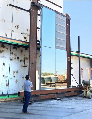
On the day of the test, under the full-on blazing sun, 107-degree desert, the location looked like a Hollywood movie set was transported to Fresno, CA - building façades lining a mock street. It was almost like walking into a Clint Eastwood movie where you hear that telltale whistle of a Western gunfight as the test apparatus [Figure 9] was approached. On that hot summer day in July 2018, over 1,200 pounds of glass towered 20 feet above. The doctor of testing hit the start button and an earthquake started shaking the ground.
The test subjected half a ton of 9/16”-thick, mirror-backed, laminated glass to among Mother Nature’s worst - a massive earthquake - to allow objective observation of how the mounting system fared under such abuse. The glass had to stay on the wall, and any cracks or imperfections resulting from the seismic event could not allow even 1 square inch of material to fall from the wall – or the test would be over
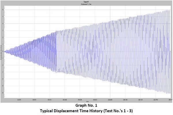
The Big Reveal
At the Fresno testing site, a 50-horsepower hydraulic pump started to swing the glass back and forth [Figure 10] in intervals of mere seconds, not stopping for a full six minutes. The continuous movement of the American Architectural Manufacturers Association (AAMA) test simulated the conditions of increasingly severe earthquakes. There is no expectation of success or failure – there is only waiting. The glass moves left to right at the bottom, back and forth, first a half-inch, then an inch, all the way up to six inches. The observers wait for a screw to come out of the wall or the glass to crack.
Just 15 screws held each four 4-foot-by-10, 300-pound glass panels in place, a setup that had taken the test crew less than 15 minutes to install once they were briefed on the system. Could the system withstand earth-shaking conditions? Then the test ended. Everything - the glass and the mounting system - stayed on the wall. No glass panels pushed against each, and nothing got broken or chipped.
AMAA 501.6 Compliant
After the successful test through the Intertek facility in Fresno, CA, the mounting system, also known as CaptiveHook®, became the only multi-piece decorative glass wallmounting system on the market to earn the distinction of being seismically rated AMAA 501.6 compliant [Figure 11].
The patented mounting system met the architectural and structural constraints while accommodating some of the highest seismic loads and inelastic seismic movements in the world using seismic restraint mechanisms. The AAMA certification confirms the performance of the system.
The finite element analysis performed by Eckersley O’Callaghan indicated that the system would significantly exceed the resilience necessary to weather the stress and strain the g forces imposed. On the ground dynamic testing objectively supported the calculations and modeling of the materials and system design.
References:
[1] Lorant, G., FAIA. (2016, October 11). Seismic Design Principles. Retrieved April 25, 2019, from https://www.wbdg.org/resources/seismic-designprinciples
[2] Performance of non-structural systems. (n.d.). Retrieved April 25, 2019, from http://www.seismicresilience.org.nz/topics/non-structuralsystems/performance-of-non-structural-systems/
[3] Arnold, C., FAIA, RIBA. (2016, October 11). Seismic Safety of the Building Envelope . Retrieved April 25, 2019, from https://www.wbdg.org/resources/seismic-safety-building-envelope
[4] Briefing Paper 5 Seismic Response of Nonstructural Components. (n.d.). Retrieved April 25, 2019, from https://www.atcouncil.org/pdfs/bp5a.pdf
[5] The Seismic Behaviour of Curtain Walls: An Analysis Based ... (n.d.). Retrieved April 25, 2019, from https://www.degruyter.com/downloadpdf/j/mmce.2013.9.issue-4/mmce-2013-0013/mmce2013-0013.xml
[6] The Importance of Building Codes in EarthquakeProne ... (n.d.). Retrieved April 25, 2019, from https://www.fema.gov/media-library-data/1410554614185-e0da148255b25cd17a5510a80b0d9f48/Building Code Fact Sheet Revised August 2014.pdf
[7] Curtain Wall Testing. (n.d.). Retrieved April 26, 2019, from http://www.intertek.com/building/curtainwall-testing/
[8] Dhanani, S. L. (2013, April). Seismic Response of Non-Structural Elements - IJIET. Retrieved from http://ijiet.com/wp-content/uploads/2013/05/37.pdf
[9] Thompson, K. D. “Earthquake Risk Reduction in Buildings and Infrastructure Program.” NIST, 11 Mar. 2019, www.nist.gov/programs-projects/earthquakerisk-reduction-buildings-and-infrastructureprogram.
[10] Memari, A. M., Shirazi, A., & Kremer, P. A. (2007). Static finite element analysis of architectural glass curtain walls under in-plane loads and corresponding full-scale test. Structural Engineering and Mechanics, 25(4), 365-382. https://doi.org/10.12989/sem.2007.25.4.365
[11] Stelzer, I. “SentryGlas®—High-Performance Laminated Glass for Structural Efficient Glazing.” Structures & Architecture, 2010, pp. 91–92., doi:10.1201/b10428-41.
[12] So, A., & Chan, S. “Stability and Strength Analysis of Glass Wall Systems Stiffened by Glass Fins.” Finite Elements in Analysis and Design, vol. 23, no. 1, 1996, pp. 57–75., doi:10.1016/0168-874x(95)00023-m.
[13] Bennison, S., HX Qin, M. & Davies, P. (2008). High-performance laminated glass for structurally efficient glazing. Innovative Light-weight Structures and Sustainable Facades.
[14] Pariafsai, Fatemeh. “A Review of Design Considerations in Glass Buildings.” Frontiers of Architectural Research, vol. 5, no. 2, 2016, pp. 171–193., doi:10.1016/j.foar.2016.01.006.