Challenging Glass 6
Conference on Architectural and Structural Applications of Glass
Louter, Bos, Belis, Veer, Nijsse (Eds.), Delft University of Technology, May 2018.
Copyright © with the authors. All rights reserved.
ISBN 978-94-6366-044-0, https://doi.org/10.7480/cgc.6.2183
Authors:
Vincenzo Mamone, Gerardo Masiello, Luca Difonzo

After its final closure, almost 15 years ago, the new owners decided to refurbish the building and to convert it into a shopping center. The entire project was developed with particular attention to the conservation of the building style. I n order to join the ground level to the former gallery level a new steel staircase has been placed and three laminated glass balustrades were added. The bigger one is a big rectangular glazing 4047 long and5765 mm high consisting of 8 rectangular laminated glass panels, each composed of two 12 thick fully tempered glass sheets laminated with PVB interlayer.
Unique steel connections were designed and built in order to join the glass panels to each other and to the steel staircase. The connections to the staircase were designed so to avoid the out-of -plane movements of the glass panels, and to allow the free vertical relative movement between staircase and glass. The horizontal out-of -plane movements of the top edge of the big glazing is prevented owing to a horizontal 5600 mm longlaminated glass fin. The paper illustrates the design and check of the glass panels, their geometry and functioning, the numerical analyses and the results.
1. Introduction
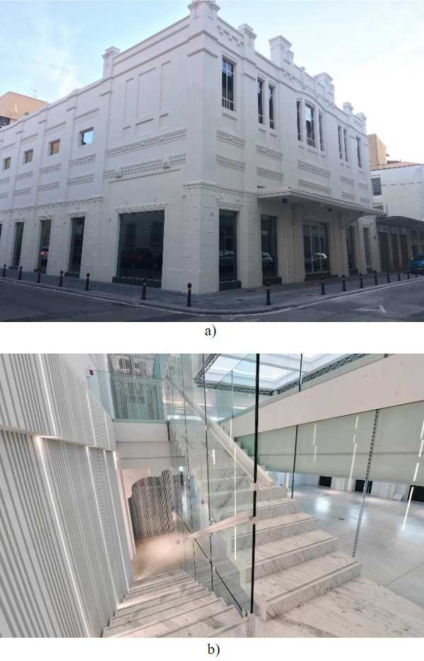
The Teatro Margherita in the city of Livorno in Italy was built and opened in 1913, see figure 1a. It was one of the first cinemas of the city but unfortunately during the last decades of the century was progressively abandoned and definitely closed almost 15 years ago. Recently the building was bought by a private business that decided to completely refurbish it and to convert into a shopping center.
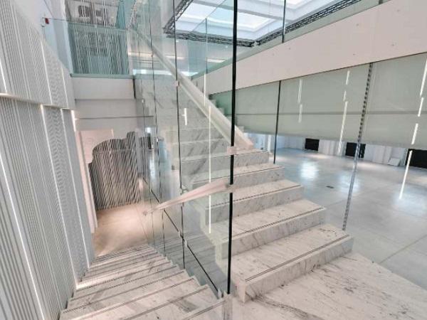
The design managed by the architect Luca Difonzo was developed by paying attention to the architectural and historical value of the building and by preserving its internal decorations and artistic details. In order to join the ground floor level to the gallery level a new double flight open string steel staircase was designed, see figure 1b. The staircase is completely covered by marble and all parapets are made of laminated glass panels joined together, as well as to the threads, to the slab and to the masonry, by means of specific designed steel connections.
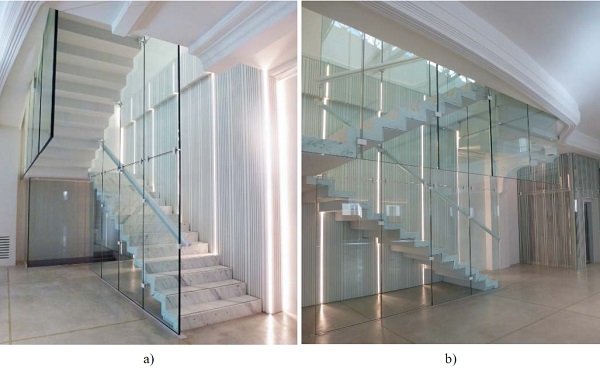
The main request of the architect was to have all the parapets completely transparent with no steel and aluminum frames, figures 2a) and b).
2. Description
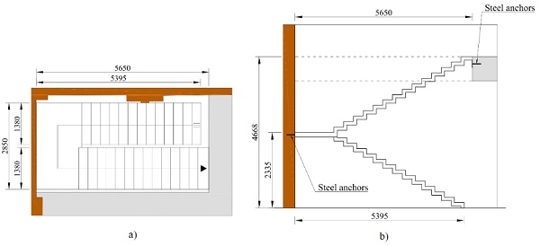
The steel staircase has an elevation of 4668 mm with a length of the lower and top staircases respectively of 5395 mm and 5650 mm, figures 3a) and 3b). The staircase is joined to the existing masonry and to the first level slab by means of steel anchors.
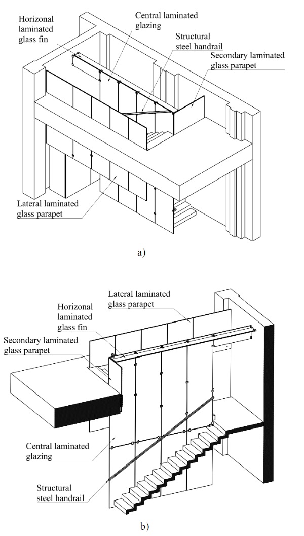
All glass elements are laminated and connected together and to the staircase by means of specific steel joints designed and build for the project. Figure 4a) and b) show 3D views of the staircase with indication of the glass elements and their position:
- Central laminated glazing
- Horizontal laminated glass fin
- Lateral laminated glass parapet
- Secondary laminated glass parapet
The steel staircase had been installed before the glass elements. For this reason it was not possible to have the central glazing made of 5770 mm high panels. It was decided to divide horizontally the central glazing and to join it to the staircase by means of joints in order to ensure out-of-plane constraints to the glass.
The joints between the treads and the glass panels exert an out-of-plane restrain for the glass elements. They are designed in order to allow the free vertical and horizontal deflection of the staircase in the plane of the glass. Henceno forces are transferred from the staircase to the central glazing and to the lateral parapet.
In order to avoid any local dangerous contact tension peak in glass polyethylene elements have been placed between glass and steel.
2.1. Central laminated glazing
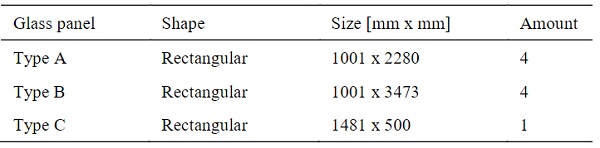
The central glazing is made of nine laminated glass panels, each consisting of two 12-mm-thick fully tempered glass (FTG) layers laminated using 1.52 mm PVB interlayer. All are rectangular of different sizes, 1001x2280 mm, 1001x3473 mm and 1481x500 mm, see figure 5b).
Table 1: Position of the laminated glass panels in the central parapet.
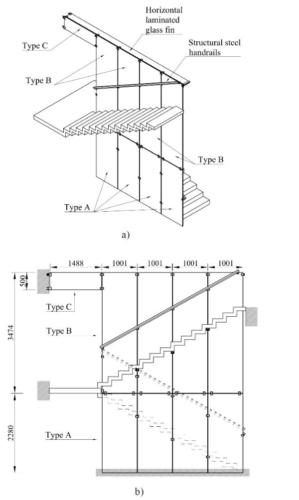
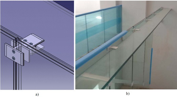
The bottom horizontal edges of the laminated glass panels Type A are inserted into a continuous horizontal split in the ground floor, figure 5b). The top horizontal edges of the laminated glass panels Type B and C are joined to an horizontal laminated glass fin that avoids the out-of-plane motion of the top edges, figures 6a) and b). The two handrails consist of L shape steel profiles covered by wood. Their function is structural because they distribute the imposed horizontal load and reduce the out of plane deflection of the glass due to that load. The handrails are connected to the glass by means of steel clamp connections, figure 9b).
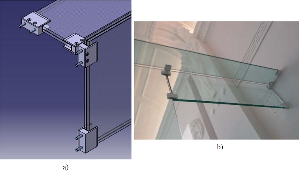
The outer vertical side of the laminated glass panel Type C is connected to the existing masonry wall by means of two clamp joints, figures 7a) and b).
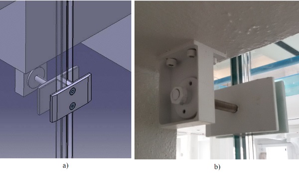
The laminated glass panels are connected to the treads by means of 6 tread-to-glass joints, figures 8a) and b)
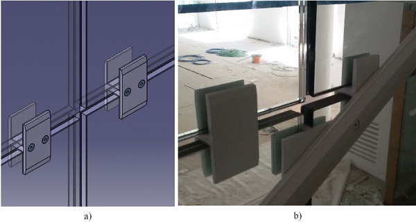
All the glass panels are joined together by means of 9 glass-to-glass steel joints, figures 9a) and b). The vertical side of the glass panel Type B near to the landing is joined to it by means of a steel joint that avoid the horizontal in plane movement of the glass.
2.2. Laminated glass fin
The horizontal laminated glass fin has a length of 5555 mm and a height of 250 mm. It consists of two 12-mm-thick fully tempered glass (FTG) layers laminated using 1.52 mm PVB interlayer.
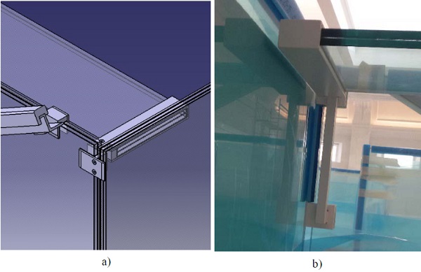
The glass fin carries the horizontal imposed load from the top edges of the glass panels of the central glazing and transfers it to the masonry wall on one side, figures 7a) and b), and to the lateral laminated glass parapet at the other side, figures 10a) and b). No holes were made in the glass and all connections are clamped fixings specifically designed, figure 6a).
2.3. Lateral laminated glass parapet
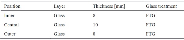
The lateral parapet is made of four rectangular laminated glass panels, each consisting of three fully tempered glass (FTG) layers laminated using 1.52 mm PVB interlayer, see figure 11a).
Table 2: Composition of the lateral laminated glass parapet.
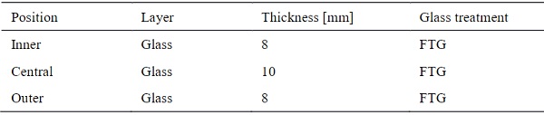
Table 3: Position of the laminated glass panels in the central parapet.
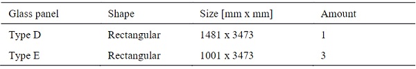
All the four laminated glass panels are joined to the first level slab by means of mechanical fixings, as shown in figure 11b). Any contact between glass and steel is avoided by putting polyethylene elements.
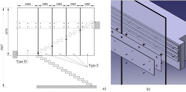
The vertical edges of the panels are joined to each other and to the treads by means of four steel joints that exert an out of plane restrain for the glass elements and allow the free vertical deflection of the staircase, so no in-plane forces are transferred from the staircase to the glass parapets, see figures 8a) and b).
2.4. Secondary laminated glass parapet
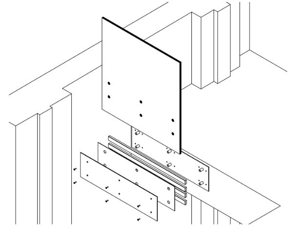
The secondary parapet is a rectangular laminated glass panel 1675 mm long by 1700 mm high. It consists of three glass layers laminated using 1.52 mm PVB interlayer, see Table 4 for thickness and thermic treatment.
Table 4: Composition of the central laminated glass parapet.
The parapet is joined to the first level slab by means of mechanical fixings, as shown in figure 12.
3. Design
3.1. Loading
All the glass elements have been designed according to the Italian construction regulations (NTC 08, 2008) and Italian technical recommendations (CNR-DT 210/2013, 2013) which give a characteristic value of 2.0 kN/m2 as imposed horizontal load acting on the handrails and on the top edges of both the small and lateral laminated glass parapets.
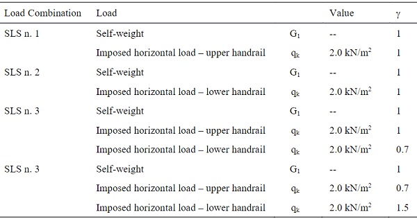
The paper focuses on the design of the central laminated glass parapet and the ULS and SLS load combinations with the leading horizontal load action are considered, see Tables 5 and 6.
Table 5: ULS Load combinations.
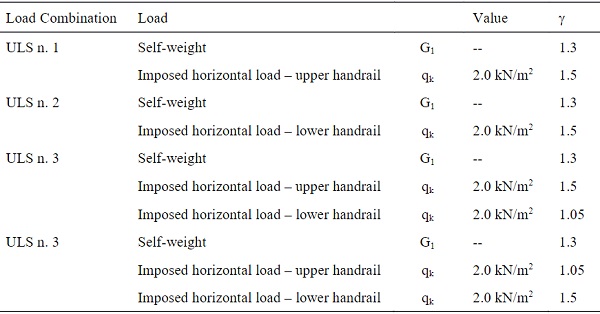
Table 6: SLS Load combinations.
The fail-safe requirements are satisfied trough the hierarchy and the redundancy guaranteed by using laminated panels made of multiple glass layers (Haldimann et al. 2008). The failure of one glass layer of a panel does not cause the breakage of the other glass layer and the collapse of the glazing. All the laminated glass panels are designed by assuring that in case of the breakage of a glass layer the other intact glass layer carries the loads safely. Furthermore,the structural handrails redistribute the imposed horizontal load to the other intact panels. 64 numerical analyses havebeen performed assuming that independently each glass layer of each laminated glass elements is broken; in this case, the stiffness of the failed layer is reduced to about 10% of the original value.
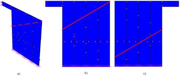
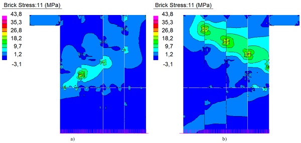
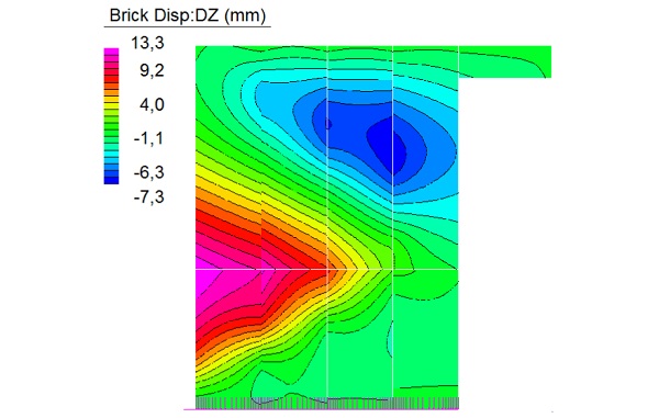
3.2. Numerical modelling
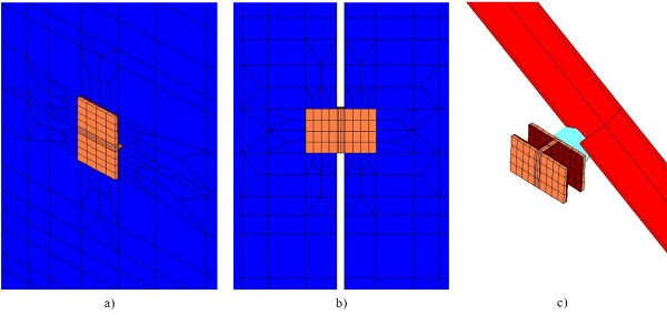
In order to design the glazing, a 3D numerical model has been created with the Strand7® Finite Element Software using solid continuum elements, see figures 13a), b) and c). The structural response of all the 9 glass panels has been investigated. taking into account the presence of the handrails as connected to the glasses. The steel joints and the polyethylene gaskets between steel and glass are modelled too, see figures 14a), b) and c). The presence of the horizontal laminated glass fin has been omitted and it has replaced by restraints. The structural behavior of the glass has been investigated separately by means of a specific 3D numerical model. The model was used to evaluate the global behaviour and structural response of the entire structure in terms of stresses in the glass and of deflection and reaction forces at the external supports.
The PVB interlayer has been assumed as linear elastic material, its mechanical properties have been determined according to Bennison et al. (1999) and Van Duser et al. (1999). A value of 2.55 MPa for the Young’s modulus and of 0.499 for the Poisson’s ratio has been adopted, related to a temperature of 30°C and load duration of 30 sec.
The polyethylene has been assumed as a linear elastic material having a Young’s modulus of 10 MPa and a Poisson’s ratio of 0.449.
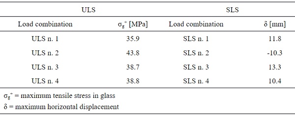
3.3. Results
Table 7 lists the maximum horizontal displacement obtained from the SLS load combinations and the maximum values of the tensile from the ULS load combinations. The presence of the glass railings reduces the horizontal deformability of the glazing.
Table 7: Maximum values of stresses and horizontal displacement in glass.
4. Conclusions
A 5765 mm glass wall was installed to act as both parapet and partition of the staircase joining the levels of former theatre 'Margherita' in Livorno, recently converted to a shopping center.
Since installing full-height panels was not possible, the wall was split in two rows of panels one on top on another, thus making it a hypostatic structure. As the main force acting on the wall is the horizontal thrust, the required restraint was created joining the wall to the steel staircase, while the upper side was restrained with a horizontal glass stiffening fixed to the wall extremities.
The high deformability of the steel structures, though, required the designers to consider minimum assembly tolerance and design tailor-made joints. Such minimum assembly tolerance also required an approach based on parametric CAD design, in order to define the exact position of the fixings to the stairs, to the walls and between the glass panels.
The static loads were also considered for a panel breakup situation, which was taken into account to evaluate the influence on the wall as a whole.
References
Bennison S. J., Jagota A., Smith C. A.: Fracture of Glass/Poly(vinyl butyral) (Butacite®) Laminates in Biaxial Flexure. J. Am. Ceram. Soc., 82 [7] 1761-70 (1999).
CNR-DT 210/2013: Istruzioni per la Progettazione, L’esecuzione ed il Controllo di Costruzioni con Elementi Strutturali di Vetro, CNR, Rome, Italy (2013).
Haldimann M., Luible A., Overend M.: Structural Use of Glass, IABSE-AIPC-IVBH, Zurich, Switzerland (2008).
NTC 08: Norme Tecniche per le Costruzioni, D.M. 14/01/2008, Ministero delle Infrastrutture e dei Trasporti, Rome, Italy (2008).
Van Duser A., Jagota A., Bennison S. J.: Analysis of Glass/Polyvinyl Butyral (Butacite®) Laminates Subjected to Uniform pressure. J. Eng. Mech. - ASCE, 125 [4] 435-42 (1999).