
This paper was first presented at GPD 2025.

Authors:
- Joan Tarrus
- Julian Hänig
sedak GmbH & Co. KG, Einsteinring 1, 86368 Gersthofen, Germany
Article Information
- Published by Glass Performance Days, on behalf of the author(s)
- Published as part of the Glass Performance Days Conference Proceedings, June 2025
- Editors: Jan Belis, Christian Louter & Marko Mökkönen
- This work is licensed under a Creative Commons Attribution 4.0 International (CC BY 4.0) license.
- Copyright © 2025 with the author(s)
Abstract
This paper presents a groundbreaking technological development in the optical quality of tempered glass. For decades, scientists and glass experts have sought to minimise anisotropies – visible iridescence and optical distortions commonly referred to as leopard spots – in tempered and heatstrengthened glass. Despite significant efforts, achieving a true solution remained elusive. Anisotropy inline scanners have advanced the industry's ability to quantify optical retardation across the glass surface, enabling precise detection of these strain-related distortions. However, while such scanners help measure and categorise anisotropies, they do not offer a means to eliminate them, leaving end clients, designers, and façade experts to grapple with the visual impact of strained glass. The most advanced specification in this field, DIN SPEC 18198, classifies optical quality into three classes (A, B, and C), with class A representing the highest standard. Yet even class A glass often exhibits visible strain patterns under polarized light, which can detract from its aesthetic and functional value. After years of intensive research and investment, we are proud to introduce a technological breakthrough that eliminates visible anisotropies in tempered glass, including both flat and curved formats by means of lamination bending down to approximately 7-9 metres radii. This breakthrough represents a significant advancement for many architectural applications. Initially, our research focused on uncoated glass, where the results were extraordinary. Furthermore, coatings applied after the heat-treatment process enhance the optical properties even further, broadening the scope of applications. Curved geometries, often favoured by architects for innovative building designs, benefit immensely from this development. Relaxed curves, combined with the mechanical advantages of tempered glass, are now achievable without the visual drawbacks of anisotropies. This advancement paves the way for a new era in glass façades, where optical perfection meets structural performance.
1.Introduction
Architecture keeps raising the bar when it comes to the most praised and visible element in a building. Glass has become the canvas for the boldest visions. It is no longer just transparent: it is luxurious, protective, transformative, and it has to be sustainable. Project stakeholders seek perfection, where glass, while retaining all its functions, visually disappears.
While maintaining our focus on the core features and functions of the material, we have refined the optical purity of glass to move forward and create new standards of quality.
When specifying glass in buildings, anisotropies (Pasetto et al., 2015, Dehner & Schweizer, 2015, Dix, 2024), along with roller-wave distortions, represent two of the main challenges. While the latter can be managed by fine-tuning ovens – adjusting temperature, quenching speed, and other factors – the socalled “leopard spots,” which result from light retardation due to induced surface tensions and are visible under certain lighting and viewing conditions, are accepted by all major international standards. These standards describe them as a “characteristic” (ASTM C1048) or a “visible effect” (EN 1863, EN 12150, EN 14179).
Today, after years of research and investment, anisotropies in both fully tempered and heatstrengthened glass can be eliminated. This outstanding breakthrough provides a solution for all flat glass applications where iridescence may be an issue. The same technological solution can also be applied to curved glass structures, when radius allows (generally above 8 meters), by toughening the glass in a flat format, bending it to desired geometry afterwards during the lamination in autoclave using structural interlayers that retain the geometry achieved.
2. Anisotropies in glass
2.1. Origin
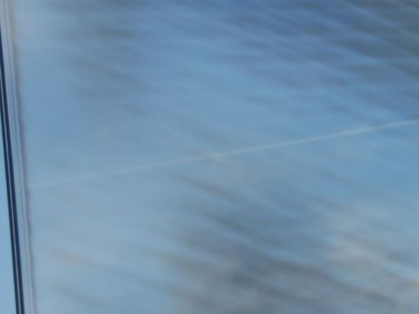
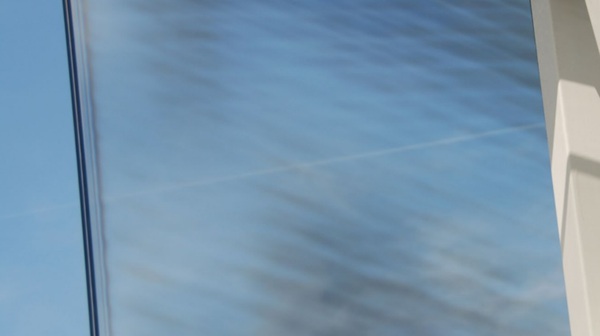
In general, float glass is deemed optically isotropic as a consequence of the protracted annealing process inherent to its production in the float line. Therefore, light is transmitted uniformly, since the refractive index of light rays is identical in every direction (Greek: "isos" = equal; "tropos" = direction, rotation). However, internal stresses manifest themselves in different physical properties in different directions, thereby rendering the glass "anisotropic". The passage of polarised light through a stressed glass medium gives rise to the phenomenon of birefringence, characterised by the occurrence of double refraction. This results in the refraction of light and subsequent dispersion at varying velocities. Consequently, there is visible interference colouration, known colloquially by the designation "leopard spots" (figure 1).
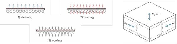
The most common approach to strengthening architectural glass is thermal toughening. The glass is heated above its glass transition temperature (Tg) and subsequently rapidly cooled while oscillated. It is not possible to execute a complete homogeneous heating process. It is evident that the presence of varying roller contact, in conjunction with the presence of boreholes, corners, and edges, results in an uneven distribution of heat throughout the overall glass. The controlled cooling process, facilitated by a high airflow rate, results in the formation of additional traces, a phenomenon known as the Aronen Effect. This effect refers to the variation in glass temperature before cooling and the cooling rate on residual stresses in tempering. The resultant induced internal stress state (figure 2) is the cause of stress birefringence, which in turn leads to undesired anisotropies. The stress state is "frozen" into the glass and will remain unchanged throughout its service life.
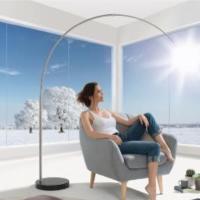
2.2. Optical perception of anisotropies
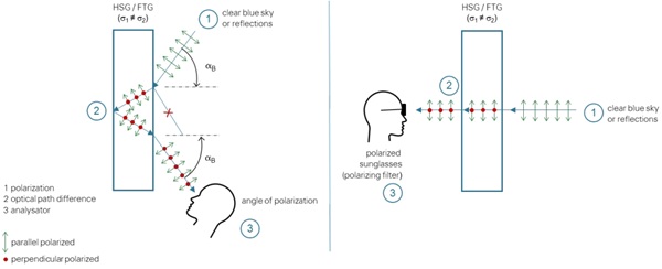
The optical perception of anisotropies by the naked eye is highly influenced by lighting conditions and viewing angle (figure 3). Anisotropies manifest as pronounced visual phenomena in proximity to the Brewster angle, where polarised light is transmitted uniformly without any incidence of reflection. Reflective surfaces, such as bodies of water or areas covered in snow, have been shown to increase polarised light in the atmosphere and the perception of visible anisotropies. The prevailing meteorological conditions and the angle of the sun's positioning also exert a substantial influence. When the sky is bright blue and the sun is low in the sky, the proportion of polarised light also increases significantly. Furthermore, polarised sunglasses (i.e. those equipped with a polarising filter) have been shown to enhance the visibility of anisotropies (Dix 2015, Dehner & Schweitzer 2015).
The intensity of anisotropies is significantly influenced by the thickness of individual glass panes and the number of layers of glass. Furthermore, glass with more complex geometries – such as acute angles, holes, or machined cutouts – tends to exhibit a higher intensity of iridescence phenomena due to more non-uniform heating and cooling. Consequently, the tempering of larger and more complexshaped glass panes is more challenging without introducing a multitude of anisotropies. In laminated glass, the interlayer material can also influence the overall anisotropy of the panel. (Dix et al. 2022).
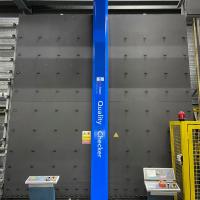
2.3. Quantification by Inline Scanners
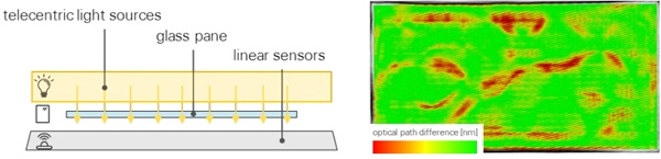
The quantification of anisotropies in glass is achieved through the utilisation of inline scanners, utilising the principle of a calibrated polarimeter (equation 1). The use of image-based technology in conjunction with telecentric light sources, emitting light at different wavelengths, enables the provision of real-time data to operators of tempering furnaces (figure 4). The optical retardation over the entire surface is analysed for each individual pixel based on the imaging data, with the stress optics law being applied in the process. (Softsolution 2023, Ramesh & Vivek 2016)
![]()
s - optical retardation
C - material stress fringe constant
σ1/2 - principal stresses
z - material thickness
The optical retardation (optical path difference) specify the difference in stress levels over the surface and quantify the probability of anisotropies over the entire surface. Coatings or frits absorb or reflect the light rays and do not allow for proper quantification of anisotropies.
2.4. Evaluation according to standards
Current standards for thermally toughened glass such as EN 1863, EN 12150, EN 14179 and ASTM C1048 define anisotropies as “strain patterns” or “stress zones” that “[…] may become visible under certain lighting and other conditions.” (ASTM C1048). However, anisotropy “[…] is a characteristic […] should not be mistaken as […] a defect” (ASTM C1048). Accordingly, as established within relevant standards, anisotropies must be accepted.
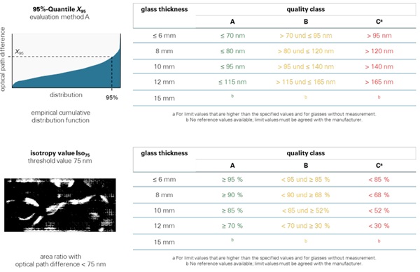
The DIN SPEC 18198 and ASTM C1901 provide guidelines for measuring optical anisotropy, which is a prerequisite for the quantification of anisotropies in glass. Furthermore, DIN SPEC 18198 offers an assessment by means of categorisation of the evaluated data. The methodology encompasses a synopsis of the aggregate retardation for the designated evaluation area, excluding cutouts, edges, and drill holes. Method A of DIN SPEC 18198 is defined as the 95th percentile X95 value of the empirical cumulative distribution function, which quantifies a single value for the purpose of assessment. Method B quantifies the isotropy value Iso75 in percent, where the area ratio with optical path difference <75 nm is quantified. The threshold value of 75 nm has been identified in the extant literature as the point at which anisotropies become discernible to the naked eye (Dix 2024, Dehner & Schweizer 2015).
Based on the evaluation the glass can be categorised into quality classes A, B and C. Figure 5 summarises the classes according to DIN SPEC 18198. This represents a suitable guide for reproducible assessment and reliable reports for customers.
Furthermore, an alternative texture analysis method can be employed to evaluate the homogeneity of optical retardation (Dix 2015) and assess anisotropy. However, this method has not yet been incorporated into the software of commercial scanners.
The standards delineate a methodology for quantification and classification; however, they do not address the elimination of anisotropies. Even at the highest grade, designated quality class A, anisotropy patterns may become visible and thereby compromise the appearance of architectural glass facades.
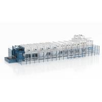
3. sedak tempered+ glass without visible anisotropies
In order to meet the requirements of architects and designers for smooth, undisturbed façades, sedak has introduced a new technology for the uniform tempering of flat glass, with a view to overcoming visible anisotropies. Consequently, anisotropies are no longer perceptible to the human eye (figure 6).
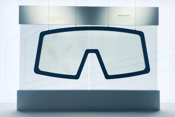
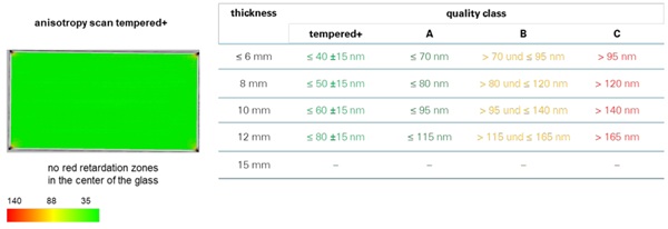
A novel quality class for sedak tempered+ (see figure 7) defines the maximum allowable retardation value X95 in accordance with evaluation Method A (DIN SPEC 18198). As demonstrated by Anisotropy scans, the lowest optical retardation is exhibited by the subject under investigation, thereby outperforming Class A glass. Consequently, anisotropies are rendered visually undetectable. The application of coatings can be executed either before or after the tempering process, with the objective of optimising optical and performance outcomes. This facilitates the realisation of uninterrupted visual perspectives for customers through the glass.
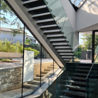
4. Curved glass without anisotropies
At present, the production of anisotropy-free tempered glass is confined to flat tempering furnaces. It is evident that the complexity of bending furnaces is significantly increased, which introduces increased stress patterns due to the higher temperatures that are required and the more varied cooling zones. Consequently, the generation of curved glass devoid of visible anisotropies continues to represent a substantial technical challenge. Nevertheless, an increase in the demand for high-quality curved glass in the architectural sector is prompting the industry to adopt reliable and precise fabrication methods.
Cold bending (on-site) and lamination bending have been identified as viable alternatives for incorporating tempered glass, which is renowned for its superior, anisotropy-free optical quality, into curved applications. In the process of cold bending, the glass is mechanically fixed into its intended geometry. Conversely, in the process of lamination bending, the desired shape is achieved and stabilised during the lamination process using a structural interlayer. It is evident that both techniques facilitate a broad spectrum of curved applications, encompassing uniaxial and double-curved geometries.
In collaboration with the sedak technical team, engineers and designers are responsible for defining bending geometries and simulating induced stresses in detail. (Muja 2022) and (Fildhuth 2015) are two examples of research conducted in this field. These methodologies facilitate the secure structural design of large-format bent glazing, with dimensions extending up to 3.6 × 20 metres. The allowable curvature is determined by the induced stresses in the glass. For single-curved geometries, linear stress analysis (see equation 2) provides a quick and effective way to assess feasibility. However, multi-curved geometries necessitate advanced finite element method (FEM) simulations to ensure compliance with glass strength.
![]()
σ bending stress
E Young’s Modulus
t glass thickness
r bending radius
4.1. Project examples
Designers and stakeholders are continually demanding optimal performance and visual clarity in architectural glazing. This has resulted in the development of sophisticated bespoke solutions that are designed to eliminate anisotropies, with a particular focus on geometrically complex and highspecification applications. The following two case studies are of particular relevance in this regard and demonstrate application scenarios.
Case Study 1 – Spherical DGUs for the Museum of London Skylights
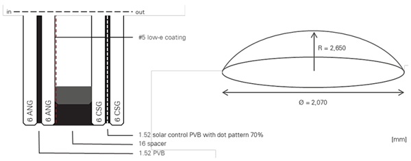
The project required the fabrication of circular, spherically shaped double-glazed units (Ø 2.070 mm) for overhead installation. The outer lite had to meet multiple functional criteria:
- Resistance to climatic loads
- Solar control (via spectral-selective coating and ceramic frit)
- Thermal insulation (low U-value requirement)
Initial options such as annealed glass failed to meet structural safety requirements, while thermally treated glass (heat-strengthened or fully tempered) was ruled out due to manufacturing limitations linked to the geometry.
Solution: A chemically strengthened outer lite was selected, providing enhanced mechanical resistance without inducing birefringence-related anisotropies. Solar protection was implemented by embedding a solar control coating and ceramic frit on the laminated interlayers. For thermal insulation, a low-emissivity coating was applied on face #5 of the inboard lite, comprising a 66.4 slumped, annealed low-iron glass (figure 8).
This configuration ensured mechanical safety, optical homogeneity, and compliance with energy performance requirements — with no visible anisotropies under natural or polarized lighting conditions.
Case Study 2 – Replacement of a Triple-Glazed Curved Façade (Confidential Project)
The client is undertaking a replacement of an existing triple-glazed curved façade where pronounced anisotropies (notably "leopard spots") are evident due to tempering-induced birefringence in the original TGU units. Curved annealed glass was considered as a mitigation strategy, but the thermal stress risk exceeded acceptable thresholds due to solar load and building orientation.
Solution:
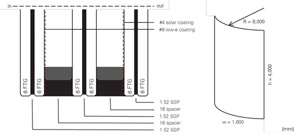
A bespoke lamination-bending process is developed, integrating flat tempered+ glass for no anisotropies (figure 9). The method employs:
- Flat tempering of glass panes using uniform toughening technology staying below the threshold of 75 nm to ensure no presence of any sort of birefringence.
- Bending during the lamination process using high-modulus structural interlayers (e.g., ionoplast) within the autoclave cycle.
- A final build-up consisting of triple IGUs with at least two low-e coated panes and single curved geometry (R8000 mm) achieved without compromising optical purity.
- The result is a mechanically robust, visually homogeneous façade system with negligible anisotropic interference patterns — even under polarized light.
5. Conclusions
Today, the production of curved glass free from visible anisotropies is technically feasible thanks to tailored design and precisely controlled, engineering-validated manufacturing processes. Bending radii as tight as 7–9 meters are achievable, with panel sizes reaching up to 3.6 x 20 meters — far beyond the limits of conventional thermal bending methods. These large-format, optically superior curved glass units are already being implemented in contemporary architectural projects.
The elimination of anisotropies in both flat and curved glass marks a pivotal advancement in glass technology. It enables the realization of high-performance façades and envelopes without optical compromise. Continued innovation in manufacturing and lamination techniques will expand these capabilities, offering architects new freedom in form and performance.
References
ASTM C1048 (2025). Standard Specification for Heat-Strengthened and Fully Tempered Flat Glass. ASTM International.
Dehner H., Schweitzer A. (2015). Thermally toughened glass panes for architectural applications without visible anisotropy. Glasbau 2015. https://doi.org/10.1002/stab.201590096
Dix S. (2022). Investigation of polymeric interlayers in laminated glass using photoelasticity. Glasbau 2022. https://doi.org/10.1002/cepa.1673
Dix S. (2024). A Concept for Measuring and Evaluating Optical Anisotropy Effects. Springer Vieweg. https://doi.org/10.1007/978-3-658-42029-1
EN 12150 (2015). Glass in building - Thermally toughened soda lime silicate safety glass. CEN.
EN 14179 (2016). lass in building - Heat soaked thermally toughened soda lime silicate safety glass. CEN.
EN 1863 (2012). Glass in building - Heat strengthened soda lime silicate glass. CEN.
Fildhuth T. (2015). Design and monitoring of cold bent lamination-stabilised glass: investigated by applying fibre optic sensors. Dissertation ILEK Stuttgart. http://dx.doi.org/10.18419/opus-118
Muja E., Hänig J., Rooprai M., Stelzer I., Weller B. (2022). Cold Bent Laminated Glass Application – Numerical Research. Engineered Transparency 2021. https://doi.org/10.1002/cepa.1857
Pasetto S. (2015). Anisotropy as a defect in U.K. architectural float heat-treated glass, Glass Performance Days 2015.
Ramesh K., Vivek R. (2016). Digital photoelasticity of glass: A comprehensive review. Optics and Lasers in Engineering Vol. 87. https://doi.org/10.1016/j.optlaseng.2016.03.017
Softsolution (2023). Line Scanner technical presentation.


Comments
This is a truly impressive piece of research and an exciting breakthrough for the future of architectural glass. The ability to eliminate visible anisotropies in both flat and curved applications feels like a real turning point for designers and engineers who have long struggled with balancing aesthetics and performance. I especially liked the way the paper connected technical precision with architectural aspirations—it shows how innovation can elevate not only function but also visual harmony in façades.
It’s great to see how companies and research collaborations are pushing these boundaries, much like Cortezza Group does in other areas of advanced building solutions. Developments like this open new opportunities for creating seamless, high-performance architectural environments.