Source:
Challenging Glass 7
Conference on Architectural and Structural Applications of Glass
Belis, Bos & Louter (Eds.), Ghent University, September 2020.
Copyright © with the authors. All rights reserved.
ISBN 978-94-6366-296-3, https://doi.org/10.7480/cgc.7.4484
Authors:
Laura Galuppi a
Gianni Furio Mario Royer-Carfagni a,b
Luca Barbieri b
Massimo Maffeis b
a Department of Engineering and Architecture, University of Parma, Italy
b Maffeis Engineering S.p.A, Italy

Double Glazed Units (DGUs) consist of two glass panes held together by structural edge seals. Calculation methods for DGUs consider that actions applied on one pane develop effects in all the panes, due to the coupling from the entrapped gas. Various methods have been proposed in standards to evaluate this load sharing, which depends upon the stiffness of the glass panes, the thicknesses of spacer and the size of the DGU.
A comprehensive analytical formulation, the Betti’s Analytical Method (BAM), has been recently proposed to calculate the load sharing in DGUs of any shape, composed by glass panes of arbitrary thickness, with various support conditions at the borders and various types of external actions, including concentrated and line loads. Simple expressions can determine the gas pressure as a function of a universal shape function, which coincides with the deformed surface of a simply supported plate, of the same shape of the DGU, under uniformly distributed load.
Here, comparisons are made with numerical analyses, performed by implementing an ad hoc routine in the software Straus7, developed by Maffeis Engineering, where the deflection of the glass panels is iteratively calculated, until the volume enclosed reaches a value compatible with the pressure exerted by the gas. The numerical routine, that is part of an integrated parametric approach to the façades design, allows precise calculations for any kind of build-up,panel shapes and load conditions.
1.Introduction
Insulating Glass Units (IGUs) consist of two or more glass panes, either monolithic or laminated, connected one another by spacers bonded with structural edge seals along their perimeter. The resulting cavity is usually filled with argon, krypton or xenon to reduce heat conductivity and to improve acoustic insulation properties. When composed by two glass plates, they are commonly referred to as Double Glazing Units (DGUs). Due to the interaction between the glass plates and the gas, all the panes share a portion of the loads applied on one pane, either uniform, line distributed or concentrated.
Various methods have been proposed in standards to evaluate the load sharing under uniformly distributed loads (wind, snow, self-weight, variation of the internal pressure with respect to the external pressure). The simpler formulation is the “thickness cubed method” proposed by the American ASTM E-1300. The draft-proposal of European Norm prEN 16612 accounts for the gas compressibility through an insulating-unit factor, tabled for rectangular-shaped IGUs only. A more refined method is that proposed by Feldmeier (1996), that can consider also the case of line distributed and concentrated actions. This method requires to calculate the volume enclosed within the deformed plates under unitary line or concentrated loads.
Recently, Galuppi and Royer Carfagni (2019) have proposed a comprehensive analytical formulation to calculate the load sharing in a DGU of any shape and glass panes of arbitrary thickness, with various support conditions at the borders and general external actions, including concentrated and line loads as particular cases. This formulation, accounting for the gas compressibility, relies upon a tailored use of the classical Reciprocal Work Theorem by Betti in linear elasticity and, hence, it has been referred to as Betti’s Analytical Method (BAM) for DGUs.
Simple expressions can determine the gas pressure as a function of a universal shape function, which coincides with the deformed surface of a simply supported plate, of the same shape of the DGU, under uniformly distributed load. For laminated glass, it has been verified (Galuppi 2020) that the results are accurate if one considers the laminate as a monolith with the deflection-effective thickness, provided it is calculated with the EET method (Galuppi and Royer Carfagni 2012).
Here, comparisons are made with numerical analyses, performed by implementing an ad hoc routine in the software Straus7, developed by Maffeis Engineering, where the deflection of the glass panels is iteratively calculated, until the volume enclosed reaches a value compatible with the pressure exerted by the gas. The numerical routine, that is part of an integrated parametric approach for the design of façades, allows to accurately calculate the load sharing for any kind of build-up, panel shapes and load conditions. Results obtained in paradigmatic examples confirm the accuracy of the proposed analytical approach, for both rectangular and triangular DGU. The comparisons consider also the case of DGUs whose panes are made of laminated glass.
2. The Betti’s Analytical method
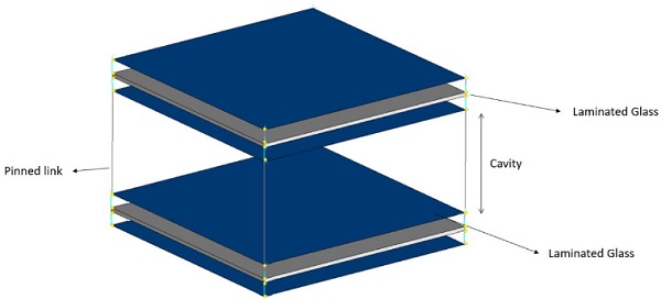
The Betti's Analytical Method (BAM) for the evaluation of the load sharing in DGUs (Galuppi and Royer-Carfagni 2019) relies upon the assumption of linear elastic response of the glass plates, both from the material and the geometrical point of view. No particular hypotheses are made about the type of boundary conditions for the out-of-plane displacement at the borders of the DGU, which can be simply supported, either continuously or point-wise, elastically supported or free. To illustrate the basic equations of the BAM approach, let us consider the DGU of arbitrary shape shown in Fig. 1, formed by glass panes 1 and 2, of thickness h1 and h2, respectively, confining a hermetic cavity of thickness s, filled with gas.
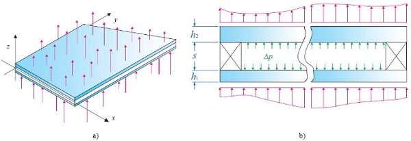
The internal glass pressure p0 in the reference undistorted state is supposed to correspond to the external atmospheric pressure at the time of sealing. When external loads are applied, the reference volume of the cavity V0 may vary, producing a variation Δp of the gas pressure, usually much lower than the atmospheric pressure, which sums up with the applied loads and contributes to the straining of the panes.
2.1. The auxiliary problem
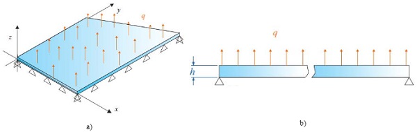
Following BAM approach, Δp may be evaluated by considering the auxiliary problem shown in Fig. 2. This corresponds to a single glass panel of thickness h, with the same shape of the considered DGU, simply supported at its edges, even if the DGU may have diverse boundary conditions, and subjected to a fictitious uniform pressure q.
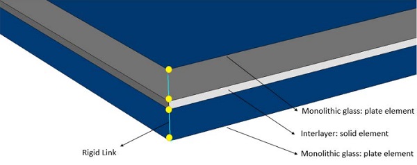
The out-of-plane deflection w(x, y) for simply supported plates of various shapes under uniform loading is recorded in many textbooks. Denoting with A the plate area and with
![]()
its flexural stiffness, the out-of-plane
![]()
where φ(x,y) is a non-dimensional shape function, which depends only upon the shape of the plate. The only quantities that are needed to evaluate the load sharing in DGUs are the mean value of the shape function over the plate area, referred to as φA, its mean value φLon the line L where a line-distributed load is applied, and its value φP at the point of coordinates (xP, yP) where the concentrated load is applied, i.e.,
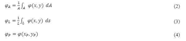
Graphs and tables for the evaluation of these coefficients, for rectangular (with different aspect ratio), equilateral triangular and isosceles right triangular plates are recorded in (Galuppi 2020).
2.2. The load sharing
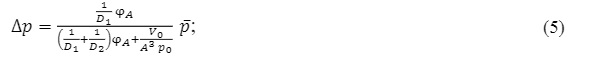
The load sharing is strongly influenced by the flexural stiffness of the panels and the gas compressibility, and it is provided by the pressure variation Δp in the interpane cavity. By considering the DGU of Fig.1 under an external load applied on glass pane 1, Δp can be evaluated with simple formulae for the different-in-kind external loading. In particular, one has that:
- when the DGU is subjected to an external uniform pressure p‾
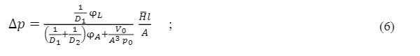
- when the DGU is subjected to a line distributed load H‾, applied on a line of length L,
- when the DGU is subjected to a concentrated load F‾,
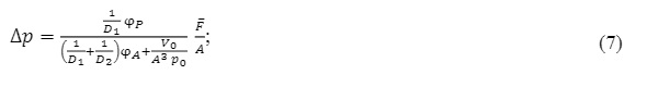
where
are the flexural stiffness of the i-th glass panel. As explained in (Galuppi and Royer-Carfagni 2019), when the gas in the cavity is considered incompressible (isochoric gas transformation), the pressure variation may be evaluated with formulae (5-7) by setting V0/p0= 0.
As discussed in (Galuppi and Royer-Carfagni 2019) and (Galuppi 2020), when the panes are made of laminated glass, D1 and D2 may be calculated by considering the deflection-effective thickness of the panes. Among the various methods for the calculation of effective thickness recorded in the literature, the Enhanced Effective Thickness (EET) proposed in (Galuppi and Royer-Carfagni 2012) seems to be the one providing the best approximation for various geometries.
3. The “Glass Checker” developed by Maffeis Engineering
3.1.General model construction
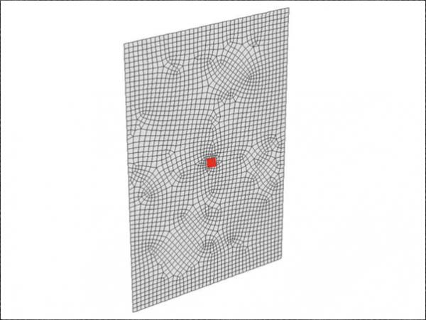
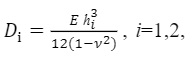
The numerical model is composed by several elements and displacement links between nodes. In order to ensure that the aspect ratio of all the elements remains below acceptable values,the main sizeof the element changes depending on geometry, boundary and loading conditions. The variation of the mesh size follows a user-defined law,which avoid high dimension ratio between close elements. Typical meshes used in load sharing analyses are sketched in the Fig. 3.
3.2. DGU composition
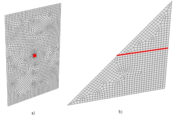
The most general case of DGU composed by two laminated glass elements is sketched in Fig. 4.
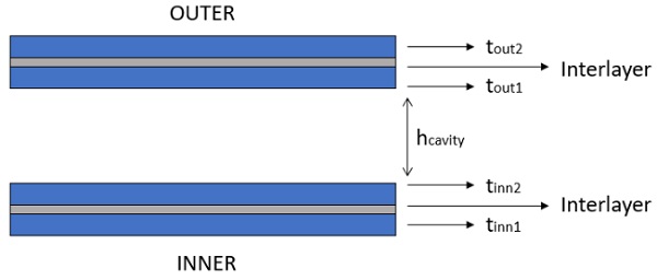
When the glass elements composing the DGU are laminated, they are modelled by using the multi-element section represented in Fig. 5.
In particular:
- The monolithic glass pane is discretized with 4 node shell elements; the mechanical properties of the glass are concentrated in the geometric mid plane of the plate.
- The interlayer is discretized with 8 node solid elements, with the same thickness of the interlayer itself; the main mechanical property of the element is the shear modulus.
- The effective distance between layer is accounted for by means of nodal rigid link; the transport contribution to the global inertia have been considered by using rigid cinematic link between shell and brick elements.
In order to model the effective behavior of the cavity, the two (laminated) glass panes have been connected by using a kinematic element, which allows the relative rotations and links the relative displacement between two nodes. A sketch of this build up is presented in Fig. 6.
3.3. Load sharing Procedure
The numerical iterative procedure is based on the assumption that no gas can be exchanged between the cavity and the external environment. The “Maffeis Glass Checker” considers an isochoric procedure during the load sharing, i.e., the compressibility of the gas is neglected. Under this assumption, a pressure variation is produced under panes deflection; this pressure can be evaluated through numerical iterative analyses, which follow the workflow presented in Fig. 7. Here K1 denotes the stiffness of the directly loaded panel, while K2 is the stiffness of the panel subjected only to the pressure variation.
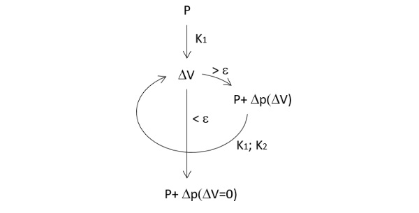
Under a generic loading condition acting on one pane, the cavity is subjected to a volume variation ΔV. The displacement field that produces the cavity volume variation is obtained through a geometric non-linear finite-element analysis, performed with the commercial software Straus7. The Maffeis Glass Checker follows a step-by-step loop procedure in which, following the isochoric transformation law, a volume variation, obtained at a given step, causes a pressure variation of the cavity Δp(ΔV), which will be added to the initial load condition at the following step. The loop continues untill the cavity, which at each step of the loop starts from an undeformed condition, reaches a volume variation small enough (ΔV<ε). Here, the convergence parameter ε has been set equal to 0.1%.
4. Results and Comparisons
Here, the results obtained by using the BAM approach are compared to those obtained by using the “Glass Checker” developed by Maffeis Engineering. Reference is made to both rectangular and triangular DGUs, under both line distributed and concentrated load. The simplest case of DGU under uniform pressure, for which the BAM approach gives results in perfect agreement with the formulation proposed by current Standards, as discussed in (Galuppi and Royer Carfagni 2019), is not considered here. The comparisons are made in terms of both pressure variation Δp in the interpane cavity and of the out-of-plane displacement of the glass elements. In particular, here the external load is supposed to be applied on pane 1, and the maximum deflection of pane 2, subjected only to Δp, is measured.
4.1. Rectangular DGUs
Consider the rectangular DGU shown in Fig. 8, of width a and height b, with cavity thickness s = 16mm and panels thickness h1= h2 equal to 8 mm, 10 mm and 12 mm. The gas pressure at the time of sealing is considered equal to the standard atmospheric pressure, while the cavity volume is assumed to be V0= sA.
4.1.1. Rectangular DGUs subjected to line-distributed load
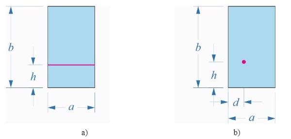
Consider, first, the case of square DGUs 2m x 2m subjected to a line distributed load H‾=1 kN/m applied at a horizontal line at a height h, as shown in Fig. 8a.
Fig. 9a shows the pressure Δp arising in the cavity obtained by means of the BAM approach for both compressible (continuous line) and incompressible (dashed line) gas, as a function of the load location. Notice that, as discussed in (Galuppi and Royer Carfagni 2019), the pressure is the highest in the latter case, and it is independent of the thickness of the glass panels. However, since the glass plates are large and compliant, the influence of the gas compressibility is quite limited in these cases. Notice that, for compressible gas, the higher is the deformability of the constituent plates (i.e., the lower is their thickness), the lower is the influence of the gas deformation and the pressure variation approaches the value corresponding to the incompressible case.
As mentioned in Sect. 3, the Glass Checker by Maffeis Engineering considers isochoric transformation of the gas in the cavity. The nonlinear modelling of the glass plates response results in a slight dependence of the numerically-evaluated Δp on the plate thickness.
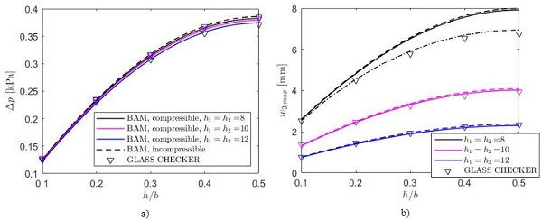
Fig. 9b shows the comparison among the BAM approach and the Glass Checker in terms of the out-of-plane displacement of glass pane 2. It can be noticed that, for panes of thickness 10 mm and 12 mm, there is a very good agreement between the BAM and Glass Checker results, being the mean difference of the order of 2%. On the other hand, for the case h1= h2= 8 mm the geometric non-linear effects are quite relevant, and the BAM approach tends to overestimate the maximum deflection, as shown in Fig. 9b.
This problem may be overcome by using the BAM approach to evaluate Δp, and successively performing FEM analyses, accounting for the geometric nonlinearities, to evaluate the plate deflection. The so-obtained maximum out-of-plane displacement, evaluated by using the ABAQUS program, is plotted in Fig. 9b with dashed-dotted line. This allows to reduce the maximum difference between BAM approach and numerical results from 14.5% to 2.5%.
To evaluate the influence of the plate aspect ratio, now the cases of rectangular DGUs with a=2m, b=3m (line load applied on the shorter side) and a=2 m, b=3 m (line load applied on the longer side) are considered. Since it has been verified that, in these cases, the influence of the gas compressibility is limited, the analytical results are obtained by adopting the BAM approach accounting for the gas compressibility. The results in terms of maximum deflection of plate 2 are plotted in Fig. 10 as a function of the height where the line load is applied, for different values of the plate thickness.
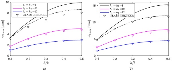
Again, for the case h1= h2= 8 mm, the geometric non-linear effects are relevant, and the BAM approach tends to overestimate the plate deflection. As in the previous case, to account for the geometric non-linearity of the glass plates response, the maximum deflection of plate 2 has been evaluated, a posteriori, also by means of non-linear FEM analyses. The discrepancy between the so-obtained results and those obtained with the Glass Checker is due to the fact that the latter does not account for the gas compressibility effects.
4.1.2. Rectangular DGUs subjected to concentrated load
Consider now the rectangular DGU shown in Fig. 8b, subjected to a concentrated load F=1 kN, applied at a point of coordinates (d, h). As a representative example, here the case of load applied on the plate diagonal, i.e. the case of ℎ/b=d/a, is considered. Fig. 11a and Fig. 11b shows the comparisons, in terms of maximum deflection of plate 2, for square DGU with edge length of 2 m and for rectangular DGU 2 m x 3 m (equivalently, 3 m x 2 m).
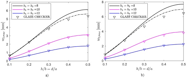
Again, for high values of the glass thickness (i.e., for h1= h2 = 10 mm and h1= h2 = 12 mm), there is a very good agreement between the analytical (BAM) results and those obtained with the Glass Checker, being the mean discrepancy of about 1.8 %. On the other hand, to correctly evaluate the plate response for the case h1= h2 = 8 mm, it is necessary to analytically evaluate the gas pressure, and afterwards to perform numerical analyses to capture the influence of the geometric nonlinearities.
4.2. Isosceles right triangular shape
Consider now the isosceles right triangular DGU shown in Fig. 12, with a = 3 m. Notice that, even if there are many architectural applications in which triangular-shaped DGUs are used, this case is not covered by current Standards(ASTM E-1300, prEN 16612). For this case, graphs and tables for the evaluation of the relevant coefficients φA, φL, and φP, defined by equations (2-4), are recorded in (Galuppi 2020).
As in the previous example, the cavity thickness is assumed to be s = 16 mm, while different values for the panels thickness are considered. Again, the gas pressure at the time of sealing is considered equal to the standard atmospheric pressure, while the cavity volume is assumed to be V0 = sA.
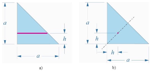
Consider, first, the triangular DGU subjected to a distributed load per unit length H=1 KN/m, appliedon pane 1along a horizontal line at a generic height h, as shown in Fig. 12a. Notice that the length L of the line where the load is applied, which is necessary to evaluate the pressure variation Δp as per eq. (6), corresponds to (a-h). Fig. 13a shows the comparison of the maximum deflection of pane 2, evaluated by means of the BAM approach and with the Glass Checker tool, plotted as a function of h/a, varying between 0.1 and 0.9.
The second considered case, shown in Fig. 12b, is that of a concentrated load F= 1kN applied on the symmetry axis of pane 1, at a distance h from the triangle catheti. The correspondent maximum out-of-plane displacement of pane 2 is plotted in Fig. 13b as a function of h/a, varying between 0.1 and 0.4.
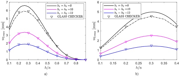
It may be verified that, for both the considered cases, the influence of the gas compressibility is quite low and, hence, the two models provide results in very good agreement, at least for thick glass plies (mean discrepancy of the order of 3 %). On the other hand, for h1 = h2 = 8 mm, the geometric nonlinear effects become relevant, and they can be accounted for by considering the BAM approach to calculate Δp, and later perform a non-linear FEM analysis.
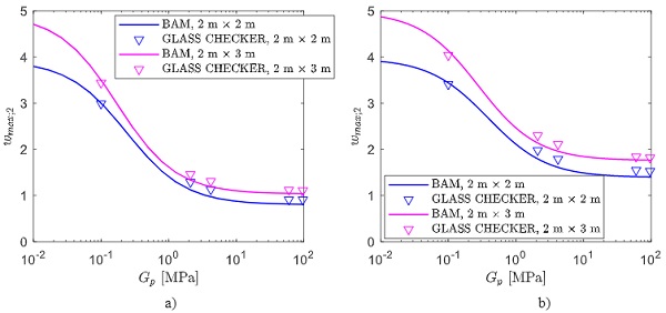
4.3. Rectangular DGUs made of laminated glass
When the panes composing the DGU are made of laminated glass, the BAM formulae may be used by considering an equivalent monolithic plate with effective thickness, which can be accurately evaluated by using the Enhanced Effective Thickness (EET) method for plates (Galuppi and Royer-Carfagni 2012, Galuppi et al2013, 2014). To evaluate the flexural stiffness of a laminated glass panel, the deflection-effective stiffness, which depends upon glass and interlayer mechanical properties and thickness, as well as on plate geometry, boundary and loading conditions, shall be considered.
Since the effective thickness methods establish an equivalence with a monolith only in terms of maximum deflection, there may be a difference at the other points between the deflection of the laminate and that of the equivalent monolith. However, it has been demonstrated in (Galuppi, 2020) that the resulting error on the calculation of the pressure variation inside the cavity, and hence of the load sharing, is very low, of the order of 1% for standard DGU geometries.
In the numerical analyses performed with the Glass Checker tool, different values for the shear modulus of the interlayer G have been considered, corresponding to the most common cases in the design practice, i.e. 0.1 MPa, 2.1 MPa, 4.2 MPa, and 60 MPa. Furthermore, two different geometries for the DGU have been considered:
- Case A: rectangular DGU composed by two laminated glass panes, formed by 8mm (glass) + 0.76mm (interlayer) + 8mm (glass), and spacer of thickness s= 16mm.
- Case B: rectangular DGU composed by a laminated glass pane, formed by a laminated element 8mm (glass) +0.76mm (interlayer) + 8mm (glass) and a monolithic pane 10 mm thick, with a spacer 16mm thick. In this case, the load is applied on the laminated element.
As in the previous Sections, both square DGUs with edge length of 2 m, and rectangular 2 m + 3 DGUs m, are considered. For the sake of brevity, here only the cases of DGU under line-distributed load acting at the plate midline1, and of concentrated load applied on the plate centre, are considered.
1 For rectangular panels, the case a = 2m, b = 3 m, corresponding to a line load applied on the shorter edge, is considered.
For the first case, Fig. 14 shows the comparison between the maximum deflection of plate 2 obtained with the BAM approach (continuous line) and the Glass Checker (triangles). Fig. 14a refers to the symmetric DGU composed by two laminated panes (case A), while Fig. 14b to case B. It may be recognized that, in both conditions, the response of the DGU is intermediate between two limits: when the shear modulus of the interlayer is low, the laminated element attains the so-called layered limit, corresponding to free sliding glass plies, providing a modest flexural stiffness and, hence, high values of maximum deflection.
Conversely, for high values of G, the interlayer provides the perfect coupling of the glass plies (monolithic limit), and their stiffness increases. For the considered geometries, this limit is attained for values of G higher than 10 MPa. As already observed in (Galuppi 2020), the influence of the shear modulus of the interlayer is higher for rectangular DGUs.
Fig. 15 is the analogue of Fig. 14, for the case of DGUs under concentrated load.
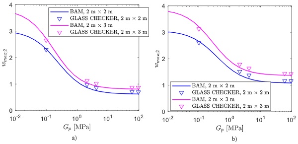
It may be noticed that there is a very good agreement between analytical and numerical results. Indeed, for the considered geometries and loads, the influence of the geometric nonlinearities isvery limited. However, when the monolithic limit is attained, the Glass Checker tends to overestimate the deflection with respect to the BAM approach. This is probably because, in this case (stiffer panes), the gas compressibility plays a relevant role and the Glass Checker, considering incompressible gas, tends to slightly overestimate the pressure variation arising in the cavity.
5. Conclusions
The recently proposed BAM (Betti's Analytical Method) approach for the calculation of DGUs, derived from classical theorems in linear elasticity, has been revised, presenting compact formulas for the relevant coefficients. Paradigmatic cases have been analyzed, comparing the results obtained with the BAM method with the numerical simulations performed with the Glass Checker by Maffeis Engineering, which is part of an integrated parametric approach to the design of façades. The Glass Checker, based upon an iterative numerical procedure, provides a precise calculation for any kind of build-up, panel shapes and load condition, automatically updating the result when the geometry and/or the boundary conditions change.
When the effects of the geometric nonlinearities plays an important role (large and thin plates), the BAM approach, despite being based on linear elasticity theory, still allows to capture, with very good accuracy, the pressure variation in the cavity and, consequently, the load sharing in the DGU. In order to evaluate the state of stress and deflection of the constituent panes, we suggest to use a posteriori a standard geometric-non-linear FEM analysis, with the pressure variation obtained with the BAM as input datum. Our study confirms that there is a good agreement between the results obtained with this procedure and the numerical results from other iterative methods, for DGU of various size and aspect ratio, under either uniform, line distributed or concentrated external loads.
When the DGU is made of laminated glass panes, their flexural stiffness may be readily estimated with the Enhanced Effective Thickness approach, allowing to correctly capture the response of plate geometries. Comparisons with numerical experiments for both square and rectangular plates, under either line-distributed and concentrated load, demonstrate that there is a good accuracy when the DGU is composed either by two laminated panes, or by a laminated pane and a monolith.
6. References
ABAQUS Analysis users manual, version 6.12. Simulia (2012)
ASTM E-1300-16: Standard practice for determining load resistance of glass in buildings. Standard, American Society for Testing Materials (2016)
prEN 16612: Glass in building - Determination of the lateral load resistance of glass panes by calculation. Standard, CEN/TC 129 (2016)
Feldmeier, F.: Zur Berücksichtigung der Klimabelastung bei der Bemessung von Isolierglas bei Überkopfverglasungen. Der Stahlbau8, 285-290 (1996)
Galuppi, L. and Royer-Carfagni, G. The effective thickness of laminated glass plates, J. Mech.Mater.Struct.7, 375-400 (2012)
Galuppi, L., Manara, G. and Royer-Carfagni, G., Practical Expression for the design of laminated glass, Composites Part B45, 1677-1688 (2013)
Galuppi, L., Manara, G. and Royer-Carfagni, G., Erratum and addendum to practical expressions for the design of laminated glass. Composites, Part B56,599–601 (2014)
Galuppi, L. and Royer-Carfagni, G. Betti's Analytical Method for the load sharing in double glazed units, Composite Structures,235, 111765 (2019)
Galuppi, L., Practical expressions for the design of DGUs. The BAM approach, Eng.Struct., submitted (2020)