This paper was first presented at GPD 2025.
Link to the full GPD 2025 conference book: GPD_2025_ConferenceProceedingsBook.pdf

Authors:
- Jakob Grötzner a
- Prof. Dr. Christian Schuler a
- Prof. Dr. Stefan Kolling b
- Paul Müller a
a. University of Applied Science Munich, Institute for Material and Building Research, Karlstraße 6, 80333 Munich, Germany, jakob.groetzner@hm.edu, christian.schuler@hm.edu
b. University of Applied Sciences Mittelhessen, Institute of Mechanics and Materials Research, Wiesenstraße 14, 35390 Gießen, Germany, stefan.kolling@me.thm.de
Abstract
The architectural trend towards transparent structures has resulted in a notable increase in the utilisation of glass in construction. In order to address the inherent brittleness of glass, laminated safety glass (LSG) is employed to meet the requisite safety standards regarding breakage, post-breakage, and residual strength. LSG is composed of at least two glass panes laminated into a monolithic composite with a polymer interlayer. This interlayer binds any glass fragments in the event of breakage and provides residual strength to the glazing. The bond between the glass panes and interlayer is crucial regarding the safety of the laminated glass. An increasing number of cases are reporting delamination effects between interlayers and glass panes. The most common damage patterns observed include discolouration, the formation of bubbles between panes or within the interlayer, and the formation of air channels, either described as snowflake-like constellations or similar channels originating from the edge, a process often referred to as viscous fingering. In the production process, clamps are often employed to apply pressure to the edges of the laminate in order to ensure optimal edge bonding. However, this can result in the generation of stresses within the LSG, particularly within the interlayer. In an initial study, researchers have analysed the influence of different clamp types, load levels and temperatures on the edge of LSG specimen, monitoring the thickness before, during and after the exposure. These insights represent an important step towards understanding the internal stresses caused by forces applied on the LSG element during the lamination process. The future objective is to ascertain whether these stresses, when subjected to environmental influences, may potentially contribute to delamination in installed glass elements. The findings of this research project are anticipated to provide insights into optimising lamination processes for enhanced durability and safety in architectural applications.
Article Information
- Published by Glass Performance Days, on behalf of the author(s)
- Published as part of the Glass Performance Days Conference Proceedings, June 2025
- Editors: Jan Belis, Christian Louter & Marko Mökkönen
- This work is licensed under a Creative Commons Attribution 4.0 International (CC BY 4.0) license.
- Copyright © 2025 with the author(s)
1. Introduction
1.1. Motivation and problem statement
Laminated safety glass (LSG) is a key material in modern architecture and engineering, valued for its safety, durability, and design versatility. It prevents shattering upon impact, enhancing security in both buildings and vehicles. Its adaptable nature enables innovative structural applications, while also providing additional benefits such as sound insulation, UV protection, and improved energy efficiency. These qualities make LSG an essential element in contemporary construction and design.
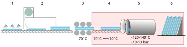
LSG consists of at least two layers of glass bonded together using a polymeric interlayer, which ensures the load-bearing and residual strength of the entire element. During the manufacturing process of new LSG elements (see Figure 1), the glass sheets are first thoroughly cleaned (1) and inspected for optical defects. Next, the glass is transferred to a cleanroom (2), where the interlayer is initially placed and checked for defects, contaminants, or inclusions before the next pane, which has also been cleaned and inspected in advance, is positioned on top of the element. This process is repeated until the entire LSG element is fully layered.
During the pre-bonding stage (4), remaining air is first pressed out of the LSG element using rolls at 30–40°C, followed by an increase in temperature to approximately 70°C to create a uniform bond by pressing the element together using rolls. To prevent delamination at the edges between the prebonding and the autoclave process, some manufacturers use clamps, which help minimize air inclusions during the final lamination step in the autoclave process (5). In some cases, manufacturers leave these clamps in place even during the autoclaving stage to completely eliminate the risk of edge separation. After the autoclave process, the laminated glass sheets are stored (6) and sometimes secured with clamps on racks awaiting further processing.
Delamination has long been recognized as a critical issue in LSG. It can be initiated by environmental factors such as moisture, temperature variations and ultraviolet (UV) radiation (Ensslen 2005, Kothe 2013). However, manufacturing-related factors can contribute to or cause delamination as well. These include among other things the inadequate cleaning of glass surfaces, geometric distortions in the glass elements, improper storage of the interlayer, elevated moisture levels during processing of the interlayer, irregularities during the pre-lamination process, and incorrect process parameters during the autoclaving cycle (Kuraray 2024).
The use of clamps during the manufacturing process may influence the final LSG element, particularly if their application results in permanent deformations within the assembly. Such deformations can lead to sustained internal stresses, similar to those caused by flatness deviations of individual glass panes, as described by Müller et al. (2024).
1.2. State of the art
Various test methods are currently available for assessing the mechanical adhesion of laminated glass, including the Pummel test (TROSIFOL 2012, Schuster et al, 2020), compression shear test (Jagota et al, 2000, TROSIFOL 2012), torsion test (TROSIFOL 2012), peel test, shear test, VW pull test, throughcrack tensile test (TCT) (Franz 2015), as well as impact tests such as the pendulum impact test or ball drop test. These quality assurance tests are only partially combined with artificial aging procedures. The structural performance of laminated safety glass (LSG) with PVB interlayers has been examined in relation to artificial weathering effects, including UV exposure, high temperatures, high humidity, and cyclic continuous loading (Schuler 2003, Schuler et al, 2004, Ensslen 2005, Sackmann 2008). The impact of artificial aging on different interlayers has been studied with regard to elevated temperatures, exposure to various climatic conditions, corrosion, and irradiation (Kothe 2013).
Further research has focused on simulating the behaviour of laminated glass in both intact and fractured states (Drass et al, 2018, Schuster et al, 2018, Brokmann et al, 2019, Brokmann et al, 2021, Müller-Braun et al, 2021, Pauli et al, 2021). The influence of artificial aging, including thermal cycling, high temperatures, and humidity, on interlayer materials has been investigated separately (Centelles et al, 2020). Additionally, studies have examined the creep behaviour of interlayers under continuous shear stress and high temperatures (Schimmelpenningh 2019), as well as the delamination behaviour of LSG (Butchart and Mauro 2012, Chen et al, 2021, Chen et al, 2022) and an experimental study on the time-dependent delamination behaviour of laminated safety glass (Müller et al, 2024)
None of these studies, however, address the question of to what extent the use of clamps in the manufacturing process may affect the final product.
1.3. Scope and outline
This study examines the influence of local clamping preassure during the manufacturing process of flat glass laminates as LSG with a PVB interlayer. Therefore, different clamping pressures are investigated. Their effect on the pre-bonded stage as well as the subsequent autoclave process and the storage afterwards are analyzed. The corresponding production steps are highlighted in red in Figure 1.
Research Questions Addressed in This Study:
- Do clamps influence the thickness of LSG packages during the manufacturing process?
- How does temperature influence the behaviour of the LSG unit in the clamping area?
- How does the element behave after the clamp is removed following the manufacturing process (springback behaviour, delamination effects)?
2. Testprogram
2.1. Test concept
To address the research questions raised in the previous chapter, the following conditioning matrix was developed:
Table 1: Temperatures and holding times of the test series.
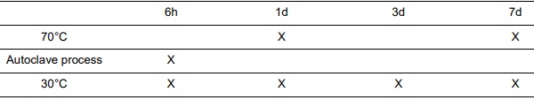
The experiments, which are described in detail in section 2.4, generally included the following:
- Initial measurement of the thickness of the specimen at all measuring and reference points
- Application of force using clamps on position 3 at every measuring point
- Conditioning of the specimen according to Table 1 and monitoring of the change in clamping force for the test series at 30°C and 70°C
- Measurement of the thickness of the specimen at all measuring and reference points 1h after conditioning
- Periodical measuring of the thickness of the specimen at all measuring and reference points over the course of one week
2.2. Specimen
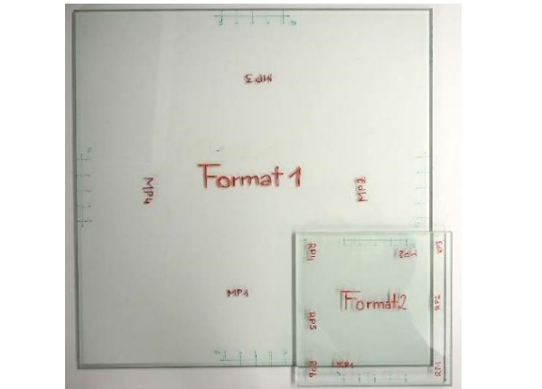
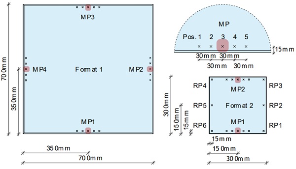
The glass panes used were LSG elements with a composition of 2 × 6mm float glass (FG) + 1.52mm PVB B200NR, in two different formats (see Figure 2 and Figure 3).
- Specimen Format 1 VSG 700 x 700mm² (2 x 6mm FG + 1.52mm interlayer)
- Specimen Format 2 VSG 300 x 300mm² (2 x 6mm FG + 1.52mm interlayer)
2.3. Methodical Monitoring of the tests
Monitoring of the Clamping Force
As part of the various test series, two different clamps from the manufacturer "Bessey" were used:
- Type 1 - Model „DuoKlamp “, Clamping Surface: Bottom = Top = 992mm²
- Type 2 - Model „classiX GS 20”, Clamping Surface: Bottom = 804mm² Top = 934mm²
To precisely adjust the load levels, the clamps were equipped with strain gauges of the manufacturer “Tokyo Measuring Instruments Lab”. For this purpose, positions with consistent bending stress were selected. In the case of clamp Type 2, these positions were ground level before applying the strain gauges.
Before each test, the strain gauges on the clamps were calibrated using an S9M/5kN force sensor from the manufacturer “HBM”. For this procedure, each clamp was first zeroed in a stress-free state and then tightened to the corresponding target strain level, which was determined using the force sensor. The associated strain value was then recorded. After calibration, the clamps could be re-tightened on the specimen to the desired strain level, ensuring the correct force application.
During the autoclave tests, the clamps had to be disconnected. To determine the residual load on the glass panes, the clamps were reconnected, and the strain values of the strain gauges were recorded. Subsequently, the clamps were released, and the force sensor was used to determine the corresponding load values for the recorded strain measurements.
For the 70°C tests, force sensors of the type S9M/5kN were directly clamped onto the glass panes. This approach was chosen to eliminate distortions caused by the heating of strain gauge cables. Force sensors used in these tests are designed by the manufacturer to withstand temperatures up to 120°C.
Measuring of the Thickness of the Specimen
For measuring the thickness of the specimens before and after the tests, a micrometre screw gauge from the manufacturer “Mitutoyo” was used. The measurement instrument has an accuracy of 1 µm.
Initial measurements of all specimens were taken after storage at room temperature for the period of 1d at all five positions (Pos.) of the measurement points (MP) (see Chapter 2.2), as well as at the reference points (RP). All measured locations were marked on the specimens with permanent markers prior to the first measurement as visible in Figure 2 to ensure that measurements were taken always at the same locations. Thickness values used for evaluation represents an average of multiple individual measurements.
Following the tests and the removal of the clamps, the specimens were subjected to repeated measurements over the course of one week to assess whether the LSG units exhibited any changes under the residual stresses when stored at room temperature.
2.4. Configurations
Test Series – 70°C & 50% rel. Humidity
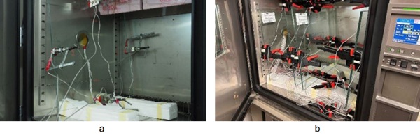
The 70°C tests were conducted in a climate chamber from the manufacturer “Espec”, with the humidity level set to 50%. Due to the elevated temperature, Type 2 clamps were used in these tests. The force signal in this test series was recorded using S9M/5kN force sensors, rather than strain gauges as shown in Figure 5a, as previously described in Chapter 2.3. Only specimens of Format 1 were used in this test series.
The specimens were placed upright in the climate chamber on spacers to ensure clearance from the chamber floor as well as the walls, allowing for the installation of the clamps and preventing any contact between the glass elements and the metal lining of the chamber. Subsequently, the load cells were clamped onto the specimens and tightened to the respective load levels. Prior to activating the climate chamber, measurement points 1 and 3 were loaded to a level of 1.1 kN, while the remaining measurement points 2 and 4 were subjected to a load of 500 N.
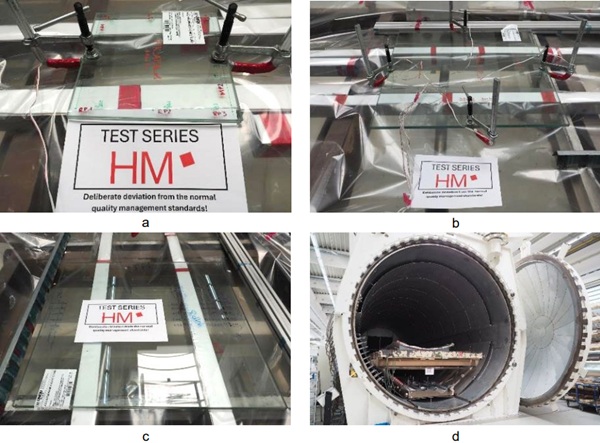
Test Series – Autoclave (140°C – 10bar)
To accurately capture the influence of clamps during the autoclave process and precisely analyse the resulting effects, two different glass formats (see Chapter 2.2) were subjected to an autoclave process under varying load levels and preconditioning conditions. The glass panes were horizontally stored (as shown in Figure 4a–c) and transferred into the autoclave (Figure 4d), where they underwent a full processing cycle with a maximum temperature of 140°C and a maximum atmospheric pressure of 10bar. Due to the high temperatures, clamps of Type 2 had to be used. The load levels were set at 1100N and 500N.
One glass pane of Format 1 was subjected to 1100N at measurement points MP1 and MP3 and with 500N at measurement points MP2 and MP4. For the Format 2 panes, both measurement points MP1 and MP2 were loaded at the same force level. One pane was subjected to 1100N, while the other was loaded with 500N. The second Format 1 specimen underwent the Autoclave cycle without clamps (Figure 4c). The pane was preconditioned at 120°C whilst subjected to three load levels (1000 N, 800 N, and 600 N), resulting in corresponding deformations. The objective was to examine how these deformations developed during the autoclave process.
Test Series – 30°C & 50% rel. Humidity
In the test series conducted at 30°C, Type 1 clamps were used (see Figure 5b), and these test series were as the series at 70°C also conducted in a climate chamber from the manufacturer “Espec”. While clamps Type 1 offer less precise adjustability compared to Type 2 clamps due to their design, they are commonly used within this temperature range and were chosen for that reason. Only specimens of Format 1 were used in these tests.
As previously described in the tests at 70 °C, the specimens were placed on spacers to allow for clamp installation while maintaining a gap between the glass and the chamber floor. Prior to activating the climate chamber, the clamps were tightened to the respective load levels using their strain gauge measurements (MP1 and MP3 to 1.1 kN; MP2 and MP4 to 500 N).
3. Results
3.1. Clamping force over the duration of various test scenarios
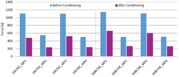
In the following bar charts, the calculated and measured load levels of the various specimens at the time of clamp installation are compared with the residual force levels after the conditioning process. The individual specimens are separated by vertical dashed lines. As already explained in Chapter 2.3 the series at 70°C uses S9M/5kN force sensor whilst the Autoclave series as well as the series at 30°C uses the strain gauge measurements of the clamps to determine the force values.
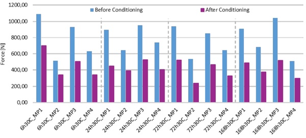
In the test series at 70 °C and 30 °C, the labels of specimen start with the duration of exposure, followed by the exposure temperature, and concludes with the corresponding measurement point presented in the results.
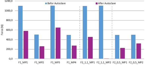
In the autoclave experiments, the specimens were labelled according to their geometries, as the exposure duration remained constant throughout this test series. 'F1' refers to specimen format 1, while 'F2' denotes format 2. For specimens of format 2, the designation was further extended to include the applied load level (1.1 kN or 0.5 kN). Finally, each label includes the respective measurement point of the element.
At 70°C the loss in in force is up to 58,0% and on average 50,1%. During the autoclave process, the clamping forces decreased by up to 58.9% with an average reduction of 47.7% and were converted into deformation. No post-autoclave value is available for F2_1.1_MP2, as the strain gauge sensor did not withstand the test. The 30 °C series showed a loss of up to 55.1%, with an average reduction of 44.7%. Beyond a loading duration of 24 hours, no clear influence of exposure time could be observed.
Test Series – 70°C & 50% rel. Humidity
Test Series – Autoclave
Test Series – 30°C & 50% rel. Humidity
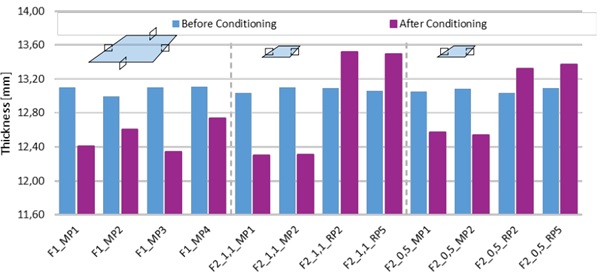
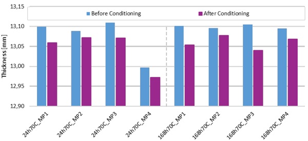
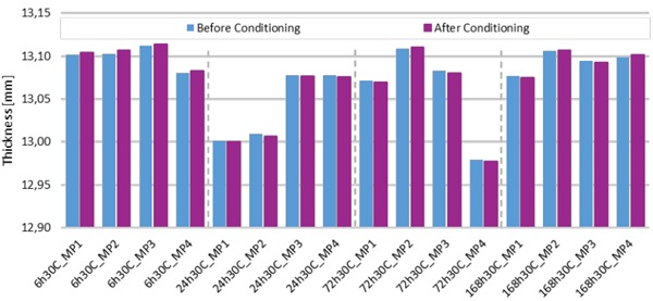
3.2. Comparison of the initially measured LSG element thickness with the thickness after conditioning
The following diagrams illustrate the thickness changes of individual LSG elements caused by their respective conditioning processes.
The shown measurement values were exclusively recorded at Position 3 of each respective measurement point, as well as the reference points RP 2 and 5 of the Format 2 specimens (only autoclave test series), as these locations exhibited the greatest changes. The individual specimens are separated by vertical dashed lines.
At 70 °C, clamps already cause permanent deformations in the interlayer at a load of 500 N (the lower of the two investigated load levels), leading to stresses in the LSG element. Depending on the applied load, minor extrusions may also occur. In this temperature range, deformations at the loaded positions (Position 3) of the measurement points (see Chapter 2.2) ranged from 0.016 mm at a load level of 500 N to 0.065 mm at a load level of 1.1 kN.
It should be noted, however, that the changes in thickness caused by the clamping load are smaller than the variation in thickness measurements observed within some LSG elements.
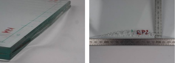
The changes in thickness intensify during the autoclave process to the extent that delamination phenomena were observed in specimens Format 2 at locations without clamps (see Figure 12). RP 2 and 5 of the F2_ specimen in Figure 9 show the lifting effect on the sides without clamps by an increase in element thickness. The extrusions were also substantial, as shown in the aforementioned figure, and thickness variations ranged from 0.37 mm at 500 N (Specimen Format 1) to 0.79 mm at 1.1kN (Specimen Format 2).
The test series at 30 °C, shown in Figure 11, does not indicate a clear development of clamp-induced deformations and the thickness variations between individual measurement points significantly outweigh any potential deformation effects.
Test Series – Autoclave
Test Series – 70°C & 50% rel. Humidity
Test Series – 30°C & 50% rel. Humidity
3.3. In-Plane Deformations of the Interlayer Based on Specimens F2_1.1 & F2_0.5
The change in interlayer thickness during the autoclave process also resulted in in-plane deformations of the interlayer as can be seen in Figure 12. Specifically, extrusions occurred at measurement points 1 and 2, the points where the clamps were attached while delamination effects were observed at reference points RP2 and RP5 which had no clamps during the autoclave cycle, as illustrated in the following figure. These effects were visible at both load levels.
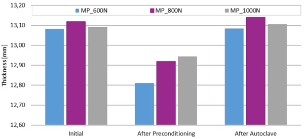
3.4. Results of the Preconditioned Specimen After the Autoclave Process
The following bar chart presents the thickness measurements of the preconditioned element that underwent the autoclave cycle without the use of clamps.
It can be observed that the measured values after the autoclave process have returned to values close to their initial values. Additionally, the previously recorded in-plane deformations of the interlayer caused by preconditioning were fully reversed.
3.5. Results of the Monitoring After the Tests
The panes were stored at room temperature over the course of one week, during which measurements were repeated continuously. However, no clear change in deformation was observed—neither at the measurement points nor at the reference points.
4. Conclusions
To evaluate the influence of clamping pressure on LSG units during the production of flat glass laminates, specimens were subjected to two different load levels (500 N and 1100 N) and exposed to 30 °C and 70 °C as well as a full autoclave cycle with temperatures up to 140°C. This study is limited to uniaxial clamping forces in conventional flat glass lamination. The findings should not be generalized to special lamination processes where other or additional forces may be involved.
As shown in the test series at 70 °C, the use of clamps at elevated temperatures has a measurable impact on the thickness and, consequently, on the multiaxial stress state of the laminate. Therefore, the use of clamps under such thermal conditions is not recommended.
These effects were amplified during the autoclave tests. Deformations were observed, which may lead to permanent stresses in the final installation configuration and could potentially contribute to delamination behaviour at a later stage. For this reason, the use of clamps during the autoclave process is strongly discouraged.
However, the results of this study also suggest that the use of clamps during the manufacturing process is unproblematic, provided that the glass elements have fully cooled (i.e., do not exceed 30 °C) and that the unit is not exposed to heat while the clamps are in place. This conclusion assumes that multiple clamps are not applied in close proximity—since such configurations were not examined in this study— and that the force exerted by each individual clamp does not exceed 1.1 kN.
Accordingly, the use of clamps during the assembly of facade systems under the aforementioned boundary conditions (i.e., temperatures ≤ 30 °C and clamp forces < 1.1 kN) can also be considered uncritical.
Based on these findings, new questions arise regarding the impact of the measured thickness changes on the load-bearing capacity of LSG elements. Furthermore, defining a temperature threshold at which clamp application becomes critical may prove beneficial.
Acknowledgements
This study is part of the research project Delamination, funded by the German Federal Ministry of Education and Research (BMBF). We gratefully acknowledge the support of our project partners, particularly sedak, for their technical assistance and for providing access to their autoclave for testing.
References
Brokmann, C., Alter, C., Kolling, S. Experimental determination of failure strength in automotive windscreens using acoustic emission and fractography Glass Struct Eng 4(2), 229–241 (2019). http://doi.org/10.1007/s40940-018-0090-9
Brokmann, C., Kolling, S., Schneider, J. Subcritical crack growth parameters in glass as a function of environmental conditions Glass Struct Eng 6(1), 89–101 (2021). http://doi.org/10.1007/s40940-020-00134-6
Butchart, C., Mauro, O. Delamination in fractured laminated glass. In: Proc. 3rd Int. Conf. Eng. Transpar., Düsseldorf, Germany (2012)
Centelles, X., Martín, M., Solé, A., Castro, J.R., Cabeza, L.F. Tensile test on interlayer materials for laminated glass under diverse ageing conditions and strain rates Construction and Building Materials 243, 118230 (2020). http://doi.org/10.1016/j.conbuildmat.2020.118230
Chen, X., Rosendahl, P.L., Chen, S., Schneider, J. On the delamination of polyvinyl butyral laminated glass: Identification of fracture properties from numerical modelling Construction and Building Materials 306, 124827 (2021). http://doi.org/10.1016/j.conbuildmat.2021.124827
Chen, S., Chen, Z., Chen, X., Schneider, J. Evaluation of the delamination performance of polyvinyl-butyral laminated glass by through-cracked tensile tests Construction and Building Materials 341, 127914 (2022). http://doi.org/10.1016/j.conbuildmat.2022.127914
Drass, M., Schneider, J., Kolling, S. Damage effects of adhesives in modern glass façades: a micro-mechanically motivated volumetric damage model for poro-hyperelastic materials International Journal of Mechanics and Materials in Design 14(4), 591–616 (2018). http://doi.org/10.1007/s10999-017-9392-3
Ensslen, F. Zum Tragverhalten von Verbund-Sicherheitsglas unter Berücksichtigung der Alterung der Polyvinylbutyral-Folie. Dissertation, Ruhr-Universität Bochum (2005)
Franz, J. Untersuchungen zur Resttragfähigkeit von gebrochenen Verglasungen: Investigation of the residual load-bearing behaviour of fractured glazing, 1st edn. Springer Berlin Heidelberg; Imprint: Springer Vieweg, Berlin, Heidelberg (2015)
Jagota, A., Bennison, S.J., Smith, C.A. Analysis of a compressive shear test for adhesion between elastomeric polymers and rigid substrates International Journal of Fracture 104(2), 105–130 (2000). http://doi.org/10.1023/A:1007617102311
Kothe, M. Alterungsverhalten von polymeren Zwischenschichtmaterialien im Bauwesen. Dissertation, Technische Universität Dresden (2013)
Kuraray, Technical Manual Architecture, 2nd edition, Publisher Kuraray Europe GmbH (2024)
Müller, A., Schuler, C., Grötzner, J., Dix, S., Hiss, S. (2024). Imperfections in laminated safety glass - an experimental case study. Challenging Glass Conference Proceedings – Volume 9 – June 2024
Müller-Braun, S., Brokmann, C., Schneider, J., Kolling, S. Strength of the individual glasses of curved, annealed and laminated glass used in automotive windscreens Engineering Failure Analysis 123, 105281 (2021). http://doi.org/10.1016/j.engfailanal.2021.105281
Pauli, A., Kraus, M.A., Siebert, G. Experimental and numerical investigations on glass fragments: shear-frame testing and calibration of Mohr–Coulomb plasticity model Glass Struct Eng (2021). http://doi.org/10.1007/s40940-020-00143-5
Rasmussen, S. C. (2025). Art and Inspiration: Edouard Benedictus and the Invention of Laminated Safety Glass. ChemPlusChem, 90(1), e202400572.
Sackmann, V. Untersuchungen zur Dauerhaftigkeit des Schubverbunds in Verbundsicherheitsglas mit unterschiedlichen Folien aus Polyvinylbutyral, Technische Universität München (2008)
Schimmelpenningh, J. Laminated Glass: Creep of Unsupported Glass Pane. In: Glass Performance Days 2019. Glass Performance Days, Tempere, Finland, 26. - 28.06.2019 (2019)
Schuler, C. Einfluß des Materialverhaltens von Polyvinylbutyral auf das Tragverhalten von Verbundsicherheitsglas in Abhängigkeit von Temperatur und Belastung. Dissertation, Technische Universität München (2003)
Schuler, C., Bucak, Ö., Albrecht, G., Sackmann, V., Gräf, H. Time and Temperature Dependent Mechanical Behaviour and Durability of Laminated Safety Glass Structural Engineering International 14(2), 80–83 (2004). http://doi.org/10.2749/101686604777964026
Schuster, M., Kraus, M., Schneider, J., Siebert, G. Investigations on the thermorheologically complex material behaviour of the laminated safety glass interlayer ethylene-vinyl-acetate Glass Struct Eng 3(2), 373–388 (2018). http://doi.org/10.1007/s40940-018-0074-9
Schuster, M., Schneider, J., Nguyen, T. an. Investigations on the execution and evaluation of the Pummel test for polyvinyl butyral based interlayers Glass Struct Eng 5(3), 371–396 (2020). http://doi.org/10.1007/s40940-020-00120-y
TROSIFOL. TROSIFOL Manual (2012)