Source: Glass Structures & Engineering
Authors: Isabell Ayvaz, Timon Peters, Thiemo Fildhuth, Gergana Rusenova, Anna Buksak, Matthias Haller, Miriam Schuster, Ulrich Knaack & Michael Kraus
DOI: https://doi.org/10.1007/s40940-025-00312-4
Abstract
Glass in facades and roofs is usually used as infill elements to provide daylight supply in buildings. The load is typically transferred via a substructure. This leads to resource-intensive constructions, whereby usually the static potential of the glass panes is not taken into account. In a research project, this missing efficiency was investigated, resulting in a linear metal edge fitting that enables load-bearing glass structures by transferring tensile and compressive forces as well as bending moments. The fittings are laminated into safety glass while the use of Insulated Glazing Units (IGU’s) provides thermal performance. Since insulating glass is typically not used as a primary load-bearing structure, the entire process chain had to be redesigned and developed, from 3D planning and form-finding to design and structural analysis, manufacturing, testing and assembly. The paper focuses on the structural performance of the developed fitting. Analytical models were used to approximate the rotational stiffness of the fitting, followed by parameter studies to understand the influence of key geometric and material variables. This revealed the importance of flange thickness on the overall rotational stiffness of the linear fitting. A full-scale mockup (approximately 7 m × 3 m) was assembled to assess buildability under real-world conditions, revealing both the practical viability and current limitations of the system. Mechanical testing on specimen with fitting dimensions used in the mockup led to a bending stiffness of 6 kNm. Among the identified challenges are the precision of the lamination process, control of welded seam quality, and long-term performance under environmental influences. Additionally, aspects related to thermal performance/building physics requirements and durability require further investigation before the system can be considered for broader application.
1 Introduction
1.1 Background
Shell structures are known for their exceptional structural efficiency, as their curved geometry enables an effective distribution of forces, primarily through membrane action. While traditional shell constructions rely on materials like reinforced concrete (Block 2017), timber (e.g., Multihalle in Mannheim, Germany), or steel, transparent shell structures offer additional benefits: they combine structural function with daylight supply and aesthetical appeal. Most commonly, however, glass panes are predominantly used as non-structural infill elements. The transfer of loads is typically assigned to a secondary supporting substructure. This approach often results in material-intensive systems that fail to exploit the structural potential of glass as a load-bearing element. In the last decades, glass has increasingly been recognized not only for its transparency but also for its high compressive strength, making it a suitable load-bearing material in shell structures that are optimized for membrane forces (Baldini 2005). However, due to its brittle failure behavior, structural use of glass remains highly dependent on the reliability of its connectors. Ensuring sufficient load transfer, redundancy, and post-failure capacity at the joints remain key challenges in the design of transparent shells (Fildhuth 2012).
1.2 State of the art: laminated metal–glass connectors
In structural glass construction, three fundamental connection principles are typically distinguished: form-closed (mechanical interlocking), force-closed (friction-based), and material-closed (adhesive-bonded) joints. While bolted or clamped point fixings are widely used due to their simple installation, they often introduce local stress concentrations, which are critical for brittle materials like glass. Adhesive bonding, on the other hand, offers continuous load transfer and a more uniform stress distribution, but it requires precise surface preparation, controlled curing conditions, and long-term environmental resistance (Schuster et al. 2021; Stevels et al. 2020).
In recent years, embedded inserts laminated with the help of interlayers have gained increasing attention. These systems combine the advantages of adhesive bonding and mechanical interlocking, allowing inserts to be factory-laminated into the interlayer of glass units. The hybrid nature of these connections enables precise prefabrication and allows for simple on-site assembly using mechanical fasteners like bolts (e.g., Fildhuth et al. 2022) or rivets (e.g., Marinitsch 2015). Moreover, they avoid the need to drill through the glass and enable the disassembly or replacement of components—something not feasible with purely adhesive-bonded joints.
The geometric complexity of laminated inserts ranges from flat inserts (Louter et al. 2019), over U- (Hagl 2008) and T-shaped profiles (Fildhuth 2022) to highly integrated custom geometries e.g. embedded in cutouts (Martens 2016) or both interlayers of triple-glazed units (Marinitsch 2015). Material selection also plays a critical role: While O’Callaghan (2012) demonstrated the application of titaniumFootnote1 inserts, most practical applications use stainless steel for its balance of ductility, strength, and cost-efficiency. The ductility of the metal compensates for the brittleness of the glass and contributes to controlled failure behavior (Fildhuth et al. 2022).
Despite their structural benefits, lamination of inserts remains challenging. Studies by Carvalho (2010) and Puller (2012) emphasize that uneven insert geometries can lead to bubble formation in the interlayer due to incomplete contact during autoclaving. Additional fixtures or lamination strategies are often needed to hold the insert in position during the process (Carvalho et al. 2010; Marinitsch 2015) and ventilation possibilities during lamination need to be taken into account to avoid bubble formation. Achieving precise positioning is crucial for meeting assembly tolerances and ensuring effective load transfer. Also, the surface quality of the metal insert play a significant role in the reliability of the hybrid system.
Research on laminated glass-metal connectors is extensive. Bagger (2010), Martens (2016), and Bedon and Louter (2014) explored concepts based on continuous embedded metal plates within triple-laminated glass. Hagl (2002, 2008) studied U-shaped bonded metal connectors using silicone, revealing how geometric confinement influences stiffness and stress distribution in the adhesive. Her findings show that increasing geometric complexity of the adhesive bond as well as reducing adhesive thickness can significantly increase connection stiffness (Hagl 2008). Silvestru (2018) tested silicone and acrylate adhesives for surface and edge bonding, showing how bond configuration (flat, L- or U-shaped) impacts load capacity and failure behavior. Puller (2012) examined ionomer interlayers and optimized insert shapes through numerical and experimental methods to improve load distribution and reduce stress peaks. Volakos et al. (2020) investigated inserts embedded in resin, exploring the potential of castable transparent materials for bonding metal sheets in glass edges. Fildhuth et al. (2022) and Stevels et al. (2022). developed locally laminated T-shaped stainless-steel connectors,Footnote2 offering ductile behavior and tolerance compensation via oversized holes filled with injection mortar. However, the bending stiffness of this local solution remained limited. Marinitsch (2015) proposed a continuously laminated, riveted edge connection with improved stiffness, but high fabrication complexity and scalability limitations arise due to the required density of mechanical fasteners and the triple-laminated configuration.
Beyond structural performance, several studies have also addressed installation constraints and practical implementation. For example, Carvalho et al. (2010), and Trometer and Kruppna (2006) discussed deviations during lamination due to metal insert geometry and proposed both rigid and hinged concepts. Full-scale demonstrators—such as the “Gravity” project presented at Glasstec 2018 (Messe Düsselforf GmbH (ed.) 2018)—have shown the feasibility of carrying large loads (e.g., a 1.5-ton vehicle) through thin glass panels bonded to metal hangers using silicone, highlighting the potential of structural adhesives.
1.3 Aim of the study
The primary objective of the present work is the development of a linearFootnote3 connection detail suitable for both horizontal and vertical frameless glass shell structures, enabling the structural activation of the glass elements themselves. Existing solutions (compare Sect. 2) have demonstrated the feasibility of embedded fittings in laminated glass. However, according to the authors’ knowledge, there is currently no fitting solution that combines effective bending stiffness, structural redundancy, ease of fabrication, and architectural clarity in a scalable and cost-efficient form.
The work is part of the research project ‘anonymous’. By harnessing the load-bearing capacity of the glass, the project aimed to facilitate material-efficient transparent shell structures while simultaneously maintaining the performance of a thermally insulating building envelope. To achieve this, the laminated linear fitting is intended for use in insulating glass units (IGUs). This ambition necessitated a comprehensive redefinition of the design and implementation process, encompassing all phases from form-finding and digital planning, to structural design, manufacturing, assembly, and repair. The work resulted in the development of a continuously laminated metal insert (in the following referred to as ‘linear fitting’). This paper presents an excerpt of the development, analysis, and testing of the novel continuously laminated metal fitting and focuses on the structural and construction related challenges.
Section 2 of the paper outlines the geometric, structural and buildability-related requirements and presents the evolution of the fitting development. Section 3 presents the concept of a mockup which was realized, addressing form-finding and the structural design. In Sect. 4, the joint stiffness is investigated. This includes theoretical models to determine the stiffness of the connection (Sect. 4.1), parameter studies on the influence of the geometry of the fitting on its stiffness (Sect. 4.2) and results on bending tests performed on the fitting. Section 5 presents manufacturing- and installation-related challenges throughout the realization of the mockup. In Sect. 6, an outlook on the need for further investigation is provided.
2 Development of the fitting geometry
2.1 Requirements
The requirements for the fitting are directly derived from the functional and structural demands of a glass shell.Footnote4 These requirements can be categorized into aesthetic, geometric, structural, building physics and practical/ installation related considerations.
Aesthetic requirements: The connection must maintain a uniform and slender joint depth to ensure a seamless integration into the global shell structure. The fitting should not protrude from the surface of the glass elements, thereby creating a "flush joint" that preserves the seamless appearance and elegance of the shell.
Geometric constraints: A uniform visible joint width shall provide architectural elegance. In order to allow handling during the assembly and potential disassembly of the structure a sufficient joint width has to be taken into account.
Structural performance: The fitting must ensure effective load transfer between glass elements while maintaining redundancy and robustness. It should be capable of absorbing unexpected forces, including those arising from manufacturing tolerances, assembly imperfections, or dynamic load variations, including temperature differences.Footnote5 The glass setup has direct consequences for the structural performance. An increase in the number of adhesive interlayers results in a lower stiffness of the laminated glass, which must be carefully considered to avoid excessive deformation. Additionally, while a thicker glass section provides a larger lever arm for load transfer along the bonded edge, it also increases the overall weight of the structure. Consequently, the fitting must be capable of handling higher loads without compromising its efficiency.
Building physics performance: The joints between adjacent glass elements must be reliably sealed and allow insulating material to be incorporated to keep thermal bridges to a minimum. The integration of insulated glazing units is essential for achieving adequate thermal performance. While the detailed assessment of building physics lies beyond the scope of this paper, ongoing investigations—including simulation studies and climate chamber testing—are being conducted to evaluate the thermal behavior of the system.
Buildability and component exchange: The fitting must be designed to facilitate efficient installation and potential replacement, minimizing complexity during construction. The manufacturing process of the fitting itself and the lamination should be economically viable and material-efficient.
2.2 Evolution of existing solutions
The development of the novel fitting presented in this paper builds upon insights from previous research into laminated metal–glass connectors, particularly the dove-tailed fittings by Fildhuth et al. (2022) and the riveted connectors developed by Marinitsch (2015). Both solutions demonstrated specific advantages, but also exhibited limitations. Figure 1 provides an overview of the conceptual evolution. As insert type we distinguish ‘linear’ and ‘local’ laminated inserts. An insert is categorized as linear if it is laminated continuously along a glass edge (excluding potentially necessary thermal joints). Local inserts are limited in width ≤ 6 cm.
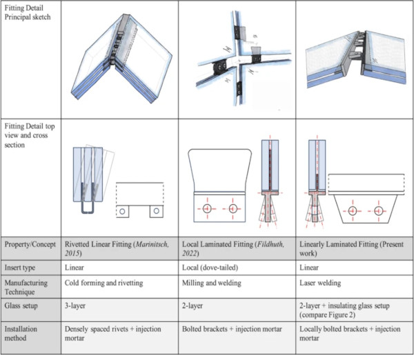
Figure 1 Left illustrates the linearly riveted fitting introduced by Marinitsch (2015), which uses a continuous metal profile connected by closely spaced mechanical rivets along the glass edge. This design achieves high bending stiffness through full-edge engagement, but is constrained by its high manufacturing complexity, the need for three-layer glass laminates, and the dense rivet spacing
Figure 1 Centre shows the local laminated fitting developed by Fildhuth et al. (2022), which integrates a T-shaped stainless-steel insert into the glass edge via structural PVB lamination. Load transfer is achieved via bolted brackets, and tolerance compensation is provided through oversized holes filled with injection mortar after the assembly. The connector showed excellent performance in transferring translational forces and demonstrated ductile failure behavior. In the connection proposed by Fildhuth et al. (2022) different angles in a shell are accounted for in the metal fitting only, while in the design proposed by Marinitsch, both the glass edge as well as the fitting are cut. This enables uniform visible joint widths independent of the variations in the shell geometry (compare \* MERGEFORMAT Fig. 1)
The linear fitting developed in this work (Fig. 1 Right) merges the architectural appeal and structural performance of a linear insert with the flexibility and simplicity of a locally bolted connection. Orienting on the design from Fildhuth, the fitting consists of a T-shaped stainless-steel profile, where the vertical web is embedded in the PVB interlayer along the glass edge, and the horizontal flange is laminated onto the exterior edge of the glass. This configuration enables both shear transfer through the interlayer and bending moment resistance via a force couple between the bonded flange at the glass edge, similar to the mechanism proposed by Fildhuth et al., but extended over the full edge length.
In addition, the fitting retains the mechanical connecting brackets from the local concept to allow precise assembly, take up tolerances, and allow plastification under loading (compare Sect. 4.3). As all the local brackets along an edge are fixed to the T-bar, bracket distance is highly controllable and dependency on the lamination process is minimized.Footnote6 The use of a linear insert also increases the potential for secondary load paths in case of partial failure of individual connectors, thereby improving system redundancy, which is a critical aspect in shell structures subjected to multidirectional load conditions.
As the goal of the project was to find a solution that allows for thermally insulated glass shells, the integration of insulated glass and sealing possibilities is accounted for. A sketch is shown in Fig. 2. Laminated safety glass is used as the load-bearing layer using heat-strengthened float glass. Even though being not as strong as fully tempered glass, heat-strengthened glass offers additional safety in the event of glass breakage when used as laminated safety glass, due to its coarser fracture pattern and hence residual load-bearing capacity, which is particularly essential for applications such as overhead glazing. Although annealed glass would also be permissible, heat-strengthened glass offers a higher thermal shock resistance, which reduces the risk of glass breakage in the event of extreme temperatures or thermal bridges that could evoke stress in the glass in the surrounding of the stainless-steel fitting. Structural PVB (compare Eastman Chemical Company, Saflex Datasheet (2020)) is used as an interlayer. The web of the T-bar was laminated, using 4 × 0.76 mm thin structural PVB sheets – two at the level of the web and one above and below the T-bar. At the glass edge the use of 2 × 0.76 mm was intended to balance stiffness and tolerance compensation.
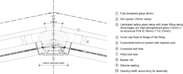
The glass setup is displayed in \* MERGEFORMAT Fig. 2. The load-bearing layer is supplemented by an insulating glass setup using fully tempered glass. Eight insulating glass units are connected with the developed linear fittings. The geometry was designed to provide uniform visible joint widths. The outer opening was set to at least 20 mm which were necessary for installation purposes.
The bolt head was specifically designed by the producer to compensate for installation tolerances. It features an extended diameter to cover the oversized borehole and includes a small central hole to allow post-assembly injection of mortar for mechanical fixation. Investigations and improvements to meet building physics requirements are part of ongoing research.
2.3 Manufacturing of the fitting
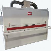
Several fabrication methods were evaluated to determine a suitable manufacturing approach for the fitting. Handheld laser welding was ultimately selected as the most suitable manufacturing method for the linearly laminated fitting. While not yet a standardized industrial process for structural components, this technique offers several decisive advantages: it allows for the flexible joining of components of arbitrary size, supports the realization of geometrically complex configurations without the need for extensive tooling, and can be readily adapted to varying production scales. These characteristics are particularly beneficial in prototypical or small-batch production scenarios. Nevertheless, the method does present certain challenges, notably in achieving uniform seam quality and reproducibility. However, given the experimental nature of the mock-up and the requirement for manual adaptability during assembly, these challenges were considered acceptable. The use of handheld laser welding also provides a promising foundation for future refinement—potentially via automation—to further improve production consistency and seam quality.
Alternative manufacturing methods were thoroughly examined but found less suitable for the specific demands of the fitting. Milling, which had previously proven effective for local inserts (Fildhuth et al. 2022), offers high dimensional accuracy and precision in complex geometries. However, its application to a linear, repetitive fitting was deemed inefficient due to excessive material waste and elevated production costs, both economically and ecologically.
Profile extrusion, a technique known for excellent geometric consistency and cost-efficiency in high-volume production, was excluded due to its inherent inflexibility regarding geometric variation. Given the highly differentiated nodal angles in the developed shell structure (compare Sect. 3, Fig. 3), extrusion would only be viable in future iterations should a standardized T-profile be developed for large-scale, repetitive applications.
Off-shelf steel profiles were also assessed. These, however, presented limitations in terms of dimensional flexibility. Profiles with flange widths of 20–25 mm and web depths of around 20 mm were only available with web thicknesses starting at 3 mm. This would require at least six layers of PVB (0,76 + 4 × 0,76 + 0,76 mm). This was not intended as it adds additional weight on the one hand and decreases stiffness of the glass laminate on the other hand. The intended design demands varying thicknesses for the flange, web, and bracket elements—an adaptation not feasible with standard profiles.
Cold-forming of sheet metal was explored as another option, offering economic and scalable production for specific geometries. Nonetheless, the process is constrained by its limited capacity to accommodate varying material thicknesses within a single component. The design intent of the fitting, which integrates zones of varying stiffness and load transfer, precluded the use of this method.
Conventional laser welding was initially considered promising, offering minimal distortion and high-precision joints widely used in advanced structural applications. However, it typically requires rigid automation setups and controlled environments with specialized clamping systems. These constraints are difficult to reconcile with the flexible, geometry-dependent nature of the fitting.
Additive manufacturing (e.g., 3D printing) was briefly explored but quickly dismissed due to limitations in scalability, production speed, and cost-efficiency for components of structural dimensions.
In summary, handheld laser welding represents a pragmatic balance between flexibility, precision, and adaptability—making it the most appropriate fabrication method for the current development stage of the linearly laminated fitting.
3 Concept of the mockup
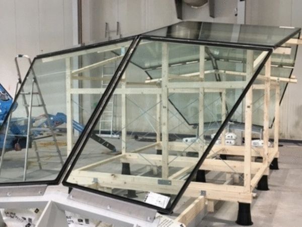
In order to investigate the scalability of the developed connection, a mockup was designed that was showcased on the Glasstec trade fair 2024 in Düsseldorf. The main intention was to determine manufacturing procedures (e.g., lamination techniques and parameters), test an automated planning workflow (from geometry generation over structural calculations to the generation of manufacturing related details like component labelling) and find a suitable assembly concept.
3.1 Geometry and glass setup
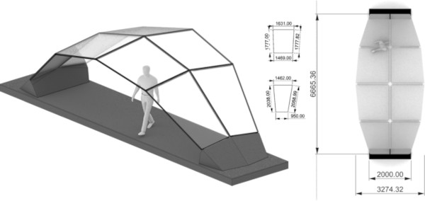
The geometry of the mockup was built as a segment of an elliptical shell structure. The global geometry is double-symmetric (compare \* MERGEFORMAT Fig. 3). Yet, this is not the case for the metal insert as they always form a pair of complementary elements (compare \* MERGEFORMAT Fig. 2). The geometry of the glass shell was created using the parametric grasshopper tool of the Rhinoceros 7 CAD software, which is linked to the SOFiSTiK 2020 calculation software via an interface. The interface was used to determine the structural response and thereby optimize the geometry. The outer edges of the glass elements are exposed, while the remaining edges are connected to each other via the laminated fittings. Specific geometric data of the mockup is given in \* MERGEFORMAT Fig. 3.
3.2 Structural design
Figure 4 shows the basic concept of the numerical model which was created within the grasshopper-SOFiSTiK interface. For the loadbearing part of the glass, i.e., the laminated safety glass QUAD elements were used. The equivalent thickness method according to ASTM E1300-12a (ASTM International 2016) was used in combination with shear moduli of the structural silicone taking into account load duration for each load combination respectively. Additional loading due to the IGU setup, including climatic loads were applied as loading conditions.
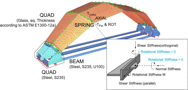
Each fitting was idealized using a system of four linear springs, capturing the three translational degrees of freedom as well as the rotational stiffness around the glass edge (compare Fig. 4). As was shown in the work by Fildhuth in general, the load is transferred through the brackets and only a limited area of the inserted T-bar is activated under loading. The bending stiffness is primarily achieved through the flange of the T-bar, which is laminated to the glass edge using the same structural PVB interlayer as used for the main glass lamination. Two possible load paths under bending have been identified by Fildhuth et al. (2022) for the local condition: A) In a conservative approach, bending is resisted through a force couple formed by tension in the laminated vertical web of the steel fitting and compression between the lower flange and the glass edge, assuming no edge bond contribution. B) the force couple develops between both flanges of the T-profile, assuming an intact edge bond, which enables a more efficient bending load path. When extending the insert linearly along the edge, the potential failure of the edge bonding in tension becomes negligible when an appropriate flange thickness and edge bond thickness is chosen. This was verified in the tests shown in Sect. 4.3 and is accounted for in the analytical model in Sect. 4.1. The global shell model was used to investigate influences of varying rotational stiffness on the structural response of the shell. The results are displayed in \* MERGEFORMAT Fig. 5. As a load case dead weight of the structure was considered, influencing the equivalent thickness of the glass elements. For the translational spring stiffnesses representative of the fitting in the early stage of the project, when the study was made, values were taken from Fildhuth et al. (2022). Throughout the course of the project tensile and shear tests were performed showing that the chosen values were acceptable.
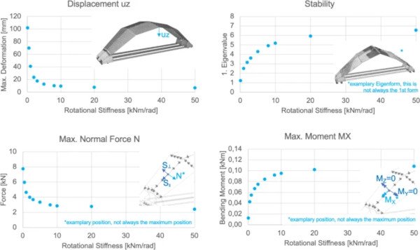
The figure illustrates the sensitivity of several parameters including the maximum vertical displacement at the center outer edge of the shell, the first eigenvalue as indicator of the system’s stability, as well as the maximum tensile force N and bending moment Mx of the fittings to changes in rotational spring stiffness of the locally modelled springs (compare Fig. 4).Footnote7 The results consistently show that low rotational stiffness significantly affects all parameters. As stiffness increases, the curves for displacement, eigenvalue, tensile force, and moment begin to plateau indicating a decreasing sensitivity to further stiffening. This implies that lower stiffness levels demand a more robust fitting design, capable of withstanding higher tensile and compressive loads.
4 Determination of the fitting’s rotational stiffness for the structural calculations
The linear fitting shows promising advantages in terms of force distribution and rotational stiffness, yet the performance must be quantified. In \* MERGEFORMAT Fig. 4, all degrees of freedom are displayed. Initial tension and shear tests confirmed that the normal and shear stiffness of the new linear fitting is comparable or superior to that of the local solution. However, preliminary analysis indicated that the rotational stiffness—particularly under bending—would be decisive for overall shell performance in frameless glass shells in general and specifically for the mockup at its unsupported edges. Therefore, the core focus of this study lies in quantifying the bending behavior of the developed connection and exploring its influence on global structural response. For the load-bearing capacity the IGU setup was neglected.
For that, in a first step, an analytical approach (Sect. 4.1) was chosen to determine the rotational stiffness of the connection. Under the assumption that the rotational stiffness of the fitting in normal direction and orthogonal to the glass edge is negligible, the focus lies on the rotational stiffness around the edge of the glass. Using the analytical approach presented below, in a second step, parametric studies (Sect. 4.2) have been performed to systematically investigate the influence of flange and web thickness, thickness of the adhesive in the interlayer and at the glass edge, glass thickness, inserted depth of the fitting web as well as the influences of temperature and load duration. In order to evaluate the accuracy of the analytical approach, mechanical tests (Sect. 4.3) were performed and the obtained experimental stiffnesses were compared with the analytically calculated ones and to the data published by Fildhuth et al. (2022) for the local fittings. In addition, failure mechanisms are presented.
4.1 Analytical approximation of the rotational stiffness
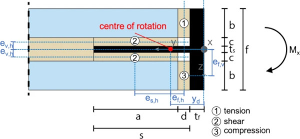
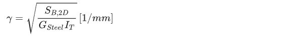
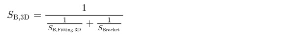
The bending stiffness can be considered as a series connection of the stiffness of the bracket and the resulting torsional stiffness of the elastically bedded beam representing the stiffness of the linearly laminated fitting. The bedding is assumed to be a linear spring with stiffness SB,2D. In simplified terms, the bolt stiffness is neglected, as the preloaded bolt only contributes to the drop in stiffness when its preload is exhausted and the brackets lose contact. The relevant parameters used in the equations below are given in \* MERGEFORMAT Fig. 6.
4.1.1 Stiffness of bracket
The stiffness of the bracket is

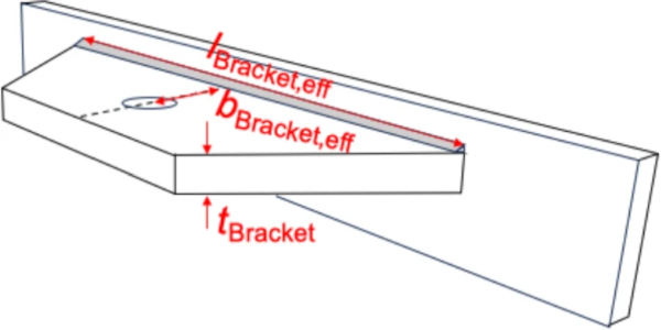
where ESteel is the Young’s Modulus of the steel insert, tBracket is the thickness of the bracket, lBracket is the length of the bracket and bBracket,eff is the effective width of the bracket. The latter is approximated by the width in the middle between the height of the hole and the welded seam (Fig. 7).
4.1.2 2D rotational stiffness of the fitting
The 2D torsional stiffness is calculated from a rotation around a pivot point to be determined.
If the fitting is considered rigid and the thickness of the PVB layers is considered low, the position of the pivot point is calculated in a highly simplified manner from the force equilibrium of eight springs connected in parallel. However, this neglects the bending stiffness of the web (the bending stiffness of the flange can be regarded as infinite anyway) and the spatial expansion of the springs.
Delivers a ratio of

with

which leads to
and
Thus the pivot position can be determined to be

In the z-direction, the pivot point lies on the center axis of the bar due to equilibrium.
The rotational stiffness becomes

4.1.3 Torsional stiffness of the fitting
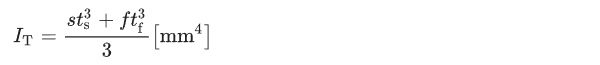
Assuming a thin-walled cross-section, the torsional stiffness of the fitting is calculated approximately as follows
4.1.4 3D Rotational Stiffness of the fitting
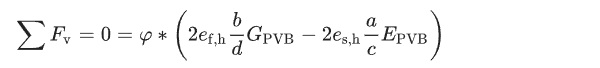
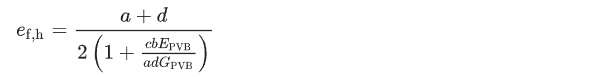
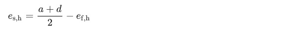
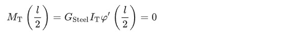
The 3D torsional stiffness can be calculated from the elastic support around the longitudinal axis. The bending moment is calculated as follows:
![]()
The restoring force results from the bedding:
![]()
Equilibrium leads to
![]()
and the differential equation
![]()
with
gives the general solution
![]()
when inserting the boundary conditions, we get

and
which results in
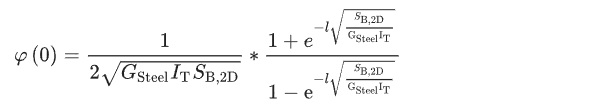
in 1/Nmm. The stiffness is
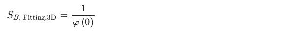
in Nmm/1.
4.1.5 Resulting rotational stiffness
The resulting bending stiffness is calculated from the series connection of the lug stiffness and the 3D torsional stiffness of the fitting as follows
4.2 Parameter influence analysis
Investigations on laminated fittings with different geometries by Yersin (2020) and Fildhuth et al. (2022) implicate that several geometric parameters effect the performance of the fitting. In order to evaluate these effects a systematic parameter study was performed using the equations derived in Sect. 4.1. The Young’s Modulus of the stainless steel fitting was chosen to 200.000 MPa whereas the properties of the Structural PVB, that are load and temperature dependent were taken from the datasheet (Eastman Chemical Company, Saflex Datasheet (2020)). The following reference configuration builds the basis of the study: temperature: 20 °C, load duration: 1 min, structural shear relaxation modulus G(t = 1 min, T = 20 °C) of PVB: 185 MPa, web thickness: 1.5 mm, flange thickness: 5 mm, PVBweb: 0.76 mm, PVBedge: 1.52 mm, web depth: 23 mm, glass thickness: 10 mm.Footnote8
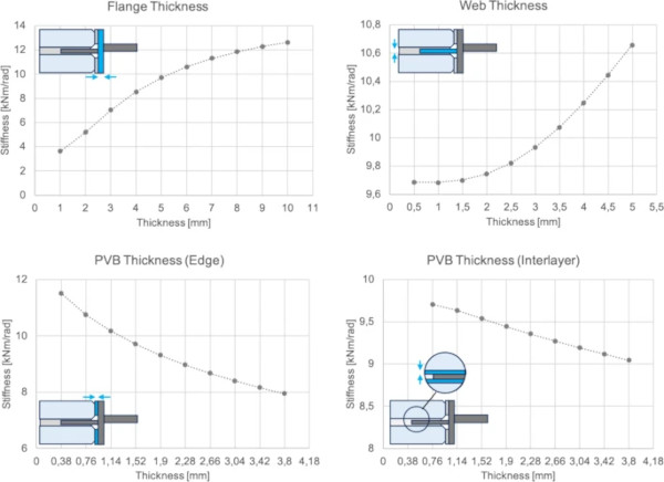
The results are presented in \* MERGEFORMAT Figs. 8, 9. In a first step, flange thickness, web thickness as well as the thickness of the PVB along the web and at the glass edge have been varied at a constant temperature of 20 °C.
For the flange thickness, the stiffness shows a positive correlation with increasing dimensions. It improves considerably with greater flange thickness, underlining the critical role of the flange in ensuring resistance against bending deformations, and especially torsion. A similar trend is observed for the web thickness where the rotational stiffness of the metal fitting increases with rising numbers of the web thickness. Yet, the effect is small as the realistic range for web thickness variation is limited (around 1 kNm/rad). In addition, a thicker web requires a thicker interlayer as well, which results in a much softer global response of the laminated glass pane. This may not influence the rotational stiffness itself, yet the displacement of the global shell grows. The same structural response thus would require thicker glass which makes the structure heavier. It increases the material use of the interlayer which is questionable from a sustainable point of view. The final thickness of the web was chosen as 1.5 mm for the mockup. As expected, an increase in PVB thickness in the web region results in a reduction in stiffness, suggesting that a thicker PVB interlayer reduces the overall rotational stiffness of the connection. A similar effect is observed when analyzing PVB thickness in the flange region, where increasing the interlayer thickness leads to a decrease in rotational stiffness. While this negatively effects the bending capacity of the connection, it reduces stress concentration, which can avoid adhesive failure at the flange/glass edge.
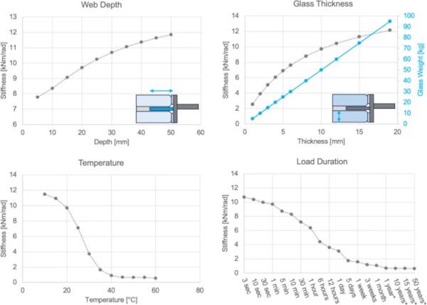
An increase in the depth of the web of the fitting in the interlayer leads to a continuous increase in the rotational stiffness. In contrast to this positive effect, a higher web depth increases the visible depth of the connection counteracting aesthetic appeal and frameless appearance.
As expected, an increase in glass thickness leads to a steady increase in bending capacity which makes sense as increasing glass thickness also results in a larger flange width and thus more contact area to transfer a bending moment which is taken by a force pair as described in Sect. 3.2. While glass thickness is thus of high importance in the performance of the fitting solution, glass weight significantly affects dead weight (compare \* MERGEFORMAT Fig. 9, upper right graph) and thus induces higher loads that need to be transferred through the connection. Moreover, it may affect the installation.
The stiffness of the connection is significantly affected by the temperature and load duration. As typical for most PVB interlayers, a massive decline in stiffness is found at about 25 °C for the whole connection which reduces its ability to transfer forces effectively. In addition, the time-dependent viscoelastic behavior of the PVB interlayer plays a major role in stiffness degradation. For applications with long term use, this is of tremendous importance. In this respect, a low dead load is of advantage. Yet, this makes a shell more susceptible to local forces.
4.3 Testing
4.3.1 Test setup
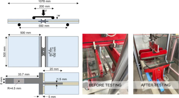
For the experimental determination of the bending stiffness four-point bending tests were performed using a universal testing machine at the material testing facility MPa Darmstadt. The tests were performed displacement-controlled at a rate of 10 mm/min. The geometry of the specimen is illustrated in \* MERGEFORMAT Fig. 10. Four test specimens, consisting of pairs of 2 samples connected by fitting bolts were tested until either failure occurred or a vertical displacement of 150 mm was reached. The distance of the supporting rollers is 550 mm and was chosen to counteract the influence of dead load. A schematic of the setup is shown in \* MERGEFORMAT Fig. 10.
4.3.2 Specimen description
Each test specimen consists of a 500 mm long double-laminated float glass beam (dimensions: 500 mm × 500 mm, glass setup: 2 × 10 mm heat-strengthened glass, 4 × 0.76 mm structural PVB), with a T-shaped stainless-steel fitting laminated into the edge. The insert geometry (compare Fig. 10, left) corresponds to the developed linearly laminated profile, manufactured via laser welding and with a surface treatment prior to lamination. In this respect it should be noted, that the surface roughness and surface condition of the metal fittings and the glass specimens has not been determined in the project.Footnote9 Any difference in actual surface area bonded by the interlayer may have influenced at which interface failure occurred. Further studies will need to investigate this in more detail. The surface conditions of the metal fittings (e.g. Rz, Rsm) and the surface finishing method (mechanical polishing, electro polishing, pickling) are essential for ensuring a strong bond between the PVB interlayer and the stainless steel fitting.
In difference of the final geometry that was realized in the mockup, the test specimen were manufactured with fitting holes, not as oversized holes that were needed for tolerance compensation in the real-life mockup. The flange thickness was 3 mm, and the web thickness was 1.5 mm. The insert protrudes 20 mm into the laminated area. The bracket is mechanically connected to the insert via M8 bolts.
4.3.3 Testing procedure
The tests were performed displacement-controlled at a rate of 10 mm/min. The geometry of the specimen is illustrated in Fig. 10. All tests were performed at 20 ± 2 °C and a relative humidity of 50 ± 15%. 4 test specimens, consisting of pairs of 2 samples—connected by fitting screws—were tested until either failure occurred or a vertical displacement of 150 mm was reached. The distance of the supporting rollers is 550 mm and was chosen to counteract the influence of the specimens’ dead load. A schematic of the setup is shown in Fig. 10.
4.3.4 Results
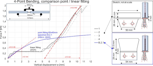
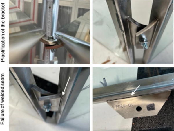
The tests showed consistent mechanical behavior across all specimens. The force–displacement curves were approximately linear in the elastic range (Region A, Fig. 11), followed by a softening plateau which corresponds to the range in which plastic deformation is observed in the bracket (Region B, Fig. 11, First row in Fig. 13). In Fig. 12, an excerpt of the tests results in the elastic range are plotted against data for the local fitting, investigated by (Fildhuth et al. 2022). The red lines indicate the average slope of the curves. The latter reveal, that the measured rotational stiffness for the linear fitting of given dimensions (compare Fig. 12, upper sketch on the right) is approximately twice as high as for the local fitting (dimensions, Fig. 12, bottom sketch on the right).
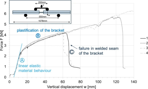
Region C in Fig. 11 represent the point at which failure occurred. Importantly, no glass fracture and no delamination was observed in any of the conducted tests, indicating that the glass itself remained structurally intact throughout. As shown in Fig. 13 (lower row), the abrupt drop in stiffness observed in this region is attributed to the failure of the laser-welded seam within the metal insert. This failure mode could lead to a sudden and brittle failure in practical applications and was therefore subjected to further analysis.
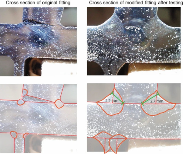
To investigate the weld integrity, one of the failed fittings was extracted from the laminate and subsequently sectioned and ground to expose the welded cross-section (Fig. 14, left). The examination revealed that the weld geometry and penetration in the test specimens were insufficient for application in load-bearing components. As a result, the weld thickness was increased in the fittings produced for the Glasstec mockup to ensure adequate structural performance (Fig. 14, right).
The rotational stiffness of the linear fitting, calculated using the force–displacement data in the linear elastic range (compare Fig. 12), is 6 kNm/rad. Using the analytical solution presented in Sect. 4.1 a rotational stiffness of 11 kNm/rad was determined. Hence, the analytical solution overestimates the stiffness by a factor of about 2.
5 Realization of the mockup
5.1 Manufacturing of the mockup elements
The manufacturing of the laminated glass elements for the mockup presented several challenges, primarily associated with the limited accuracy of the metal fittings provided for the mockup. The latter was a consequence of time issues and non-standardized production technique. Further investigation is necessary in this field. Another key challenge was to accurately cut the required interlayer geometry. As laser cutting was not able to provide sufficient accuracy for the size of the interlayer foil (up to approx. 2 × 2 m) and could not provide controlled clean room conditions, the PVB interlayer as well as the PVB slices for the edge laminate were cut manually. In contrast to the test specimen, where 2 × 0.76 mm slices were laminated at the edge of the glass, the massive distortions of the fittings for the mockup resulted in varying numbers of PVB slices along segments of the edge. Therefore, the PVB slices along the edge required precise fixation during lamination to guarantee proper adhesion. While for the temporary mockup this was not further investigated, testing is necessary to study effects of fixation parameters.
Another key requirement was the precise mutual alignment of the two glass panes during lamination to prevent offsetting and ensure uniform load transfer across the fitting interface. However, deviations from the ideal fitting geometry occurred due to residual stresses induced by the laser welding process, particularly in the case of longer fittings. These stresses led to distortions in the metal inserts, making accurate placement more difficult. The production method of the fitting needs further investigation in the future but was out of the scope of the project.
During lamination, air bubbles formed in the vicinity of the laminated fittings, observed in both test specimens and final mockup components. While in the tests, the bubbles did not distort nor influence results in any way, this needs to be further investigated.Footnote10 Again, the bubble formation is attributed to geometric irregularities at the glass-metal interface, which impede the uniform application of contact pressure and promote air inclusions during the autoclave process. One of the most challenging aspects of the process was the need to fix both the metal insert and the structural PVB interlayer at the glass edge with high positional accuracy prior to lamination.
While the exact manufacturing techniques and process parameters remain proprietary to the producer, it is known that certain measures—such as increased lamination time—were implemented to improve bond quality and reduce defects. These adaptations underline the importance of process control and fitting design in achieving high-performance laminated joints suitable for structural applications.
5.2 Assembly concept
In the following the steps during assembly of the shell are described including challenges that had to be taken care of:
- Steel substructure assembly In a first step the steel substructure needed to be assembled. A major challenge during this phase was ensuring the accurate spatial positioning of all steel components. Joints in the U-profiles using welded cap plates and steel plates of different thicknesses served to allow tolerance compensation after the glass shell is mounted.
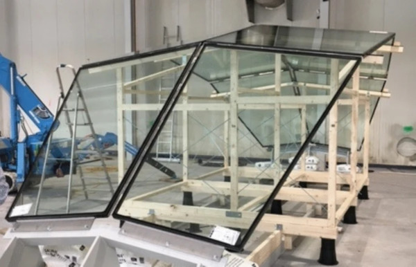
- Timber scaffolding As the loadbearing behavior is only activated after installation is completed, a full scale scaffolding was used throughout the installation to limit unwanted forces onto the fittings during the construction and guarantee accurate positioning of every element. Adjustable feet allowed for correct positioning. The scaffold is shown in Fig. 15.
- Glass panel installation Two mobile cranes, were used to lift and position the laminated glass panels. The ability to move two panels simultaneously was essential for fine alignment. In a next step the positioning and mechanical bolting of the panels was carried out using the developed metal fittings. Once aligned with each other and relative to the substructure, sleeves of matching tolerances were inserted, and the bolts were tightened to the specified torque values based on structural calculations.
- Tolerance management in the fitting system The upper lugs of the bracket system featured standard 9 mm boreholes. To compensate for possible tolerances and ensure constructability, the lower connection was designed with 17 mm oversized holes, i.e. tolerances of 4 mm in any direction could be accounted for. Initially, these were to be filled using injection mortar. However, for the mockup, steel rings in five precision tolerance classes were used instead, offering a dry and reversible solution without curing time, suitable for a temporary installation on the trade fair.
- Removal of scaffolding Following installation, the timber substructure was carefully lowered using the adjustable feet. A slight settlement of the glass panels was observed at certain locations but remained stable without further deformation, indicating the system’s ability to accommodate minor internal stresses and tolerances.
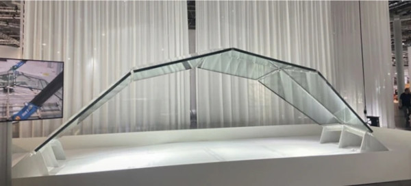
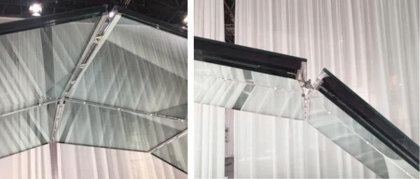
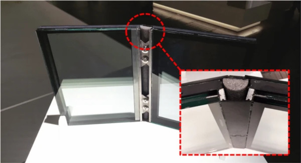
The installed mockup at the Glasstec trade fair is given in Fig. 16. A more detailed photography, zooming into the linear fitting is displayed in Fig. 17. Due to time issues and cost limitation the mockup did not showcase measures for thermal insulation. Fig. 18 shows a potential customized version of the fitting how the connection could be sealed. Currently the project team investigates this aspect in more detail and is performing thermal simulations and is preparing climate chamber tests.
6 Summary and outlook
This paper introduces a novel linearly laminated fitting for the structural activation of glass elements in frameless shell structures. The concept builds on previous research by Fildhuth et al. (2022) and Marinitsch (2015), combining continuous load transfer with mechanical brackets for tolerance management and reversible assembly. The developed fitting demonstrated increased rotational stiffness and ductile failure behavior without inducing glass breakage or delamination, offering a structurally robust and buildable solution.
The experimental investigations confirmed a rotational stiffness of 6 kNm/rad (linear-elastic regime), which proved sufficient for the mockup geometry. A comparison to the analytical model revealed, that the latter is overestimating the stiffness by a factor of 2. The applicability of the stiffness level in real-world scenarios, however, strongly depends on the specific project context. In geometrically favorable shell configurations—where loads are primarily carried through membrane action—only limited rotational stiffness may be required. Conversely, in applications subjected to significant wind or thermal loads, the demands on the fitting increase. In such cases, the rotational stiffness can be adapted through geometric modifications, such as increased flange thickness (compare parameter study, Sect. 4.2) or reduced bracket spacing. Special attention must be given to thermal actions, as the viscoelastic behavior of the structural interlayer (PVB) leads to pronounced stiffness reductions at elevated temperatures. Nonetheless, as indicated in Fig. 5, the influence of rotational stiffness on global structural performance exhibits a plateauing behavior beyond a certain threshold. This insight enables the derivation of project-specific design targets using the analytical model and supports an efficient balance between structural capacity, fabrication complexity, and material use.
The results presented in this study form a strong foundation for the future application of linearly laminated fittings in glass shell structures. While the current analysis conservatively assumes linear-elastic bracket behavior, further optimization may intentionally harness plastic deformation to enhance ductility and redundancy under extreme loading. This opens up new design opportunities for controlled post-yield performance.
The fabrication process—particularly the laser welding and lamination of the inserts—has proven feasible at scale but offers further potential for refinement. Improving flatness through optimized welding parameters and surface treatments can enhance geometric accuracy and bonding quality. With minor adjustments, consistent and high-quality integration of fittings appears well within reach.
Beyond mechanical performance, the integration of the fitting into insulating glass units offers exciting potential for combining structural function with building envelope requirements. Long-term durability under environmental exposure, thermomechanical behavior under thermal loading, and design solutions for thermal bridging represent promising avenues for future research. These investigations will support the development of a robust, scalable, and aesthetically integrated connection system—positioning laminated metal fittings as a key enabler for transparent, materially efficient, and architecturally ambitious glass structures.
Data availability
The data will be available at the data base of the Federal ministry for Economic Affairs and Climate Action of Germany as it is part of a research project which needs to be reported on after completion in August 2025.
Notes
- Titanium exhibits a coefficient of thermal expansion of approximately 9 × 10⁻⁶ K⁻1, which is notably closer to that of glass (∼9 × 10⁻⁶ K⁻1) than stainless steel (∼12 × 10⁻⁶ K⁻1), making it particularly well-suited for structural glass applications such as laminated shell structures. However, owing to its substantially higher cost, titanium was deemed economically unviable for broader application and was therefore excluded from the scope of the present study.
- The metal inserts were 1.5 mm thick and ranged from 40–60 mm in width and depth.
- In this context, ‘linear’ is to be understood as a continuously laminated metal insert along the edge of a laminated glass pane.
- The research project focused on the development of a connecting solution for frameless glass shell structures. Yet, the developed fitting has the potential of also being applied for other structural glass constructions, like folded plate structures.
- The thermal load case presents a particular challenge for laminated glass–metal composite structures, as the mismatch in thermal expansion coefficients between glass and stainless steel induces stress within the interlayer under temperature variations. To account for this in project-specific applications, it must be ensured that the resulting interlayer stresses remain within the material’s allowable strength limits. Should these limits be exceeded, the integration of thermal expansion joints—e.g.,, by limiting the maximum length of individual fittings—becomes necessary. In the context of the present mock-up (compare Sect. 3), however, numerical analyses demonstrated that no expansion joints were required under the investigated environmental conditions.
- This is true for the mockup shown at the trade fair as no high temperature differences were expected. In case of application in e.g., roofs exposed to radiation or partial shading, thermal stress needs to be accounted for and could require segmentation.
- The following parameters were kept constant in the model: Normal stiffness (in tension: 15 000 kN/m, in compression: − 1000 000 kN/m, transversal stiffness (parallel and orthogonal to the edge: 1000 000 kN/m), equivalent glass thickness for load case ‘dead load’: 13.4 mm.
- The geometric parameters are displayed in Figs.8, 9.
- According to the fitting manufacturer, the mean surface roughness (Rz) of the cold-rolled sheet with a thickness of 1.5 mm is 0.23 µm. Pickling would not have altered the surface roughness. Prior to lamination, the glass panels were washed in a vertical glass washing machine. Immediately prior to lamination, the glass surface was cleaned manually with a lint-free liquid and water with a conductivity of less than 10 µS. No mechanical treatment was applied.
- For comparison, commercially available steel and aluminum T-profiles (as drawn, non-welded materials) were laminated in the same process. As a result, a bubble-free metal–glass bond was achieved.