demonstrator at Glass Technology Live during Glasstec 2024 (© Cas Maertens).")
This paper was first presented at GPD 2025.
Link to the full GPD 2025 conference book: GPD_2025_ConferenceProceedingsBook.pdf

Authors: Bert Van Lancker a,b, Cas Maertens a, Roman Wan-Wendner a, Jan Belis a
a. Ghent University, Belgium
b. Vitroplena, Belgium
Abstract
The major drawback of adhesively bonding glass to conventional concrete is the brittle nature of both materials, i.e. the bonded substrates. However, with the development of fibre-reinforced concrete (FRC) and FR ultra-high performance concrete (UHPC), toughness and ductility of this type of substrate is significantly enhanced. The possibility to develop structurally bonded glass-to-concrete applications using FRC and FR UHPC is unlocked as such. FR (UHP) concrete steps bonded between glass stringers, glass balustrades bonded to a FR (UHP) concrete slab, sandwich panels consisting of a FR (UHP) concrete core and glass faces, T-beams consisting of a FR (UHP) concrete flange and glass web are just a few of such promising applications. In this research, the aim is to demonstrate the potential of these structurally bonded glass-to-concrete applications considering real-world design situations. By means of geometrically and material nonlinear finite element (FE) analyses, the mechanical performance of applications using (annealed and thermally toughened) laminated glass with structural pvb-interlayers, steel fibre-reinforced ultra-high performance concrete and twocomponent epoxies, is investigated. For the FR (UHP) concrete, an elastic-plastic material model is derived from experimental tests and implemented in the FE model. As an environmentally conscious solution, a cement-free FR UHPC with a carbon footprint less than 20% of conventional UHPC is investigated. This paper confirms the potential of developing structurally bonded glass-to-concrete applications for real-world design situations. The production of a large-scale demonstrator afterwards validates the transformative potential of the structurally bonded glass-to-concrete concept in terms of increased structural efficiency and aesthetic appearance, and provides a path towards sustainable, high-performing hybrid glass-concrete structures.
Article Information
- Published by Glass Performance Days, on behalf of the author(s)
- Published as part of the Glass Performance Days Conference Proceedings, June 2025
- Editors: Jan Belis, Christian Louter & Marko Mökkönen
- This work is licensed under a Creative Commons Attribution 4.0 International (CC BY 4.0) license.
- Copyright © 2025 with the author(s)
1. Introduction
The application of structural glass elements is key in today’s strive for maximum transparency of buildings and building components. The use of glass as structural element, however, is not evident. Glass is a brittle material with limited toughness, can fracture due to defects such as material imperfections or inclusions and has a strength which decreases in time due to increases in surface damage. To overcome undesired failure behaviour, ductility can be introduced in the element by including other materials. Typical combinations are glass-metals (typically steel or aluminium), glasstimber, glass-glass-fibre reinforced polymer (GRFP), glass-plastics and glass-concrete (Martens, Caspeele & Belis, 2015). These hybrid elements or glass composite elements typically make use of adhesive bonds between the different materials as such connections transfer forces more uniformly and as additional treatments of the glass elements, such as drilling or tempering, are not necessarily required (Van Lancker, Dispersyn, De Corte & Belis, 2016).
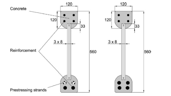
An example of a hybrid glass-reinforced concrete element is an I-shaped beam with a web made from laminated glass and flanges composed of reinforced ultra-high performance concrete (UHPC) as investigated by Freytag (2004) and as depicted in Fig. 1. The laminated glass web composed of three 8 mm thick fully tempered glass plates was placed in a mould in which the concrete for the flanges was poured. The glass was pretreated by roughening the contact surfaces. The top flange was reinforced by steel rebars, whilst the bottom flange was either reinforced with steel rebars or by prestressing tendons. Four-point bending tests demonstrated the very stiff and linear behaviour of the hybrid beam until cracking of the outer glass panes, as well as its high load-bearing capacity. On the other hand, due to the brittle nature of both glass and conventional concrete, the beam fails instantly when the glass web breaks near the supports as shear forces can only be transferred through the bottom concrete flange which is not designed for this (Martens et al., 2015). Maertens, Van Lancker, Proia, Wan-Wendner and Belis (2024) investigated glass-to-concrete joints through three-point bending tests. Different types of adhesives (epoxy-based, acrylic-based and hybrid polymer-based) were tested, as well as different configurations of the adhesive bond between the conventional concrete and an annealed float glass pane at the bottom, hence activated in tension. Higher failure loads were obtained with stiffer adhesives and larger bond areas as shear transfer between the materials is increased. Brittle failure, however, was observed for all types of adhesives: a thin layer of the concrete substrate was delaminating. Other failure modes can be obtained by alternative concrete surface preparations which expose the aggregates (Chen et al., 2019). Nevertheless, the brittle nature of each failure mode will remain.
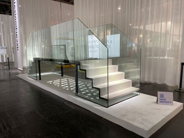
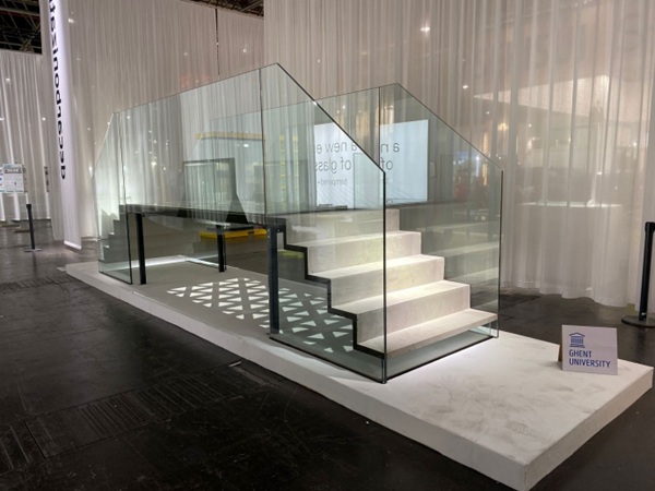
The aforementioned results from literature demonstrate the major drawback of adhesively bonding glass to conventional concrete, i.e. the brittle nature of both substrates. Fortunately, (steel) fibre-reinforced concrete ((S)FRC) and (steel) fibre-reinforced ultra-high performance concrete ((S)FR UHPC), with enhanced toughness and ductility, provide new potential for hybrid glass-concrete elements. Compared to conventional concrete, SFR UHPC has an increased tensile strength (up to 2.5 times) and fracture toughness (fracture resisting properties). An increased flexibility and plasticity of the concrete (and as such a higher durability and efficiency performance) is obtained as well (Shemirani, 2022). As such, the possibility to develop structurally bonded glass-to-concrete applications using SFRC and SFR UHPC is unlocked. SFR UHPC steps bonded between glass stringers, glass balustrades bonded to a FR UHPC slab, sandwich panels consisting of a FRC core and glass faces, T-beams consisting of a FRC flange and glass web are just a few of such promising applications. A large-scale demonstrator (G2C or glass-to-concrete), incorporating all these examples of potential applications revealed during Glass Technology Live at Glasstec 2024 demonstrated the transformative potential of the structurally bonded glass-to-concrete concept in terms of increased structural efficiency and aesthetic appearance (cfr. Fig. 2). As an environmentally conscious solution, the concrete of the stairs was a cement-free FR UHPC with a carbon footprint less than 20% of conventional UHPC. The G2C research project and G2C showcase provide a path towards sustainable, high-performing hybrid glass-concrete structures.
The aim of this paper is to demonstrate the potential of structurally bonded glass-to-concrete applications considering real-world design situations. By means of geometrically and material nonlinear finite element (FE) analyses, the mechanical performance of potential applications using (annealed and thermally toughened) laminated glass with structural pvb-interlayers, steel fibre-reinforced concrete (SFRC) and steel-fibre reinforced ultra-high performance concrete (SFR UHPC) and twocomponent epoxies, is investigated.
2. Applications
The research project glass-to-concrete (G2C) wants to demonstrate the potential and possibilities of structural adhesive bonding of laminated glass to steel-fibre reinforced (ultra-high performance) concrete. The following potential applications, which were demonstrated during Glass Technology Live at Glasstec 2024, are further investigated in this paper.
A self-supporting 1.3 m wide hybrid glass-concrete staircase consisting of the following elements:
- 1.30 m wide SFR UHPC stairs (C90/105, SC class 8, ductility class b) with 5 steps (riser = 20 cm, tread 25 cm)
- 2.155 m by 1.25 m 1010.4(TTG,DG41) stringers and balustrades, i.e. laminate made from two individual thermally toughened glass (TTG) plates of 10 mm and 4 structural PVB (DG41) interlayers (4 x 0.38 mm = 1.52 mm).
- 1.24 m by 0.21 m 88.4(ANG,PVB) support of the first step, i.e. laminate made from two individual annealed glass (ANG) plates of 8 mm and 4 standard PVB interlayers (4 x 0.38 mm = 1.52 mm).
A two-sided supported 3 m span hybrid glass-concrete floor panel with a width of 1.3 m consisting of:
- 1.30 m by 3.00 m SFRC slab (C30/37, SC class 4, ductility class a) with a thickness of 80 mm;
- 1.29 m by 2.99 m 88.4(TTG,PVB) top plate, i.e. laminate made from two individual thermally toughened glass (TGG) plates of 8 mm and 4 standard PVB interlayers (4 x 0.38 mm = 1.52 mm);
- 1.00 m by 2.70 m 88.4(TTG,PVB) bottom plate, i.e. laminate made from two individual thermally toughened glass (TGG) plates of 8 mm and 4 standard PVB interlayers (4 x 0.38 mm = 1.52 mm);
- two curved 2.60 m by 0.18 m 88.4(ANG,PVB) glass beams, i.e. laminate made from two individual annealed glass (ANG) plates of 8 mm and 4 standard PVB interlayers (4 x 0.38 mm = 1.52 mm).
3. Materials
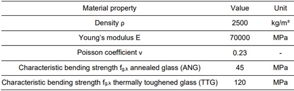
The material properties of glass are presented in Table 1. For calculations using the finite element method, a linear elastic material behaviour is adopted for this material.
Table 1: material properties of glass from EN 16612 (CEN, 2019).
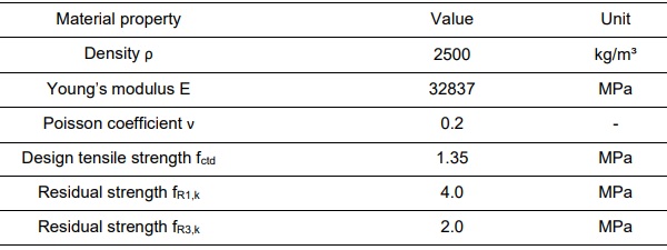
The material properties of steel fibre-reinforced ultra-high strength concrete (C90/105) and for steelfibre reinforced concrete (C30/37) are presented in Table 2 and Table 3. Strength characteristics of the ultra-high strength concrete are obtained from compression tests. Applying annex L of Eurocode 2 (CEN, 2023) allows for the determination of an elastic-plastic material law for this SFR UHPC. The SFRC can be categorised and annex L can be applied as well to determine an elastic-plastic material law. However, as no compression test results for the SFRC are yet available, linear elastic material behaviour is considered for initial design calculations.
Table 2: material properties of SFR UHPC C90/105 from experimental tests and EN 1992 (CEN, 2023).
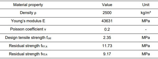
Table 3: material properties of SFRC C30/37 from EN 1992 (CEN, 2023).
The epoxy-based adhesive has an elastic modulus of 3500 MPa and a Poisson coefficient of 0.3. The characteristic tensile strength and characteristic concrete adhesion strength are provided by the manufacturer. Elastic material behaviour is attributed to the adhesive in finite element modelling. Alternatively, a tie constraint between glass and concrete can be assumed or a stress-slip model at the glass-concrete interface can be modelled based on Maertens et al. (2024).
4. Loads, load combinations and criteria
4.1. Loads
Loads acting on the different hybrid glass-concrete elements can be determined based on EN 1991 (CEN, 2002a). For the considered applications to be used in an interior public place, besides selfweight, the vertical live loads and the horizontal barrier loads conform EN 1991 are defined by:
- Vertical uniformly distributed load qk,v = 3 kN/m²
- Horizontal line load qk,h = 1 kN/m at the upper edge (H ≥ 1.1 m) of the balustrade
Remark that for local design considerations, point loads are defined as well. As the aim of this paper is to investigate the general structural response of the hybrid glass-concrete elements, only uniformly distributed loads are considered for now.
4.2. Load combinations
The hybrid glass-concrete structure is designed in correspondence with the principles of EN 1990 (CEN, 2002b) considering consequence class 2 (CC2). The considered limit state scenario is selected from CEN/TS 19100 (2021) and is chosen to be LSS-1. This implies that calculations are performed in the ultimate limit state (ULS), referring to strength, and in the serviceability limit state (SLS), referring to stiffness. The fracture limit state (FLS) is considered by selecting laminated safety glass, consisting of either annealed glass or thermally toughened glass. The post-fracture limit state (PFLS) is discarded due to the temporary nature of the structure, i.e. a demonstrator for an indoor fair.
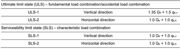
In the ULS, the fundamental load combination is considered for vertical loads. As such, the partial safety factors for unfavourable permanent and variable loads are respectively 1.35 and 1.5. For horizontal loads, the accidental load combination is selected and the partial safety factors are taken equal to 1 for the unfavourable permanent and variable loads. This because only a limited amount of people are allowed to simultaneously walk over the demonstrator. In the SLS, the characteristic combination is investigated. This results in the load combinations as presented in the table below.
Table 4: load combinations in correspondence with EN 1990 (CEN, 2002a).
4.3. Criteria
Ultimate limit state
In the ultimate limit state, glass elements are designed accounting for the design bending tensile strength according to EN 16612 (CEN, 2019) and CEN/TS 19100 (CEN, 2021) taking into account a load duration of 30 minutes. This results in the design bending tensile strength of annealed glass and thermally toughened glass equal to:
- σmax,ANG = 17.3 MPa
- σmax,TTG = 87.5 MPa
The concrete elements are designed accounting for the strength according to EN 1992 (CEN, 2023), which comprises compressive and tensile strengths according to the considered strength class, i.e. C30/37 and C90/105. For elastic-plastic calculations the plastic zones are investigated.
For the adhesive, the allowable stresses are taken equal to the bulk material strength or interface strength divided by a safety factor of 4. The values of the tensile strength of the adhesive, the glassadhesive and concrete-adhesive interface strength were provided by the adhesive manufacturer.
Serviceability limit state
Deflections in the SLS were limited to values which were determined based on a comparison between several technical guidelines, technical specifications and standards valid in Europe.
- Concrete steps: vertical deflection ymax = L/300 = 1300 mm/300 = 4.3 mm
- Hybrid glass-concrete floor panel: vertical deflection ymax = L/300 = 3000 mm/300 = 10.0 mm
- Balustrades: horizontal deflection at upper edge umax = 35 mm
5. Numerical analysis
5.1. Hybrid glass-concrete staircase
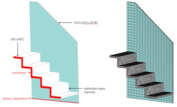
For the hybrid glass-concrete staircase, a finite element (FE) model is built in Ansys. Making use of the symmetry of the structure, only one half is modelled. The laminated 1010.4 (TTG,sPVB) glass panels are modelled as such, using a load scenario of 40°C and 30 minutes to determine the interlayer properties. The adhesive layer is physically modelled with a thickness of 1 mm. In the actual structure, the first step is supported and the last step can be. In the model, however, the first and last step are considered not to be supported. Glass and adhesive are modelled as linear elastic materials (cfr. paragraph 3), whilst the SFR UHPC is modelled as elastic-plastic material (cfr. paragraph 3). For the glass panes and the interlayer, quadratic solid shell elements are selected. The concrete is meshed using quadratic tetrahedral solid elements. Quadratic rectangular solid elements are considered for the adhesive, which has at least 2 elements over its thickness. Geometrically nonlinear static calculations taking into account large deflections are performed. Fig. 3 depicts the finite element model.
The maximum principal tensile stresses in the concrete stairs and in the adhesive for load combination ULS-1 (vertical uniformly distributed load) are presented in Fig. 4. The maximum principal tensile stress equals 0.95 MPa, which remains below the allowable tensile stress of 2.35 MPa as valid for linear elastic calculations. The maximum values appear at the bottom near the transition between the horizontal steps and the vertical risers. When performing analyses with different mesh sizes, the stresses remain more or less constant. By comparing the values with the allowable design stress (safety factor 4) for the tensile strength of the adhesive itself and the interface strength of the adhesive with glass and concrete, it is concluded that the adhesive bond is structurally performant. The definition of failure criterions applicable for these adhesive glass-concrete bonds is still the subject of ongoing research. Remark, that maximum stresses are present at the front of the first step and at the end of the last step. Both are assumed not to be supported, however, in the actual structure the first step is.
In the serviceability limit state, the maximum deflection of a step of the stairs for load combination SLS1 (vertical uniformly distributed load), equals 0.1 mm, which is lower than the allowable deflection of 4.3 mm.
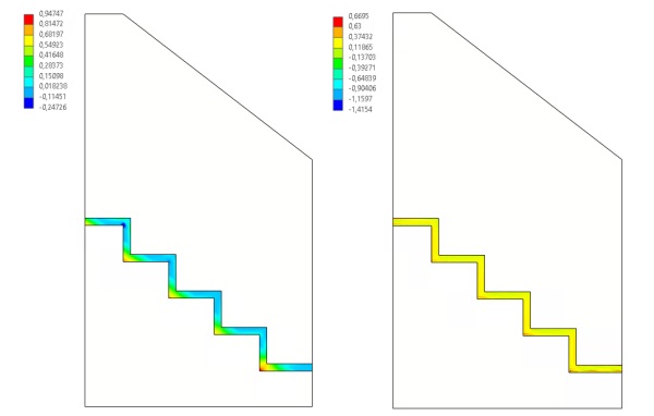
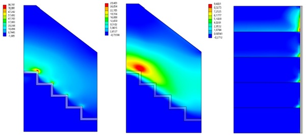
Fig. 5 depicts the maximum principal tensile stresses in the glass plates for the load combination ULS2 (horizontal line load). As stresses reach values up to the design stress of thermally toughened glass, the design of the glass elements is determined by this load combination as expected. Fig. 5 also depicts the maximum principal tensile stress and the plastic strain in the concrete for load combination ULS-2. A small plastic zone appears near the last step. The plastic zone, however, is not significant in size and does not affect the load-displacement graph of the balustrades significantly. As such, it is assumed the plasticity of the SFR UHPC enables the transfer of loads safely without failure and that the design as such is safe according to the design principles of the Eurocodes.
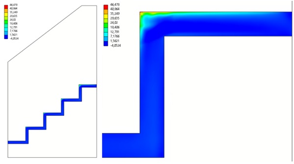
The maximum principal tensile stresses in the adhesive reach significant values as well, as depicted in Fig. 6. The stress concentrations that are present with values up to 46.5 MPa are below the inherent strength of the adhesive (material factor 1 for accidental load combinations). Nonetheless, with the current knowledge on the applied glass-concrete bonds it is not possible to determine whether or not the interface strength between glass and adhesive or between concrete and adhesive will be able to transfer these loads. Further research on bonded glass-concrete balustrades is therefore ongoing.
The deflection for load combination SLS-2 (horizontal line load) in the serviceability limit state equals 28.3 mm, which does comply with the requirement of a maximum deflection of 35 mm.
What the results demonstrate is that although the design for vertical loads appears to be ultraconservative, the design for horizontal loads determines the minimum required dimensions of the components to fulfil the structural requirements in the end. The vertical loads on the concrete stairs mainly load the adhesive layers in shear, i.e. a well-known stress state in glass-concrete bond for which structural performance can be assessed relatively easily. The horizontal line load at the upper edge of the glass panels on the other hand introduce a bending moment in the adhesive layer, and as such cleavage stresses in the adhesive. The assessment of the structural performance of the glass-concrete bond subjected to these cleavage stresses is more complicated and requires additional experimental tests which are currently ongoing.
5.2. Hybrid glass-concrete floor panel
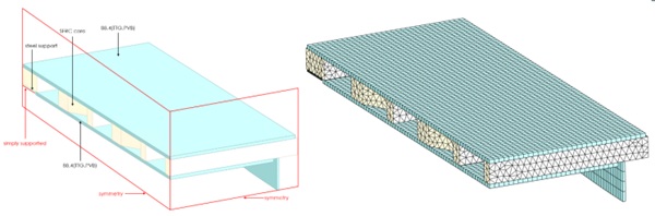
For the hybrid glass-concrete floor panel, a finite element (FE) model is built in Ansys. Making use of the double symmetry of the structure only one fourth is modelled. The laminated 88.4(TTG,PVB) glass panels bonded on top and at the bottom of the concrete core are modelled as a monolithic glass panel with an equivalent thickness that neglects shear transfer (shear modulus interlayer G = 0 MPa). The adhesive layer is not modelled physically, but instead the contact definition between glass and concrete implements a tie constraint. A steel support is modelled taking into account linear elastic behaviour (E = 210000 MPa, ν = 0.3), and hard normal contact and frictionless shear contact with the concrete. The concrete is modelled using linear elastic material behaviour (cfr. paragraph 3). Quadratic solid shell elements are used for the glass panels, quadratic tetrahedral solid elements are used for the concrete core and steel support. Geometrically nonlinear static calculations taking into account large deflections are performed. Fig. 7 depicts the finite element model.
The maximum principal tensile stresses in the top glass plate and bottom glass plate, and in the glass beam for load combination ULS-1 (vertical uniform load) are presented in Fig. 8. These stresses reach values of only 0.9 MPa and 2.8 MPa respectively, i.e. far below the allowable design stress of 87.5 MPa. This due to the height of the concrete core, i.e. 8 cm, to allow for the adhesive bonding of the balustrades, and due to the fusion of hybrid glass-concrete beams in the hybrid glass-concrete floor panel. The maximum principal tensile stress in this element reaches a value of 9.1 MPa, which results in a 53% use of the capacity of the glass beam. The maximum stresses in the bottom plate appear in the zone where the bending moment reaches its maximum. Near the supports, the stress distribution is more localised near the openings in the concrete core, i.e. where forces are transferred between glass and concrete via the adhesive layer. For the top plate, local tensile stresses are present near these openings as well.
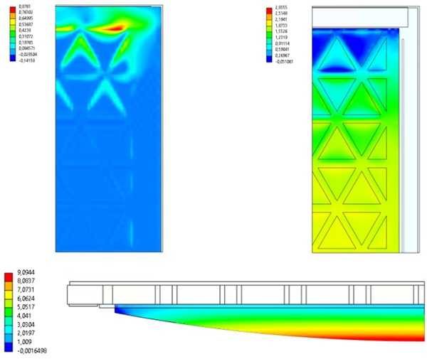
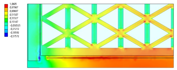
Fig. 9 depicts the maximum principal stresses in the concrete for load combination ULS-1 (vertical uniform load). The maximum value of 1.06 MPa remains below the maximum allowable design stress of 1.35 MPa. Stress concentrations also occur near the sharp corners of the openings, which in the actual structure are rounded to reduce these stress peaks. Remark that linear elastic behaviour for SFRC is considered. Taking into account elastic-plastic material behaviour in accordance with annex L of Eurocode 2 (CEN, 2023) for SFRC, a detailed study of the overall material use and general topology of the concrete core in terms of structural performance will result in a significant optimisation of the hybrid floor panel. For the demonstrator, the thickness of the concrete core is determined by the structural requirements of the balustrades bonded to its sides.
As the stresses near the interfaces of the glass plates and concrete core remain below the interface strength values divided by a safety factor of 4, the design is assumed to be safe in ultimate limit state. Next, stress-slip models derived from experimental tests will be implemented in the contact definition between glass and concrete, instead of a tie constraint which was used for now based on the experimental findings from Maertens et al. (2024).
In the serviceability limit state, load combination SLS-1 results in a deflection of 0.5 mm, which is significantly lower than the allowable deflection of 10 mm.
Again, the design for vertical loads appears to be overconservative. However, as balustrades are bonded to the sides of the concrete core its overall design is determined by the horizontal load combination acting on the balustrade. The presence of the glass beams also results in limited stresses in the top and bottom glass plate. Hence, actual applications of a hybrid glass-concrete floor or wall panel will be more slender and structurally optimised in terms of material use.
6. Conclusions and future work
This paper reports on the potential of structurally bonded glass-to-concrete applications, i.e. a floor panel and a staircase, considering real-world design situations. Geometrically and material nonlinear finite element analyses were performed to demonstrate the potential of the bonded glass-to-concrete concept when using steel fibre-reinforced (ultra-high performance) concrete. The use of SFRC and SFR UHPC for adhesive glass-concrete elements avoids the major drawback of adhesively bonding two brittle materials, as these materials demonstrate enhanced toughness and ductility. The applications of a hybrid glass-concrete staircase and a hybrid glass-concrete floor panel were selected.
Material properties were determined from standards, experimental tests and recommendations of the manufacturers. For SFRC and SFR UHPC, elastic-plastic material models could be derived for implementation in finite element software. Based on the design principles of the Eurocodes, the loads, load combinations and criteria were determined for this demonstrator. Important to notice is that no thermal loads were considered in the design, which are, however, fundamental for bonded glassconcrete applications. Especially for outdoor use (e.g. balustrades, façade panels, etc.) the adhesive bond has to ensure that differences in thermal expansion (due to differences in the linear coefficient of thermal expansion between the materials, but also the differences in thermal mass of the substrates) can be coped with safely, i.e. without failure of the structural bond.
For the application of a hybrid glass-concrete staircase, the design for vertical loads appeared to be ultraconservative. However, the design for horizontal loads determined the minimum required dimensions of the structural components in the end. Assessment of the structural performance of the adhesive layers subjected to shear was more simple in comparison with bonds subjected to cleavage stresses. Therefore, future work comprises an investigation on the importance of parameters, such as adhesive stiffness, bond width and bond thickness, on the structural performance, in terms of stiffness and strength, of the glass-concrete bond. Additional experiments on the application of bonded glassconcrete balustrades will be performed in the future as well.
For the hybrid glass-concrete floor panel, the design for vertical loads appeared to be overconservative as well. However, as balustrades are bonded to the sides of the concrete core its overall design was again determined by the horizontal loads acting on the balustrade. The presence of the glass beams also results in limited stresses in the top and bottom glass plate. Hence, the tie constraint as modelled to characterise the glass-concrete interface behaviour resulted in sufficiently accurate results (Maertens et al., 2024). However, future research aims to define stress-slip models for the interfaces of this (and other) adhesive(s) to enable a more accurate prediction of the structural response of the glass-concrete elements. As such, failure criterions for the substrates and the adhesive bond can be proposed as well. For this application, this will result in an optimised topology of the concrete core and optimised material use in general.
The production of a large-scale demonstrator based on the design presented in this paper validates in the end the transformative potential of the structurally bonded glass-to-concrete concept. This in terms of increased structural efficiency and aesthetic appearance, but it also provides a path towards sustainable hybrid glass-concrete structures when using cement-free UHPC.
Acknowledgements
The authors would like to acknowledge the support of fischerwerke GmbH & Co. KG and vitroplena bv during the G2C (glass-to-concrete) research project.
This research is supported by travel grant K122625N from Research Foundation Flanders – FWO.
References
CEN (2002a). EN 1991:2002: Eurocode 1 – Actions on structures. European Committee for Standardisation.
CEN (2002b). EN 1990:2002: Eurocode 0 – Basis of structural design. European Committee for Standardisation.
CEN (2021). CEN/TS 19100: Design of glass structures. European Committee for Standardisation.
CEN (2019). EN 16612:2019: Glass in building – Determination of the lateral load resistance of glass panes by calculation. European Committee for Standardisation.
CEN (2023). EN 1992: Eurocode 2 – Design of concrete structures. European Committee for Standardisation.
Chen, C., Li, X., Zhao, D., Huang, Z., Sui, L., Xing, F., Zhou, Y. (2019). Mechanism of surface preparation on FRPConcrete bond performance: A quantitative study. Composites Part B: Engineering, 163, 193-206.
https://doi.org/10.1016/j.compositesb.2018.11.027
Freytag, B. (2004). Glass-concrete composite technology. Structural Engineering International, 14(2), 111-117.
https://doi.org/10.2749/101686604777963991
Maertens, C., Van Lancker, B., Proia, A., Wan-Wendner, R., Belis, J. (2024). Investigation of glass-to-concrete adhesive joints through three-point bending tests. Challenging Glass Conference Proceedings, Vol. 9.
https://doi.org/10.47982/cgc.9.561
Martens, K., Caspeele, R., Belis, J. (2015). Development of composite glass beams – A review. Engineering Structures, 101, 1-15. https://doi.org/10.1016/j.engstruct.2015.07.006
Van Lancker, B., Dispersyn, J., De Corte, W., Belis, J. (2016). Durability of adhesive glass-metal connections for structural applications. Engineering Structures, 126, 237-251.
https://doi.org/10.1016/j.engstruct.2016.07.024
Shemirani, A.B. (2021). Effects of Fiber Combination on the Fracture Resistance of Hybrid Reinforced Concrete. Iranian Journal of Science and Technology, Transaction of Civil Engineering, 46, 2161-2172.
https://doi.org/10.1007/s40996-021-00703-x