
This paper was first presented at GPD 2025.
Link to the full GPD 2025 conference book: GPD_2025_ConferenceProceedingsBook.pdf

Author: Kateri Knapp, Arup, USA
Abstract
The design of glazing for the purpose of daylighting in museums must address an expanded set of performance criteria relative to typical glazing design. The replacement of the historic skylights which provide natural daylight to the European Paintings Galleries (A, B, & C Wings) and the replacement of the existing sloped, south-facing curtainwall that provides daylight to the Arts of Africa, Oceania, and the Americas (Michael C. Rockefeller Wing) at the Metropolitan Museum of Art in New York are presented as case studies in addressing these performance criteria. Design considerations including optical performance for art conservation and daylight quantity and quality management, structural performance to resist wind, self-weight, snow and access and maintenance loads, safety in the event of breakage, thermal performance, loads imposed on the existing historic structure, simplicity of procurement, maintenance, and replacement, and aesthetic considerations are examined. A summary and comparison of how the design considerations for these sensitive glazing replacement projects are addressed is provided through a discussion of the design, mock-up, and construction processes.
Article Information
- Published by Glass Performance Days, on behalf of the author(s)
- Published as part of the Glass Performance Days Conference Proceedings, June 2025
- Editors: Jan Belis, Christian Louter & Marko Mökkönen
- This work is licensed under a Creative Commons Attribution 4.0 International (CC BY 4.0) license.
- Copyright © 2025 with the author(s)
1. Project Background & Context
The Metropolitan Museum of Art (the Met) is located on the Upper East Side of Manhattan in New York City, situated within the boundaries of Central Park, with its most prominent façade facing “Museum Mile” of 5th Avenue. The Met is home to almost 500,000 works of art from across the world, spanning over a 5,000-year history. The encyclopedic nature and cultural significance of the collections attracts millions of visitors each year.
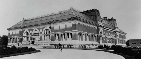
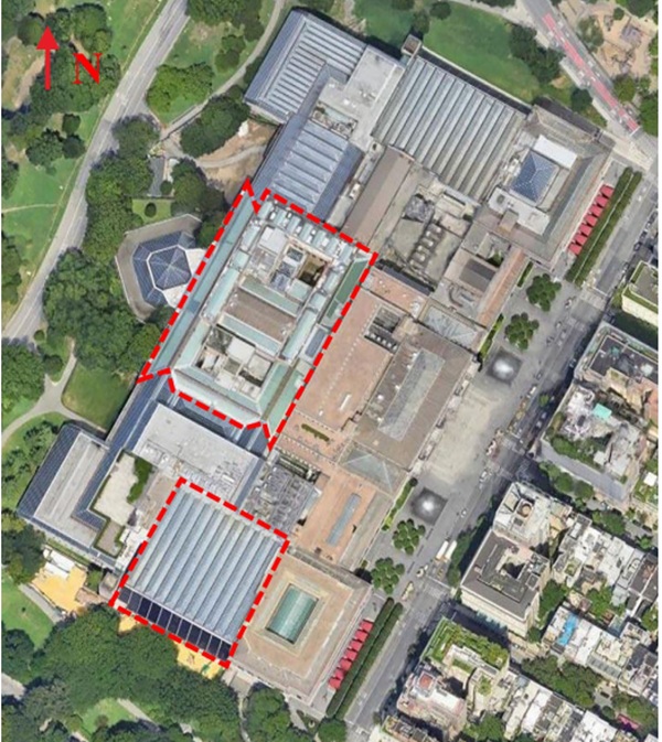
The building itself is a collection of twenty-one wings constructed in phases over a period of 100+ years. The oldest of these wings include the A, B, & C Wings (ABC Wings), built in the late 19th century. Numerous subsequent expansions have grown the building’s footprint, including the construction of the Great Hall with its widely recognizable Beaux-Arts façade along 5th Avenue, continuing through the architectural masterplan by Kevin Roche John Dinkeloo and Associates in the early 1970’s, finishing with the construction of the Kravis Wing in the 1990’s. The Met’s current footprint encloses approximately 195,000 m² (2.1 million ft²) of area, sheltered by a roof surface of over 46,400 m² (500,000 ft²)
While the building has undergone necessary general maintenance, renovations, and upgrades over the course of its history, the renovation of the ABC Wings, including the replacement of almost 2,800 m² (30,000 ft²) of skylights, redesign and replacement of the associated mechanical systems, and renovation the European Paintings Galleries is the first major infrastructure upgrade project of its kind and scale for the Met.
This project became the precedent which has marked the beginning of a series of major projects to enhance and improve the building’s energy performance in conjunction with gallery renovations and program development, as part of a planned $2 billion investment by the Met’s Capital Projects program. The next major project in this 20-year plan is the renovation of the Michael C. Rockefeller Wing (MCR Wing). The MCR Wing project includes the redesign of 3,700 m² (40,000 ft²) of gallery space which is home to the Arts of Africa, Oceania, and the Americas (AAOA) collections, replacement of the 1,100 m² (12,000 ft²) of south-facing sloped glazing, and major upgrades to the mechanical systems which serve this area of the building.
While both projects featured similar goals with respect to improving thermal and optical performance of the building envelope within the constraints of the existing geometry and historic structure, their specific contexts within the overall building, solar exposure, patron experience, art collections, and site access considerations resulted in dramatically different design results for the glazing selection.
2. Existing Conditions & Design Challenges: ABC Wings
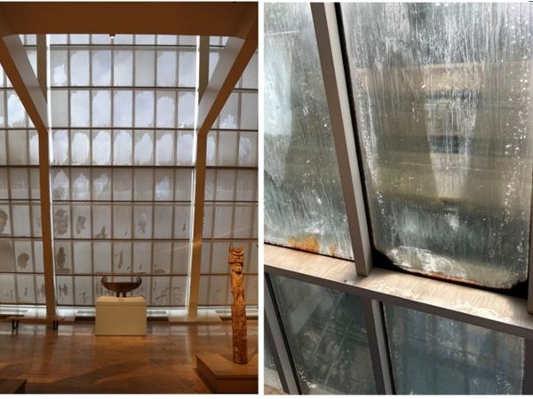
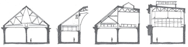
As is a common architectural configuration for museums of the late 1800’s and early 1900’s which rely on natural daylight for their galleries, the ABC Wings feature glass “laylight” ceilings which separate the patron experience of the gallery from the attic space and true building envelope above. The laylights conceal a back-of-house plenum which was originally intended to serve as a daylight mixing chamber including adjustable fabric louvers, and to provide a level of separation between the polished architectural space of the gallery and the back-of-house view of the building structure and skylight system. As mechanical systems and electric lighting were introduced, the attics’ function expanded to hide the growing MEP services above the laylight grids.
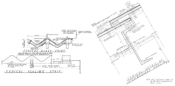
The varying roof geometries, solar exposure, status of existing louver operability, and mechanical ductwork distribution within the attic spaces ultimately led to a wide variety of daylight conditions in the galleries below. Key issues included high contrast between adjacent galleries, and “hot spots” of higher solar exposure on individual walls within some galleries. The original flat wired skylight glass had been replaced most recently in the 1930’s-1940’s with shingled, corrugated wire glass of approximately 6mm thick with gasketed joints which had long-since exceeded their service life. This single glazed envelope exhibited regular leakage challenge, extremely poor thermal and condensation performance, lacked UV control for the protection of the artwork below, and had limited structural integrity with several broken panels in areas of large snow drift loads and access and maintenance loading.
Key design challenges, considerations, and opportunities for the glazing replacement at the ABC Wings included:
- Stringent daylight quantity limits to maintain conservation requirements for the paintings and artwork, with targets focused on a combination of annual lux-hour exposure limits as well as minimizing instantaneous peak light levels seasonally.
- Critical goals for light quality and consistency throughout all galleries and over the course of the year, despite the range of solar exposures due to varying roof geometries and orientations and shifting sun angles throughout the year.
- Desire to retain the historic trusses and purlins with limited reinforcement. The historic structure would be required to support the weight of new skylight framing, new insulating glass with approximately 3x the original glass thickness, and updated wind and snow loads in accordance with the current code, so minimizing glazing and system weights needed to be balanced with thermal and condensation performance goals.
- Overhead glazing with slopes varying between 30-42 degrees from horizontal, required to be both “walkable” and safe for access from above, and ensure safety for the patrons below in the event of breakage.
- Requirement to install all glass units by manpower alone (without the aid of a crane or other lifting device) due to the complex roof geometry and extremely limited access pathways.
- Improved thermal performance and elimination of condensation risk above the artwork, in close coordination with the updated mechanical systems design and energy efficiency aspirations, and a multi-tiered approach to “failing safe” with regards to leakage and condensation. Challenge of high humidity museum set-points.
- Flexibility to temporarily provide dry air supply at the skylight surface to limit condensation risk during extreme weather conditions, without impacting gallery setpoints and without requiring heavier triple glazing.
- Desire to maintain simple and universal glazing technologies and minimize unique glazing for ease of procurement and future replacement.
- Requirement for high level of accuracy in optical performance measurements and assessments of glazing types
- Desire to reduce glazed areas and replace with higher-performance roofing where solar exposure was too high
- Opportunity to take advantage of attic space as daylight “mixing chamber” in coordination with seasonally adjustable louvers and laylight glass selection (with local exceptions at Wing C where louvers were unable to be incorporated due to access constraints)
3. Existing Conditions & Design Challenges: MCR Wing
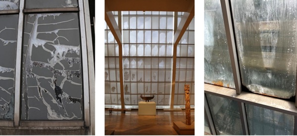
In contrast to the ABC Wings, the MCR Wing was constructed almost 100 years after Wing A and directly exposes the patrons to the building envelope. The MCR Wing was constructed in the early 1980’s as the south-facing mirror twin of the Temple of Dendur Wing on the north end of the building as part of the Roche Dinkeloo master plan. Both wings take advantage of the Met’s unique position within Central Park and feature prominent sloped glazing facades intended to maximize views and connection to the park. The northern exposure of the Temple of Dendur Wing provides diffuse natural light which works well for the primarily stone-filled gallery and allows preservation of an unobstructed view of park. However, the architectural symmetry of that geometry on the south side of the building results in exposure to harsh direct sunlight for the AAOA galleries, which are home to some of the museum’s most sensitive works of art. Daylight mitigation techniques in the form of permanently deployed roller shades and post-applied exterior films were added in attempts to control light levels, but have led to a loss of visual connection to the park as well as a host of other issues. At the time of the project’s inception, the exterior applied films had exceeded their service life, leading to large patches of exposed glazing and daylighting hotspots within the galleries. The full height roller shades were heavy and difficult to maintain, in addition to trapping a cavity of stagnant air against the glazed wall and increasing condensation issues.
Key design challenges, considerations, and opportunities for the glazing replacement at the MCR Wing included:
- Architectural requirement to maintain glazing for the full 61m (200ft) long by 18.3m (60ft) tall sloped wall in coordination with the original intent of the building’s masterplan and with Landmarks Preservation Commission (LPC) approvals.
- High solar exposure due to south-southwest orientation and 20-degree tilt of façade towards the sky.
- Stringent daylight quantity limits to maintain art conservation requirements for a wide range of objects within the same gallery and maintain future flexibility to rearrange objects within the gallery.
- Curatorial goals for daylight quality for optimal viewing experience of the artwork and clear, unobstructed views of the park.
- Curatorial goals to maintain dynamism of natural daylight levels while meeting the conservation criteria for cumulative annual light exposure for the artwork.
- Improve bird safety by providing bird-friendly glazing which limits exterior visible reflectance and reduces “fly-through risk”.
- Desire to retain the current façade load-path which is gravity supported at the base of the wall, rather than shifting to a hung or unitized system which would present load path challenges and secondary drainage obstacles.
- With a slope of 20 degrees from vertical, desire to provide post-breakage retention for overhead glazing.
- Improved thermal performance, including upgrade of sloped glazing system and improvement to triple glazing to mitigate condensation risk, including coordination with the updated mechanical systems design and energy efficiency goals. Challenge of high humidity museum set-points.
- Direct exposure of patrons to interior surface of exterior envelope.
- Desire to maintain simple and universal glazing technologies and minimize unique glazing for ease of procurement and future replacement. Specific challenge to balance views and daylight control without use of dynamic glazing technologies.
- Rigorous and cyclic coordination process between glazing design, daylighting and electric lighting design, interior casework and curatorial desires, conservation limitations, and glazing manufacturer capabilities.
- Need for high level of accuracy in optical performance measurements and assessments of glazing types.
4. Basic Performance Characteristics for Museum Glazing
Development of a baseline glazing build-up for the museum-quality daylighting control, thermal performance, and post-breakage safety required for these projects includes the same basic building blocks of most standard insulating glass units, with additional layers of refined control over the solar spectrum. Solar Heat Gain Coefficient (SHGC) and U-factor targets were slightly more flexible than the optical criteria as many coatings were able to achieve the goal of reducing these requirements below the code maximums. SHGC reduction was typically achieved by a combination of the solar control and low-E coating as well as the additional daylight mitigation treatments, and U-factor targets are typically achieved via the combination of the coating selection, argon filled cavities, and double or triple glazing.
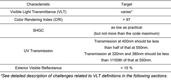
However, while SHGC and U-factor do not themselves directly impact daylight quality as they are primarily concerned with the infrared portion of the solar spectrum, the specific wavelengths that the solar control and low-E coatings filter to achieve those targets can impact the balance of the solar spectrum which is transmitted and reflected, indirectly tying them to exterior visible reflectance and transmitted Color Rendering Index (CRI). Therefore, selection of high-performance solar control and low-E coatings which maintain a CRI higher than 97, while balancing a desire for lower Visible Light Transmittance (VLT), and low exterior visible reflectance becomes an essential challenge.
Baseline performance for these case study examples also included reduced UV transmission with stringent relative reductions for longer wavelengths. However, the basic structural requirements of the PVB and/or ionoplast interlayers in addition to the other layers of glazing, coatings, and surface treatments were able to meet this criterion without need for specialty products dedicated to UV transmission reduction.
Table 1: General Daylighting Performance Characteristics and Targets.
For both projects, the inclusion of a laminated inner lite also served to satisfy structural design requirements related to overhead glazing including post-breakage retention of the glass. At the ABC Wings, the skylight glass is subject to 80psf long duration snow loading in addition to 300lb point loading for access and maintenance. While snow loads are not applicable to the MCR Wing, the incline of 20 degrees does trigger the definition of “overhead glazing” and a higher performance standard for post-breakage retention to mitigate risk of personal injury or damage to artwork. In both instances, the inner-most laminated lite was designed to a probability of breakage of 1 in 1000 for typical load cases, as well as an assessment of 70% of the maximum snow load or maintenance load applied to the inner laminate alone.
Additional general considerations which were of particular interest and priority for the Met included a desire to use globally available, industry standard components which could be competitively procured, and limit (or eliminate) operable components which would require maintenance or cleaning. The full range of daylight management strategies and technologies were investigated in the early design phases, but ultimately, the simplicity of relying on the low-E coating, surface frits / treatments, and finetuned layering of translucent interlayers proved to offer the technically simplest means of addressing the performance challenges.
5. Considerations for Visible Light Transmittance
The definition of VLT targets for museum glazing cannot be simplified to rules of thumb nor isolated from the specific considerations of each project. For both projects in this case study, VLT targets were derived via comprehensive and continuous coordination with the Met’s curatorial and conservation departments, Arup’s daylighting, electric lighting, and façade engineering consultants, the exhibit designer and architect. Rather than approaching the challenge from the exterior and working inward, the VLT and diffusion requirements for each area of glazing became a direct projection of the needs of the artwork outward onto the building envelope. Based on a refined balance of conservation requirements for each artwork’s annual cumulative lux-hr exposure limits, the curatorial goals for optimal patron experience and viewing of the artwork, the geometry and solar exposure of each gallery, and/or the distribution or orientation of each object within the gallery, Arup’s lighting consultants developed analysis models to distil the target optical performance for the glazing at various locations.
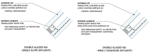
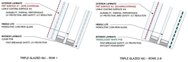
For the ABC Wings, the variation in roof geometry and resulting solar exposure between the wings was largely accommodated by the inclusion of seasonally adjustable louvers within the attic space, with each sloped skylight of each wing tuned to its optimal installation angle and adjustable seasonal openness settings. However, at Wing C where access and maintenance limitations precluded the inclusion of adjustable louvers, the glazing build-up was adapted to reduce VLT and increase diffusion with the addition of a uniform translucent frit. This particular surface treatment reduced the VLT from 50% for the typical “single slope” skylight areas to 35% at the Wing C “doghouse” skylights, and increased the uniformity of the diffusion.
For the MCR Wing, variation in VLT targets were largely focused on a desire to prioritize a ground level “view zone” to maximize visual connection to Central Park, define a targeted “daylight zone” for the rows of glass which would have a notable impact on the daylight quantity and quality in both during high summer sun angles and deeper into the gallery during winter months, and further define a “limited daylight zone” at upper rows where the majority of sun angles would be blocked by an interior mezzanine. To blend the transitions seamlessly between VLT targets for each discrete row of glass without a “striped” effect, Arup developed a custom non-uniform gradient frit pattern for Rows 2-8. These custom fit patterns were calibrated in accordance with the selected manufacturer’s capabilities and tolerances, accounting for the actual transmission through the “opaque” frit, limitations on minimum line thickness between holes, minimum diameter required for clear holes, and maximized circle packing to minimize the pattern appearance.
To maintain maximum visual transparency and views of the park through Row 1, the selection of a lowE coating that optimizes reduction of VLT while maintaining all other performance criteria was particularly challenging as many coatings achieve a low VLT and high CRI by increasing exterior visible reflectance, which negatively affects bird safety performance. This was a critical consideration for the MCR Wing due to its prominence within Central Park. Even with an exterior visible reflectance below the 15% threshold, qualitative review of glazing samples by the American Bird Conservancy at the 20 degree incline towards the sky resulted in a need to move the frit for Row 1 to surface #1 to improve the visual deterrent effect of the frit pattern. Ultimately, GlasTroesch’s CombiSilver 32/21 T provided the most successful balance of all performance criteria and avoided excessive Row 1 frit coverage and/or the addition of tinted substrates to further reduce VLT and achieve the 20% target.
6. Challenges Related to Diffuse Glazing
The process of refining a glazing build-up for daylighting applications is often strained by the accuracy of VLT estimates for highly diffusing products. In particular, when layering multiple diffusing elements within the thickness of a build-up. It is well documented that industry standard integrating spheres used to measure the optical properties of transparent or specular glazing materials underestimate (sometimes dramatically) the total VLT of diffusing materials. Therefore, relying on calculated estimates or manufacturer data can create a risk that conservation levels will not be achieved in the final construction.
In some cases, the accuracy requirements may be less sensitive if there are additional measures of dynamic adjustment (e.g. inclusion of roller shades, operable louvers, interior partitions, etc.) or if the artwork’s conservation criteria allow for a wider range of exposure levels. For example, at the single slope skylights of the Met’s A and B Wings, there was the ability to make slight adjustments to the ouver positions if the accurate measurements of the final samples showed minor discrepancies from the estimated or calculated performance. However, a reasonable correlation between the estimates used in the lighting simulations and the realistic VLT was still necessary to avoid unexpected costs and change orders for the louver perforation. Additionally, a more accurate understanding of the glazing VLT and diffusion properties allowed the design team to maximize the openness of the louver positions throughout the year to increase the “liveliness” of the light quality. With the original manufacturer data underestimating the VLT by 20-30% the ability to make seasonal adjustments at the louver level would have been heavily limited, resulting in a deadened daylight quality with the louvers mostly closed for the majority of the year.
In contrast, at the Wing C doghouses and the MCR Wing sloped glazing, confirming the accuracy of the estimated / calculated values prior to fabrication and installation was substantially more sensitive as there was no recourse to make even small adjustments after construction. Ultimately, given the sensitivity of the projects as well as the desire to compare multiple products and options, Arup developed a workflow to transition from digital models to final glazing build-ups including the following steps:
a. Vet table-top samples with the support of manufacturer data and in-house informal measurements.
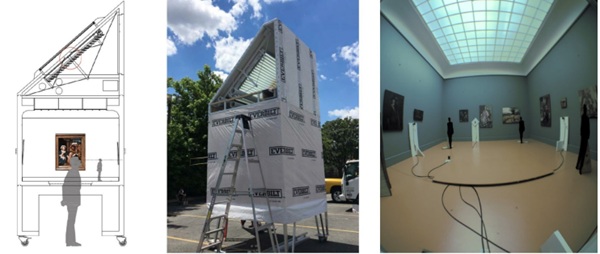
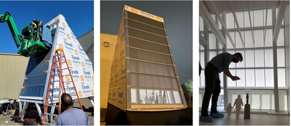
b. Short-list samples to be included in a ¼ scale daylighting mock-up, allowing physical measurement of the light levels within a replicated gallery setting and review of light quality considerations with the architects and owner.
c. Select build-ups for physical testing using goniophotometer (or a large diameter integrating sphere) as final validation and record, to become the basis for the material order.
For both case study projects, the daylighting mock-up served multiple valuable purposes, allowing for stakeholder review and engagement, assessing the interconnected performance impacts of multiple layers of glazing and shading, long duration data gathering and viewing opportunities under varying weather conditions and sun angles, narrowing down material options, assessing a trial run of larger scale units from a production line rather than a sample line (applicable to some manufacturers), etc.
In both projects, the final stage of validation including physical testing of samples provided fine-tuning of the final daylighting models and valuable owner records of performance if long term future glazing replacement is required. For the ABC Wings project the use of goniophotometer characterization of the glass build-ups not only provided accurate total VLT, it also identified the presence of a small component of specular transmission through the translucent interlayer. This was counteracted by the addition of the diffusing frit at Wing C and adjustable louvers at the typical sloped skylights. For the MCR Wing, the diffusion of the nearly opaque interlayer was more reliably understood, so large diameter integrating sphere measurements were sufficient to confirm the optical performance of the glazing build-ups, including the effects of the manufacturer’s specific gray ceramic frit.
7. Weather and Structural Performance Validation
Further to the daylight quality and quantity management, and the performance requirements related to thermal control and condensation resistance, the weather and structural performance of skylight and sloped glazing systems shared equal importance as components of the infrastructural upgrades to the building. Performance mock-up testing and field quality control testing were both utilized to validate detailing and glazing performance.
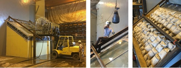
Performance mock-up testing for the ABC Wings skylight system included structural wind load testing, air and water infiltration testing under static pressure differential, water infiltration testing under dynamic pressure. In addition to the standard battery of weather and structural testing, atypical testing to address the project’s specific requirements and client considerations included impact testing for access and maintenance and long-duration snow load testing. As American test standards to not provide unique guidance for overhead glazing or skylights, the Centre for Window and Cladding Technology (CWCT) Technical Note 67 was used as a reference to test breakage resistance and post-breakage retention for access and maintenance loads. A custom 30-day duration sandbag test was also undertaken to assess performance and interlayer creep under the large snow loads.
8. Conclusions
Glazing design for the purpose of museum daylighting presents a unique challenge, particularly when further constrained by the context of historic building renovation. The design and validation processes require careful consideration and coordination of the project site, context, climate, art, architecture, experiential goals, structure, and building physics. The ultimate goal is to achieve a deceivingly simple and efficient glazing build-up that itself goes largely unnoticed, yet minimizes maintenance and consumption for the owner, creates an optimal environment for the artwork it protects, and maximizes the enjoyment of the patrons.
Acknowledgements
As with all major construction projects, the successes of these renovations are credited to the dedication of large groups of collaborators, beginning with the initial concept and continuing through construction. The owner, design teams, and construction partners all played critical roles in the success of both projects.
Key players for the European Paintings / ABC Wings Renovation included the Metropolitan Museum of Art (Owner), Beyer Blinder Belle Architects and Planners (Executive Architect), Arup (Façade Engineering & Building Physics Consultant, Lighting Consultant, and Structural Engineer), Wiss Janney Elstner Associates (Roofing Consultant), Kohler Ronan (Mechanical Engineer), Skanska (Construction Manager), LINEL (Skylight Manufacturer), Tri-State Skylights (Installer).
Key players for the AAOA / Michael C Rockefeller Wing Renovation included the Metropolitan Museum of Art (Owner), Beyer Blinder Belle Architects and Planners (Executive Architect), WHY Architecture (Exhibition Designer), Arup (Façade Engineering & Building Physics Consultant, Daylighting & Exhibit Lighting Consultant), Kohler Ronan (Mechanical Engineer), Wiss Janney Elstner Associates (Opaque Envelope Consultant), AECOM Tishman (Construction Manager), LINEL (System Manufacturer), W&W Glass and Atlantech Systems (Installers).


Comments
Who knew the real hero of museum experience isn’t just lighting or architecture, but glass doing a full balancing act between preserving art, blocking heat, and still letting the sky feel present… invisible work, massive impact.