This paper was first presented at GPD 2025.
Link to the full GPD 2025 conference book: GPD_2025_ConferenceProceedingsBook.pdf

Author: Mikko Rantala - Glaston Finland Oy
Abstract
The clear disadvantage of air jet quenching is the need for high electric power when thin glass (thickness 4 mm and below) is processed, which also entails significant energy consumption. The total input power of fans in a glass tempering chiller can be as much as one megawatt. Attempts have been made to solve this problem of thin glass thermal tempering in many ways during the last 50 years. Many patent applications have been written which have attempted to arrange cooling with a water mist, contact heat transfer, and carbon dioxide snow, for example. Despite a wide range of ideas, quenching in today’s world is arranged with air jets. The paper introduces the above efforts to challenge air jet quenching and considers their possibilities. For the most part, the paper focuses on reducing the energy consumption of air jet tempering. It highlights clear possibilities or even solutions that exist on the market to reduce energy consumption in glass air jet quenching. Reducing energy consumption also reduces operating costs and CO2 emissions. The paper aims to state that some opportunities for energy saving are relatively simple, and their payback period may also be attractive. However, in many cases, the additional cost of such opportunities is still a problem for their sale.
Article Information
- Published by Glass Performance Days, on behalf of the author(s)
- Published as part of the Glass Performance Days Conference Proceedings, June 2025
- Editors: Jan Belis, Christian Louter & Marko Mökkönen
- This work is licensed under a Creative Commons Attribution 4.0 International (CC BY 4.0) license.
- Copyright © 2025 with the author(s)
1. Introduction
Glass tempering is a process in which glass is first heated to a tempering temperature (above 600 ˚C) and then cooled rapidly with air jets. This creates residual stresses inside the glass which makes it stronger, and it breaks into the sort of crumbs that fulfill the requirements of safety glass standards.
The compression stress established in tempering on the glass surface (degree of strength of tempering) depends on the temperature profile of glass in the thickness direction, as the glass cools through a transition temperature range (about 600→500˚ C) typical for soda lime silica glass. Thinner glass requires more cooling effect to obtain the same temperature profile. For example, the tempering of 3 mm thick glass requires approximately five times more cooling fan motor power per glass area than the tempering of 4 mm thick glass.
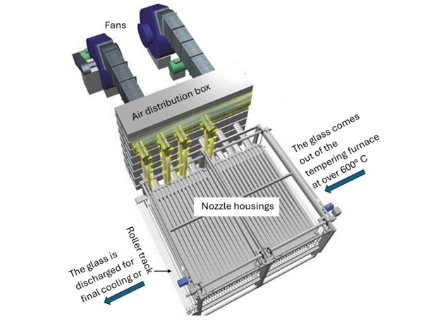
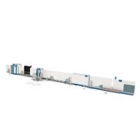
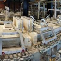
The glass tempering quench device consists of fans air supply ducts and fan housings as Figure 1 shows. The glasses travel on a roller track between the upper and lower nozzle housings equipped with plurality of rows consisting of drilled holes, from which air jets are discharged towards the glass. There are dozens of nozzle housings in a row with a pitch of 80 to 140 mm. The length of the nozzle housing, i.e. the width of the blowing area, can be up to 3.3 m. Such air jet tempering method is an almost perfect tempering cooling technique for glasses with a thickness of at least 5 mm, but it can be said that the fan motor power required for tempering cooling, and the energy consumption consumed by the fans, start to become a problem when tempering glasses at most 4 mm thick. For example, the energy consumption in a tempering cooling of 3 mm glass is about 1.5 kWh per glass square meter, depending on the quench type, production capacity and loading degree, and the total input power for the fan motors of a quench can easily be one megawatt.
Attempts have been made to solve this problem of thin glass thermal tempering in many ways during the last 50 years. The paper introduces efforts to challenge air jet quenching and considers their possibilities. For the most part, the paper focuses on reducing the energy consumption of air jet tempering.
2. Industry efforts to challenge glass air jet quenching
2.1. Tempering cooling by water spray
Water mist cooling can be divided into two main technologies. In the first, water is fed into a compressed airflow, which creates water droplets in the air jet released from the nozzle (pneumatic method). In the second, droplets are formed by feeding water under very high pressure into a nozzle with a small opening (hydraulic method).
The pneumatic method has been used to enhance the tempering cooling of glass in several studies. The process was patented by Saint-Gobain through a patent (1986). The company cancelled the patent eight years later. It should be mentioned that as early as 1936, the Pilkington Brothers (GB441017) proposed the use of a two-phase nozzle for tempering glass.
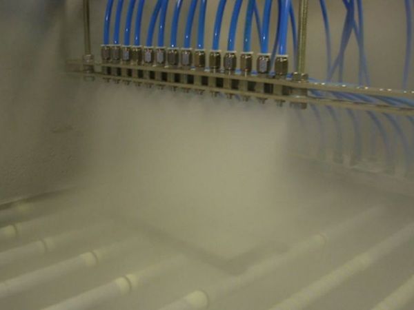
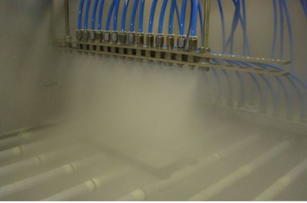
An appropriately sized water droplet (10–30 μm) and a dense and even distribution of water droplets in the air jet are essential for the mist cooling of glass. There are many different types of nozzles on the market, which vary in droplet size and spray shape. Both compressed air and water are supplied to the nozzle, and by changing the pressure of the compressed air, the size of the mist droplets and the shape of the spray can be changed to a limited extent. Increasing the pressure of the compressed air also increases the velocity of the droplets, which also affects the cooling effect they create on the surface of the glass. Figure 2 shows an attempt to temper the glass with such two-phase nozzles.
There are several scientific publications on similar laboratory studies. In (Sozbir & Yao, 2017) small pieces of glass were vertically held by a hanger during water mist tempering. Some glasses were tempered successfully, but the tempering was far from easy and unfailing, which is not promising for the true-scale production of tempered glass. With air jets, glass breakage during tempering is very rare, as long as the glass is sufficiently warm for tempering. As the share of waste glass increases, the energy savings of tempering cooling disappear quite quickly, as the heating energy they bind from the tempering furnace is also a loss. When the entire glass production chain is also considered, from the extraction of raw materials to flat glass, a low percentage of waste in the tempering process is important for sustainability.
However, in the publications’ conclusions, it is often stated that water mist cooling is an effective method for thin glass tempering cooling. It is impossible to agree with this opinion when a real-scale production line is taken as an application. First, the boost that water droplets give to the cooling capacity can be considered a significant disappointment due to the so-called Leidenfrost effect. In this phenomenon, a drop of water on a hot surface vaporizes, forming an insulating layer of vapor between the surface and the droplet. In (Sozbir & Yao, 2017), a significant increase in cooling capacity was obtained by adding water droplets to a compressed air jet. However, at clear boost to cooling power would have been achieved by simply moving the compressed air nozzle closer to the glass, i.e., from 40 to 15 mm, which is a typical blowing distance in glass tempering quenches. Of course, the same can be done with a mist nozzle, but this leads to the multiplication of mist nozzles to achieve a sufficiently uniform cooling effect. A glass tempering quench consists of a few thousand nozzles, which in air jet tempering are just holes drilled into the blowing housing. A malfunction of even one mist nozzle or condensation of moisture into a bigger droplet falling on glass surface would ruin the entire tempering process. Tempering of glass in a vertical position, e.g. to reduce this problem, is out of the question in a real-scale glass tempering line.
It should also be noted that pneumatic water mist nozzles consume a significant amount of compressed air and are quite costly. Hydraulic water mist nozzles eliminate these two problems but increase the risk of large water droplets falling on the top of the glass. Kim & Jeon (2023) use hydraulically formed water droplets for glass tempering in addition to separate air jets. In its photographs, the change in glass breakage patterns achieved by adding water droplets to cooling is negligible. This also applies to measured glass surface residual stresses.
One problem is that when the mist jet hits a glass-free area (e.g., a roller) in a quench, it moistens it, which is a risk for the tempering of the next glass arriving in this area.
2.2. Tempering of a glass by contact
In contact tempering, the glass’s cooling is implemented or enhanced by bringing the cold flat surface into contact with the glass. In this case, the heat from the glass is transferred by conduction to the flat surface.
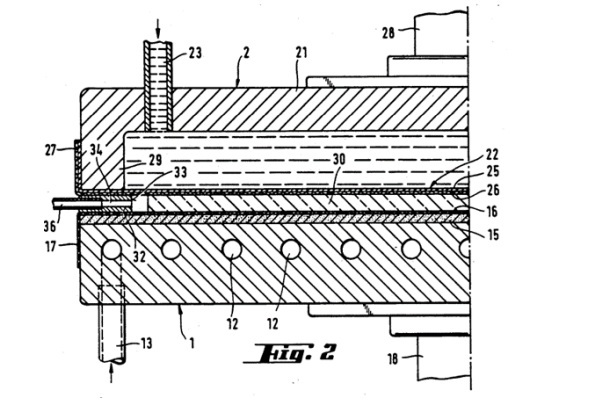
The glass tempering device in Figure 3 has two water-circuit-cooled compression plates (1,2) between which the glass (30) can be held. On the top, cooling water flows above a flexible membrane (22), including thin polytetrafluoroethylene film which is covered on its outer surface by a metal gauze (26) that is in contact with the glass. On the bottom, the cooling plate’s compression surface is provided by a layer (15) of an elastically deformable material. A metallic cooling plate with good thermal conductivity is cooled by water circuit pipes (12) inside it.
Patent application US2011/0271716A1 (2011) describes laboratory tests in which 2 and 4 mm thick glass plates (100 x 100 mm) heated to at least 700 °C were quickly moved between two 80–90 °C steel cooling plates. The fracture patterns obtained were significantly better than required by the DIN 12150 standard. The stress-deformation figure (anisotropy) was bad. As a production implementation method for transferring glass to contact tempering, the publication proposes a belt conveyor for moving a glass to between two cooling plates after which the cooling plates are moved to contact with the glass.
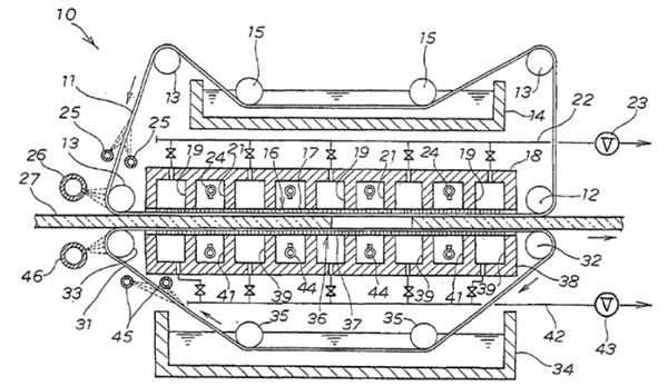
Contact-tempering enables a strong cooling effect. However, utilizing it on a large scale seems to be a very problematic device in design work. The belt conveyor is in reality very difficult to implement so that it can keep the glasses straight and does not interfere with the cooling of the glass. In addition, the entire glass or glass loading must be completely between the cooling plates before they can touch the glass. During this transfer time, the front end of the thin glass has time to cool down. The device in Figure 4 solves these problems by guiding a glass between the two wet belt conveyors that carry out contact tempering. In the picture, devices 14, 24, 25, 26, 34, 44, 45, and 46 are belt humidifiers. The upper and lower water tanks (14, 34) also have the function of cooling the upper and lower belts. The invention is interesting, even though there was an obstacle to its patentability. However, it should be taken into account that touching the glass exposes it to scratches, and it is difficult to implement the touching completely simultaneously and evenly on large glass surfaces.
2.3. Tempering cooling of glass with the help of gas thermal conductivity
One of the latest ideas for implementing tempering cooling in glass is to transfer heat away from the glass using the thermal conductivity of the gas (Corning Inc., 2016). The glass (200) in Figure 5 is guided into a narrow gap (240) between the two heat sinks (201a, 202a). The glass does not touch the heat sinks, but there is a very narrow gap S (204a, 204b) between it and the glass, with a thickness of about 0.1 mm.
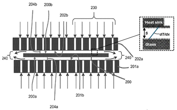
The goal is that the gas in the gap acts as a solid material, so that the heat flow Q across the gas gap can be calculated from the equation, Q = (k/S)ΔT, where k is the thermal conductivity of gas, and ΔT is the temperature difference between the glass and heat sink surfaces. In this case, the cooling capacity can become very high, as the gap’s thickness is very small. When using air as a gas, the gas gap should only be a maximum of 0.05 mm to theoretically achieve the same heat transfer coefficient (h=k/S) level (≈ 1000 Wm-2K-1) as in the most powerful air jet tempering quenches of glass today with which 2 mm glass can be tempered as a safety glass. For 4 mm glass the corresponding gas gap thickness S is about 0.1 mm.
In the device, the heat conducted from the glass over the gas gap to the heat sink is transferred away by a cooling circuit arranged in the heat sink. Heat transfer gas is fed into the gap through holes in the heat sink. The publication gives many examples in which helium is used in the gas gap and promises a compression stress of more than 200 MPa on the surface of the 0.7 mm thick soda-lime glass. It is impossible to know whether these are just theoretical calculations, or whether the glass is actually tempered.
The problem here may be that the gas does not behave as desired. For heat to be conducted in a gas as in a solid, it would require that when the glass enters between the heat sinks, a linear temperature profile (dT/dx) would form very quickly in the gas. Conduction does not occur at all if the temperature profile of the gas has the zero point of the derivative. The gas must therefore not swirl at all.
It is probably impossible to apply the invention on a large scale in the tempering of solar or architectural glass. An insurmountable problem would be that soda-lime glass bends easily when the heating power on different sides of the glass differs, but it should not bend at all between the cooling plates. Furthermore, very small dimensional tolerances on a large scale would make the device impossible— or at least very expensive.
2.4. Other ideas to challenge pure air jet tempering
There are many different inventions for tempering glass. In US3929442 (PPG Industries Inc., 1975) it is proposed to use air containing soft particles of solid sublimate materials like carbon dioxide snow for glass tempering. Patent application GB441017 develops water mist tempering by applying water droplets at 100 ˚ C or wet steam to the glass surface, which evaporates there more easily than cold droplets. W02013102702A1 proposes placing a wet porous membrane near the glass, and liquid material is removed from the membrane by a blast of air to form liquid droplets into air jets hitting the glass to be tempered.
3. Possibilities reduce energy consumption in glass air jet quenching
The above efforts to achieve a strong cooling effect on the glass surface do not seem to have much potential in the effort to reduce the energy consumption of glass tempering cooling, especially where the production of (soda-lime-silica) glass with a size of at least 1 x 1 m and/or tempering of glass loadings consisting of multiple glasses are concerned.
Next, some opportunities for energy savings in air jet quenching are introduced.
3.1. Optimizing glass loads
The energy consumption per square of tempered glass decreases as the loading rate of the tempering line increases because glass tempering losses are mainly independent of the loading size. Today, this advantage is quite topical due to the new automatic glass loading assembly systems on the market (Glaston Finland Oy, 2024). The idea is to use information about the required production (e.g., glass size, thickness, number) and the glasses in stock, and let the computer algorithm optimize the loading rate. This is an indirect means of reducing energy consumption in quenching. The following means are direct—i.e., they aim to reduce the momentary electric power usage in quenching.
3.2. Elimination of unnecessary blowing along the width and length of the quench
Generally, glass tempering cooling blowing covers the entire width of the quench, even if the width of the glass loading is significantly lower. Blowing on a glass-free area can be treated as a loss. This loss can be reduced by attempting to temper the fullest possible glass loads. To reduce the problem, it is also possible to use devices that narrow the blowing width.
In Figure 6, the narrowing of the blowing width is implemented with a sliding perforated plate (10) inside the other end of the nozzle housing. In this case, the blow holes (6) can be opened and closed by moving the perforated plate in the direction of the nozzle housing.
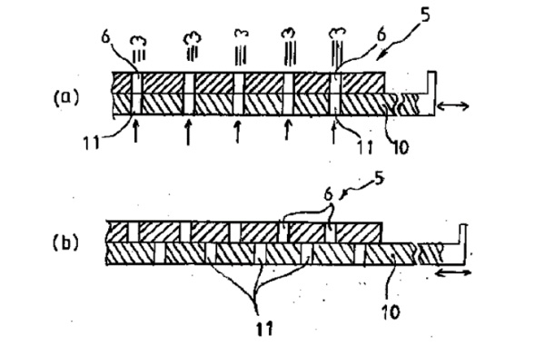
In Figure 7, the nozzle housing is equipped with two butterfly valves (5a, 5b) with which blowing to the end part of the nozzle housing can be prevented.
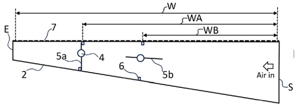
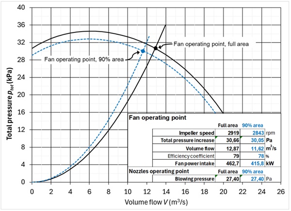
The control method for both devices above is the same. If the sensors detecting the width of the glass loading find that the glass loading does not reach the width controlled by the perforated plate or butterfly valve, blowing to this length is prevented. To operate the equipment efficiently, it is important that the glass loading is assembled beginning from the very first edge of the loading table, so that there is usually enough empty space on the second edge to close the blow openings at the end of the nozzle housings. This closing not only reduces the volumetric flow generated by the fan but also allows a slight reduction in the impeller speed to achieve the same blowing pressure. Figure 8 shows how the fan’s operating point changes in more detail. The picture corresponds to the moment of 3 mm tempering of glass in a quench with a full blowing width of 2.1 m, of which 10% is closed with the above-mentioned method. In the example, the fan motor power intake decreases from 462.7 to 415.8 kW. It therefore decreases by 47 kW—very nearly 10%.
The electrical energy saved by the method in a year depends not only on the quantity and quality of annual production but also on how often the loading width allows it to close part of the blowing width.
In practice, the length of the quenching area increases with the thickness of the glass, which also increases the fan motor power. One way to save energy is to equip the tempering air distribution box (see Figure 1) with valves that can be used to shorten the length of the tempering area when glass thickness gets smaller. On the other hand, by closing such a valve, the blowing pressure in the tempering area can also be increased (Uniglass Engineering Oy., 2001). In glass tempering units, where a glass loading moves back and forth in a cooling area during cooling, the length of the cooling area can be shortened with corresponding valves, if the loading length allows. The energy savings achieved by shortening and narrowing the blowing area are calculated using the same principle. The relative reduction in fan motor power corresponds to the relative reduction in the blowing area.
3.3. Carbon impeller in a fan
According to fan manufacturers, compared to a normal steel impeller, a carbon impeller offers significant energy savings for cyclic processes. The benefit is based on the durability and lightness of the carbon impeller, which allows a significantly deeper reduction in impeller rpm during short breaks in cyclic production. Figure 8 illustrates the difference between operating a carbon impeller and a steel impeller in the batch type tempering process of 4 mm glass.
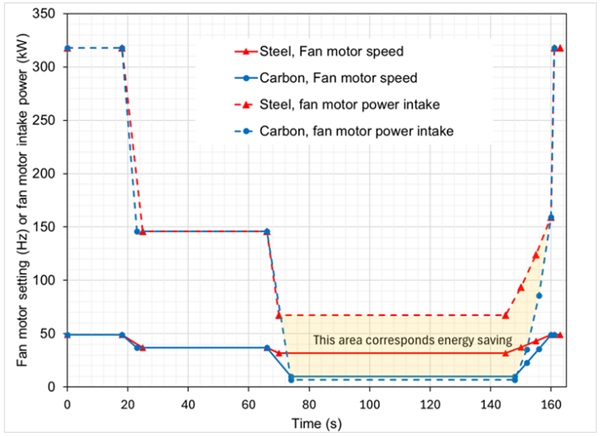
The curves in Figure 9 begin with tempering cooling, when the impeller speed is at its maximum. This step lasts about 20 seconds per glass load. After tempering, the glass loading remains oscillating in the quench, and the cooling phase begins. The main difference between the operation of a steel and a carbon impeller starts when the glass cools down sufficiently, which is when the idle phase begins (67 s in the figure). Decelerating and accelerating the rotational speed of a steel impeller during the glass tempering cycle is much more limited than that of a carbon impeller for durability reasons. In Figure 8, the rpm of a carbon impeller is reduced to 10 Hz at idle compared to 32 Hz for a steel one. The area between the fan motor power curves corresponds to the difference in energy consumption, which is 1.4 kWh per glass load. This corresponds to a reduction in electricity consumption of about 25%.
3.4. Cooling of air used in quench
The instantaneous power of convection cooling can be calculated simply by multiplying the convective heat transfer coefficient by the temperature difference between the glass surface and the cooling air. Reducing the temperature of the cooling air increases the cooling capacity, meaning the convective heat transfer coefficient can be reduced, i.e., the speed of the fan impeller can be reduced to achieve the same tempering result. In this case, the electrical power drawn by the fan motor decreases.
The fan raises the air temperature by about 1 °C per 1 kPa of total pressure increase. The temperature rises mainly due to the increase in pressure, but also slightly as the losses of the fan turn into heat. The potential of air cooling to reduce energy consumption thus increases as the blowing pressure required for tempering increases. For example, when tempering 3 mm glass, the air temperature typically rises from 20 to 45 °C. This temperature difference in the temperature of the discharged air jets already has a significant impact on the required blowing pressure. It is unrealistic to re-cool the air close to the ambient temperature. For example, a drop of 10 °C in the effective temperature of the air jets during the moments of tempering cooling allows a reduction of about 2% in the convective heat transfer coefficient. This corresponds to a 6% reduction in the blowing pressure and a further 9% reduction in the electrical power taken by a fan motor.
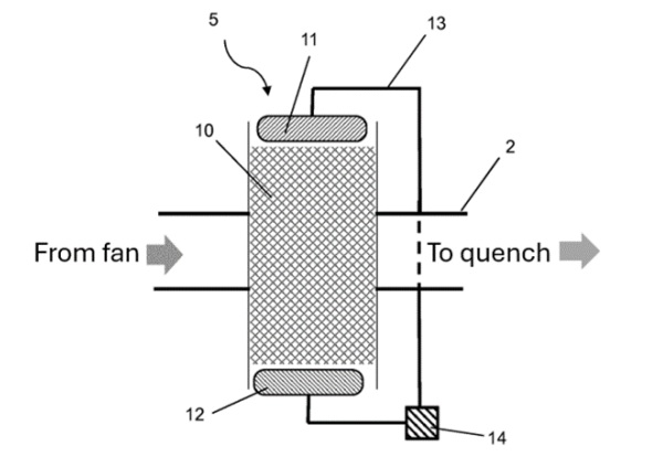
At least the following options have been proposed for cooling the air. Adiabatic cooling of air refers to increasing its relative humidity by bringing air into contact with water. The relative humidity in the pressure duct after the fan decreases by the above-mentioned temperature increase, which means that the cooling potential of this technology also increases when the blowing pressure requirement increases, i.e., as the tempered glass thins. In (Saint-Gobain Glass, 2020), adiabatic cooling is implemented by adding the wet honeycomb (10) to the air feeding duct, as shown in Figure 10. As air flows through the wet honeycomb, its relative humidity increases, causing it to automatically cool down.
The problem with adiabatic cooling is that when the pressure is released after the cooling air jets are discharged, the air re-cools to the ambient temperature, and because moisture has been added to it, its relative humidity rises above 100%. In this case, moisture begins to condense into water droplets even on the surfaces of the nozzle housings, which causes problems for successful tempering. Moisture problems also apply to the factory hall, where the humid and warm air leaving the glass quench also creates an uncomfortable environment. The investments required to overcome these problems significantly increase the cost of the equipment.
Cooling the air with electric chillers containing refrigerants does not save energy, because usually the electrical power they use would exceed the reduction in power taken by the tempering fan.
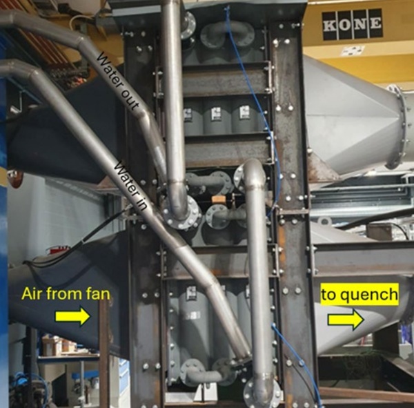
Finally, the technology with the most potential for cooling the air involves adding a normal heat exchanger to the pressure duct, where the air to be cooled flows between the fins cooled by the water circuit. Figure 11 shows such a device in the air supply duct. In such a system, the electricity consumed by the additional equipment required (a pump and a cooling tower fan) is low, and the pressure drop in the supply airflow caused by the heat exchanger can be made quite small.
3.5. Design of glass tempering cooling system
From the energy consumption perspective, it is particularly important that the tempering cooling system with fans, air supply ducts, and nozzle housings has been designed with this in mind.
Pre-planning for sales quotations begins with calculating how much tempering pressure is needed to meet customer requirements (the thinnest temperable glass) in the conditions of the factory location. The significant oversizing of the tempering fans leads to a higher asking price due to the rising price of the fan and electrical equipment it needs. Meanwhile, significant undersizing easily leads to problems and expensive backorders later. However, the only factor affecting energy consumption in fan sizing is that the fan’s good efficiency range coincides with the tempering process’s operating points. In this respect, the sizing is unlikely to completely fail. Despite this, more accurate dimensioning brings up to 3% continuous energy savings. However, the manufacturer of a glass tempering machine often has to take commercial matters into account when choosing a quench fan. The purchase price for dozens of identical fans is significantly lower than for dozens of fans tailored for different processes. In some cases, the sale of a customized fan as an additional option would allow further energy consumption savings.
Pressure losses in the blowing ducts are a significant addition to energy consumption. It is particularly important to design the ducts to avoid additional pressure losses. In this respect, the design is often at least quite successful, yet further development brings 2 to 5% energy savings if practical obstacles do not significantly limit the space allowed for air ducts.
The current blowing housings with their nozzle systems are already quite optimized in terms of energy consumption. However, sufficient convection uniformity is also an important criterion in their design so that the impact of air jets on the tempered glass does not form a residual stress pattern (anisotropy) that disturbs the eye. However, it is obvious that with the development of the nozzle system, it remains possible to achieve energy consumption savings of at least a few percent.
More precise control of tempering cooling is one option with energy-saving potential. For example, savings are made by not tempering the glass to an unnecessarily high residual stress in relation to the requirements of safety glass standards. Inventions such as (Glaston Finland Oy, 2021) help with this.
4. Conclusions
In a typical batch type glass tempering line for mixed size glass production about 200 MWh of electricity is consumed per year for glass tempering cooling, which corresponded 48 tons of CO2 emissions in the EU in 2023 when average emission factor for electricity was 242 g/kWh. The energy consumption increases as production and the size of the tempering line increase, and when the average thickness of the glass decreases. In a continuous type high-capacity solar energy glass tempering line, the consumption is tens of times higher.
In conclusion, this energy consumption can be significantly reduced if one is willing to invest in existing energy saving opportunities of air jet tempering, most of which were introduced in this paper. There is no need to expect any new and revolutionary glass tempering cooling technology to replace air jet cooling. The possibilities of the technologies that challenge air jet tempering highlighted in the paper seem small, at least in large-scale solar and architectural glass tempering.
Based on the opinion of sales experts in the field, the purchase price of a glass tempering line remains a significantly more important factor than energy consumption savings in CO2 emissions and electricity bills that can be achieved with additional investment. The glass tempering machine manufacturer cannot therefore add cost-increasing energy-saving modifications or equipment to its product’s basic configuration. In addition to reducing the energy consumption of the basic configuration of its products, the role of the glass tempering machine manufacturer in the general effort to reduce energy consumption is to bring energy-saving opportunities to its sales lists as additional products for its customers to choose from. In this case, accurate customer-specific estimates of the annual energy savings and the payback period of the additional product are necessary.
References
Central Glass Co Ltd. (2001). Patent JP2001192226. Method and device for tempering glass sheet
Corning Inc. (2016). Patent US9296638B2. Thermally tempered glass and methods and apparatuses for tempering of glass.
Glaston Finland Oy (2021).Patent application EP3858794A1. Method for tempering a glass sheet
Glaston Finland Oy (2024). video retrieved from https://www.youtube.com/watch?v=A0PpsqsDQuc
Glaston Finland Oy (2025). Patent FI131387. Device and method for cooling glass with air jets
Kim, Y. S., & Jeon, E. S. (2023). Analyzing the stress characteristics of glass as a function of cooling rate when applying air and mist for rapid cooling of glass heated to high temperatures. Thermal Science and Engineering Progress, 46.
Nippon Sheet Glass Co. Ltd. (2004). Patent application US2004/0107733A1. Method and apparatus for forcedly cooling sheets of glass and tempered sheet glass. Patent application US2011/0271716A1 (2011). Method for producing thermally tempered glasses.
Saint-Gobain Recherche (1986). Patent US4578102. Quenching or tempering by means of a two-phase jet.
Saint-Gobain Glass (2020). Patent application WO2020/052828A1. Device and method for thermally tempering glass panes with heat exchanger
Sozbir, N., & Yao, S. C. (2017). Spray mist cooling heat transfer in glass tempering process. Heat and Mass Transfer, 53 1699–1711.
Uniglass Engineering Oy. (2001). Patent US6279350B1. Adjusting cooling air in glass tempering machine
University Freiberg Bergakademie (1991). Patent US5021075. Device for tempering by contact of glazings. SaintGobain Vitrage International