First presented at GPD 2017
However, popularity should not hide the fact that this type of construction is delicate due to the intrinsic fragile nature of glass combined with the stress concentrations that appear in connections. Careful design and construction are required in order to deliver a safe and durable product to the client. Recently, the authors have been involved in a number of such structural glass projects. The aim of this paper is to show some of the connections that were employed in these projects and to discuss the techniques used for their structural analysis, design and construction.
Introduction
In the last decade there has been a growing trend in Architecture to incorporate into buildings some iconic all-glass elements, such as entrance façades, rooflights, staircases, etc. These are aimed at reaching the highest level of transparency, thus the use of any structural material other than glass is to be minimised. Despite the existance of some remarkable pioneering works in the 1990’s, such as the glass bridge in Rotterdam by Dirk Jan Postel, it was not until 2006 that this type of construction became increasingly popular thanks to the opening of the Apple store in the 5th avenue of New York with its well-known glass cube and staircase.
However, popularity should not hide the fact that this type of construction is delicate due to the stress concentrations that appear in connections that glass, being a perfectly elastic and fragile material, is unable to redistribute. These stress concentrations may be caused by either the existance of holes or notches on glass, the bonding of metal parts that create sudden stiffness changes on the panel surface, or simply by the application of a significant force on a small glass area. This results in connections most often governing the design of structural glass components.
Recently, the authors have been involved in a number of such structural glass projects, from a government building in London, to an educational building in Montpellier, an office building in Madrid and a number of retail shops around the globe. A discussion on some of the connection details and design methods employed in these projects follows.
The importance of global modelling
The previous section has emphasized the importance of connections in the design of structural glass components. But the first step in a proper design of a connection is to know with certitude the forces being applied to it. Therefore, the design of a structural glass façade should always start with the definition of a structural scheme with clear load paths that remove any ambiguity in the determination of the loads applied to each connection.
However, the complexity of modern projects often require to complement these structural schemes with sufficiently accurate numerical models with the aim of capturing any second order effects that may have skipped the initial manual calculations or to take into account the load transfer between adjacent glass panels through structural silicone joints, etc.
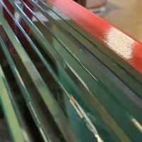
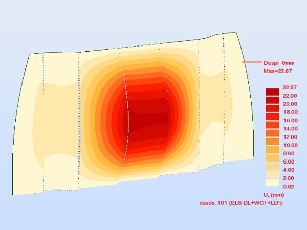
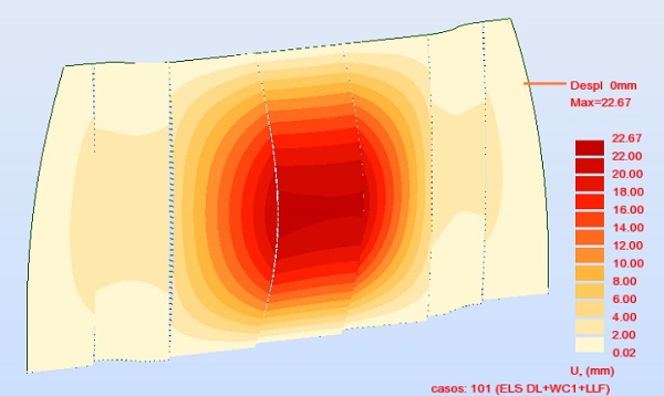
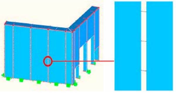
As a simple example of the latter, fig.1 shows the use of structural silicone joints to reduce the wind deflection of the central two-side supported flat glass panels (measuring 2.5 x 8.0 m approx.) by transferring part of the wind load to the side panels which have a significatly higher bending stiffness due to their curvature. In this case, the flat glass panels were able to resist the factored wind load alone, but the deflection requirements in service could only be met by considering the façade to behave (partially) as a single panel.
Structural silicone modelling and design
The projects that led to the publication of this paper made extensive use of structural silicone bonds for three different functions:
a) To make compatible the out-of-plane deflection of adjacent glass panels under wind load, as shown in fig.1.
b) To provide cross-bracing in the plane of the façade, specially in glass pavillions where two glass façades are connected at an angle, or where the façade is subject to in-plane seismic loads.
c) To avoid the distortion of the façade under small relative displacements of the supporting structure.
In order to properly capture the stresses and strains in each structural silicone joint of a façade, these are included in the global structural model by means of a series of beam elements connecting the glass panels together at constant distances in the range of 100-200 mm (fig.2).
The stiffness of each silicone joint is to be studied by means of finite element models that take into account the actual geometry of the bond and the nonlinear behaviour of the specific silicone product for the range of strains under consideration.
The reader is warned against using certain silicone stiffnesses published by silicone manufacturers which may correspond to tensile tests on dumbell specimens or to joints with aspect ratios of about 1:2, typically found in curtain walling applications. Deeper joints may show significatly higher stiffnesses, specially in tension and compression, and possibly higher stresses than those expected if the above values were used.
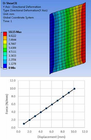
In the projects mentioned above, twodimensional plane strain finite element analyses were performed for each joint geometry considering the hyperelastic material model of the sealant, which was supplied by the silicone manufacturer. Tension, compression and out-of-plane shear were analysed at different levels of stress within the acceptable range. The stiffness of the joint under in-plane shear was assumed to be similar to that of out-of-plane shear
Figure 3 shows the results of such analysis for a 50x30mm joint subject to out-of-plane shear. Note that the response in the considered range of forces/displacements is almost perfectly linear, thus a single value of effective shear modulus could be found. Linearity was slightly worse in tension and compression.
The design strength of a structural silicone bond may be obtained from the European Technical Assessment (ETA) of the product. However, the values shown in the ETA are normally affected by a safety coefficient of 6 that is intended to be used in combination with the simplified methods of analysis shown in ETAG 002 [1]. For more accurate analysis methods such as the one discussed in this paper, the use of lower safety coefficients is possible. Dow Corning recommends a safety coefficient of 4 in this situation [2].
Finally, it is necessary to take into account the interaction of axial and shear stresses in order to obtain a design method that can be applied in practice. Back in 1989 Sandberg and Ahlborn [3] suggested an elliptical interaction for silicone joints under short-term loads. Currently, silicone manufacturers can provide slightly modified expressions that improve the accuracy of the former and take into account the concurrent application of short- and longterm loads.
Stiffness of the supporting structure
Sometimes the deformation expected in the building structure to which a façade is connected may not be compatible with the façade design, creating excessive stresses in glass joints or even collissions between panels. This was the case of an entrance hall to an office building in Madrid, in which two structural glass façades made up of laminated glass panels with a typical size of 3.0 x 10.0 m (b x h) were to be installed on a hybrid steel and concrete slab built in the 1980’s.
Obviously, the supporting slab had to be reinforced to meet the new loading conditions and to provide a sufficiently stiff base for the new glass façade. In spite of the reinforcement, the façade showed to be highly sensitive to deformations at the base, which created excessive stresses in the vertical structural silicone joints and detachment of some glass panels from one of their support pads in some circumstances.
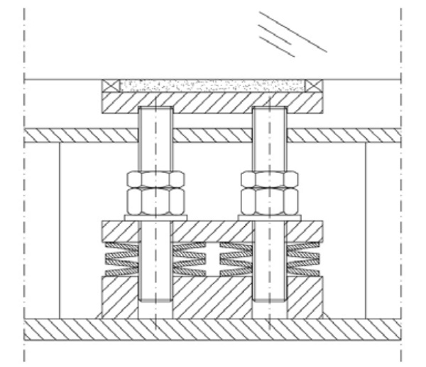
In this case, the use of elastic supports along the bottom edge of the panels (fig.4) permitted to accomodate the slab deflections making them compatible with the structural silicone bonds and avoiding detachment of glass from its support pads for all considered load combinations.
Most often, Belleville springs are adequate for the construction of such elastic supports in which relatively high forces and small displacements need to be accomodated. They provide a relatively linear response along their full working length.
A different approach was used in a retail shop in the Middle East in which a 12m tall façade on a concrete slab was made relatively insensitive to the slab displacements by supporting the weight of the cladding panels with a single resin pad located at the centre of their bottom edge. The in-plane rotation of the panel was impeded only by the structural silicone joints along the vertical edges of the panel whereas out-of-plane displacements were blocked mechanically. The differential vertical displacement between adjacent panels produced a shear displacement at vertical joints that had to be accomodated by the structural silicone.
Embedded metal inserts
Another common characteristic of the projects discussed in this paper is the use of adhesive connections in which a metal part is embedded in a glass laminate. In this case, a laminate with a minimum of three glass plies is necessary, with the central ply having a notch that accomodates the metal insert. The bond is provided by the interlayer adhering to both glass and metal during the lamination process. Therefore, the interlayer must have sufficient strength and good affinity with metals, which makes it a perfect application for a ionomer interlayer like SentryGlas.
Besides the obvious visual advantages of these connections, arising from the transparency of the adhesive and unobtrusiveness of the metal parts, their mechanical behaviour is quite complex even under the simplest loading conditions such as a pull-out force.
As discussed in [4], a pull-out force on the metal insert is transferred to glass by shear on the lateral surfaces, shear on the top and bottom surfaces and tension on the frontal surface (fig.5). The distribution of the force between these mechanisms depends on their relative stiffnesses.
At room temperature and under short term loads, the displacement of the interlayer on the front surface in a direction perpendicular to the force is significantly restrained by the adjacent interlayers and glass panels. This fact, combined with a relatively high Poisson ratio, leads to the force being mainly transmitted by the front surface to the inner glass ply. This mechanism also exists at higher temperatures and for longer load durations, but it is less significant due to the lower lateral constraint provided by a softer interlayer.

In addition to the stresses produced by the applied forces, there may be some residual stresses as a result of the lamination process. The difference in the thermal expansion coefficient and the specific heat between glass and metal produces some differential displacements during the cooling phase of the autoclave cycle. To the authors’ knowledge, a quantification of this effect is not yet available in the literature. However, it is well known that metals with physical properties quite similar to glass (titanium alloys) are easier to laminate than, for instance, typical stainless steel grades.
The combination of relatively high stresses in the frontal bond resulting from external forces and some unknown residual stresses may produce delamination in this area. In fact, the region more prone to delaminate is the curved transition between the frontal and the top/bottom surfaces, which is subject to a combination of tensile and shear forces. Delaminations in these areas appearing spontaneously during the first week after lamination have been observed occasionally
The numerical prediction of the strength of embedded laminated connections is an active field of research. The recent publication of the excellent PhD thesis of M. Santarsiero [6] and some related scientific publications [4-9] has shed some light on this issue. However, the results shown in these publications cannot be directly used for design for the following reasons:
a) All results are based on average values obtained from testing. Average strengths are totally correct in a scientific work but cannot be used for design.
b) All tests are performed on glass-tostainless steel connections. Thus, lab test results in these publications need to be cross checked if other metals (e.g. titanium alloys) are used, although important differences in bond strength are not expected.
c) A method to account for the simultaneous application of tensile and shear stresses, together with the existance of both deviatoric and volumetric stresses is proposed in the thesis. This method needs to be further verified with physical tests before being applied for design.
d) A quantification of the residual stresses resulting from the lamination process and their relaxation with time and temperature is still an open field for research.
Until further information on this subject is available, the following design approach for the adhesive bond is suggested:
a) Use the embedded adhesive connections to transfer short term loads exclusively.
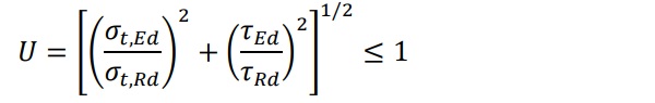
b) Determine the design strength of the bond in pure tension and pure shear by testing, for the intended temperatures and load durations. The design strength is the characteristic strength as per Eurocode 0 (5%-percentile of the distribution of strengths with 75% confidence) divided by a material factor obtained from [10].The following interaction expression was obtained from Peters [11] and adapted to this application. Note that it ignores the existance of hydrostatic stresses.
The Generalized Triaxial Model (GTM) proposed by Santarsiero and Louter [6, 7] may be a more adequate approach.
c) Analyse the embedded connection in Ultimate Limit State (ULS) with sufficiently accurate finite element models considering the frontal, top and bottom surfaces, together with a 10mm strip on the lateral surfaces, to be completely delaminated (fig 5). In addition, a 5mm strip on the lateral surface adjacent to the outer edge is not considered to participate in the force transfer as adhesion may be affected by environmental influences, as shown in [12]
Therefore, only the central part of the lateral surfaces participate in the force transfer in ULS. This area is mainly subject to shear stresses, although some tensile stresses may also be present due to the deformation of the outer glass plies.
d) Cross check numerical results with some physical tests of the final connections. With regard to the design of glass, the scenario in which no delaminations exist in ULS should be considered for the determination of the maximum stresses in the central glass ply. At the same time, the scenario of maximum delamination as noted above is to be considered for the design of the outer glass plies.
Obviously, stresses on glass arising from bending of the panel (in addition to pull out forces) should also be taken into account. These may be quite relevant in long glass fins or beams with metal inserts on their tensile fibre, where the notches created to accomodate the insert produce significant stress concentrations.
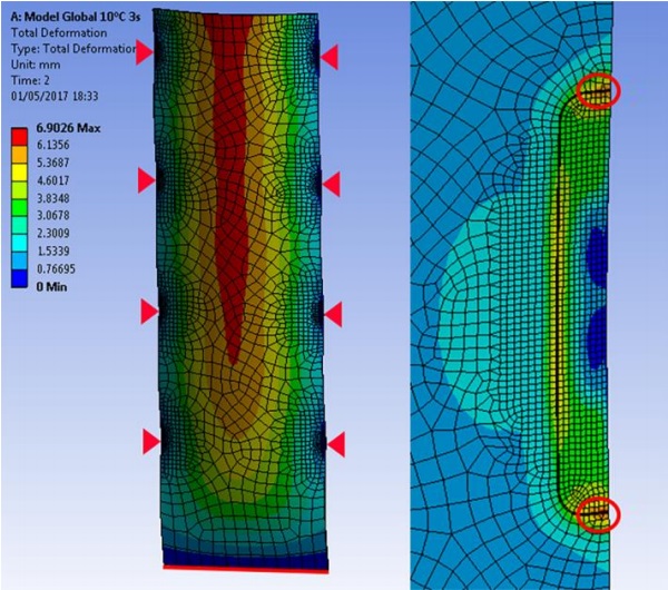
In some circumstances, it is possible to take advantage of the metal inserts to help alleviating stress concentrations due to bending of the glass panels. For instance, in the entrance hall of an office building in Madrid (currently in construction) significant stress concentrations occured around inserts of the cladding panels. These are 10+15+10mm laminates with a 1.52mm SentryGlas interlayer and a typical size of 3x10 m (b x h) fixed continuously along their bottom edge and at four points along their vertical edges by means of titanium inserts connected to internal glass fins. Only out-of-plane wind loads are transferred through the inserts by means of a clamping system.
Significant stress concentrations were found on glass and on the interlayer due to the high curvature of the panel around point fixings combined with the sudden stiffness change at the top and bottom edges of the insert. Stresses could be significantly alleviated by extending the height of the inserts from the initial 240mm up to 400mm in order to locate the transition from metal to glass in an area of small curvature, as shown in fig.6.
Conclusions
This paper has described some connection designs used in a number of recent structural glass projects, together with the techniques used for their structural analysis and design. A number of topics which require further research have also been identified, specially in the field of embedded laminated connections. Research organisations are encouraged to progress on these topics which have a clear industrial interest.
References
[1] ETAG 002 “Guideline for European Technical Approval for Structural Sealant Glazing Kits (SSGK). EOTA, 2012
[2] Design stress for DC structural silicones, Dow Corning GmbH, 2015
[3] Sandberg L.B., Ahlborn T.M. “Combined stress behaviour of structural glazing joints”. J.Struct.Eng. 115 (1989) p.1212-1224
[4] Santarsiero M., Louter C. “Embedded and point laminated adhesive connections for glass structures: parametric non-linear numerical investigations”. Proceedings of Glass Performance Days 2013
[5] Santarsiero M., Louter C. “Preliminary studies on the mechanical behaviour of thick embedded laminated connections. Proceedings of Glass Performance Days 2015
[6] Santarsiero M. “Laminated connections for structural glass applications” PhD thesis nº 6828. École Polytechnique Fédérale de Lausanne. December 2015
[7] Santarsiero M., Louter C. “Failure criteria for SentryGlas ionomer and TSSA silicon: a theoretical introduction to a novel Generalized Triaxial Model (GTM)” Proceedings of Challenging Glass 5. Ghent, 2016
[8] Santarsiero M., Louter C., Nussbaumer A. “Laminated connections for structural glass applications under shear loading at different temperatures and strain rates” Construction and Building Materials 128 (2016) p.214-237
[9] Santarsiero M., Louter C., Nussbaumer A. “Laminated connections for structural glass components: a full scale experimental study”. Glass Struct. Eng. 2017
[10] “Guide to the structural use of adhesives” The Institution of Structural Engineers. London, 1999
[11] Peters S. et al. “Ganzglastreppe mit transparenten SGP-Klebeverbindungen – Konstruktion und statische Berechnung” Stahlbau 76 (2007), Heft 3
[12] Gallizia M., Scheers J., Arbos F., Teixidor C. “Point fixed SentryGlas overhead glazing: 11 years ageing performance” Proceedings of Challenging Glass 4. Lausanne, 2014