Source:
Challenging Glass 7
Conference on Architectural and Structural Applications of Glass
Belis, Bos & Louter (Eds.), Ghent University, September 2020.
Copyright © with the authors. All rights reserved.
ISBN 978-94-6366-296-3, https://doi.org/10.7480/cgc.7.4503
Authors:
Maximilian Laurs
Benjamin Schaaf
Pietro Di Biase
Markus Feldmann
Institute of Steel Structures, RWTH Aachen University

In today’s architecture the bending of glass plays an important role in achieving free forms in modern façades. In addition to the usual procedure of hot bending glass sheets into the desired shape, the option of cold bending is being used more and more frequently. In this process a glass pane is bent into the desired shape and fastened to a substructure without prior heating and at low cost.
This inherent bending state comes along with different beneficial but also with some unfavourable perks that have to be considered in the engineering process. The resulting influences on the strength of the glass and stiffness of the overall system are investigated in a German research project. In large-scale tests, special attention is paid to the established shape of the pane during the bending process and the resulting load on the steel substructure.
1.Introduction
Glass is recently becoming a more and more frequently used material in modern architecture. Architects striving for evermore filigreed supporting structures and transparent building envelopes depend on advanced research and development in terms of material and geometrical behaviour as well as an introduction of normative regulations regarding conventional applications and cold bending procedures. In order to achieve smooth envelopes, engineers, up until now, where forced to tessellate the desired shape into many small subareas consisting of plane surfaces.
With decreasing size of the subareas, the desired shape could be approximated more precisely. However, this fractionation always involves a growing portion of opaque substructures supporting the small panels, which can only be engineered finitely small, confined by its required loading capacity.In order to combine the aspirations of utmost transparency and the most precise and possible approximation of the desired shape, methods were developed, allowing the bending of larger glass panes into the intended form.
On one hand the method of hot bending is used. In this process the glass is heated up to its glass transition temperature and, while still in its viscous state, bent over a prefabricated negative form by its self-weight. After annealing, the pane stays in the exact form of the mould and yields no inherent stress distribution. This bending method is quite material-and energy-intensive, for the panes have to be heated up to a temperature above their transition point and additionally for every subpart of the desired shape a new individual mould has to be produced.
Using this method small radii of curvature on single-and double curved surfaces can be achieved. On the other hand, cold bending provides the engineer with two different approaches. Namely the cold-lamination and the elastic cold-bending technique. Both are cost efficient and without the need of a fire resistant negative form. Another commonality is the use of external forces to bring the panes into the desired shape. Whilst the first holds the reaction forces through a lamination process, the second is obliged to a supporting structure using clamps or strips holding the edges or corners in place.
As the name suggests the former technique is only applicable on laminated glass, but the second procedure can be used on insulating glass units, laminated glass and single glass panes. In general, both methods use thermally toughened and heat strengthened glasses. During the cold-lamination-bending the panes, separated by sheets of polymer, are deformed into the desired shape, using a bending device or negative form.
This elastic bending state is maintained during the successive autoclave lamination of the package under high pressure and temperature. The established shear bond between the layers then conserves the elastic bending and constitutes, apart from a small spring back and relaxation phenomena due to the viscoelastic properties of the foil over time, a curved geometry.
However, the calculation of the behaviour after the release of the substructure and the time-dependence is costly and difficult to predict. Similar to the hot bending technique the cold-bent pane also has to be transported from the manufacturer to the building site in its bent state, which confronts the user with higher transportation costs, compared to the transportation of plane glass sheets.
Therefore the usage of elastic cold-bending seems to be a promising method, omitting factory-set productions and high computational efforts. But despite all its benefits, the elastic cold-bending of glass is still subject to some phenomena the executing engineer needs to bear in mind (Feldmann 2012). Namely the aspects of strength, stability and form finding.
2. Background
The production of multi-axially bent glazing can, within certain limits, be achieved by cold bending, without being susceptible to the problems of the other methods mentioned above. In recent years there has been increased research on cold-bent glass, which has revealed first limits of its application in terms of form finding. The establishment of these forms and its conditions must be understood in detail. An overview of possible geometries is given by Beer (2017).
If glass panes are cold-bent, different bending shapes are automatically realized. These depend on the supporting conditions of the pane. If the pane is held only at its corners, the edges can deform freely. As a result of the same displacement of two adjacent corners out of the plane, a surface with a simple curvature is obtained. If a single corner is moved perpendicular to the plane, it results in a doubly curved geometry. Similar forms are created when the panes are line-supported.
If two opposite edges are fixed, uniaxially curved surfaces can be created. When two adjacent edges, or more, are supported and the opposite corner is shifted out of the plane, a biaxially curved surface is created again. For biaxially curved surfaces, the signs of the individual principal radii of curvature are relevant. With the same sign the pane constitutes a synclastically curved surface (dome), with different signs an anticlastic surface (hyperbolic paraboloid).
In both cases, plates are transferred from two-dimensional to three-dimensional structures (shells). In the case of the hyperbolic paraboloid, it should be noted in particular that it is not a developable surface. This means that the flat pane can only be transformed into this shape by distorting its surface. The resulting stresses of the cold-bending limit the choice of glass type to tempered glass types. Since the outer fiber of the shell is under constant tensile stress, only the compressive stresses introduced by prestressing can suppress crack growth. During elastic cold-bending, two geometric states have to be distinguished.
The geometric linear deformation of plates was already extensively investigated by mechanical engineers like Timoshenko and Kirchhoff, who build the foundation of the calculation of loaded plates. Both limited their work to small deflections of plates, reaching by rule of thumb up to magnitudes of the thicknesses of the plates, where effects of geometric nonlinearity do not influence the loadbearing behaviour of plates decisively.
If the deformation rises further, membrane effects, depending on the current deformation of the plate, can influence the load bearing behaviour significantly. These nonlinear effects can today be accounted for by using FE analysis and play an important role in the field of cold-bending, for higher deflections of the plane pane are generally desired.
The elastic cold-bending of glass panes has been bothering researchers for years. A great deal of most diverse research has been conducted including different loading and supporting conditions, varying sheet dimensions, glass thicknesses and all available sorts of prestressed glasses, reaching from thermally prestressed to chemically toughened glasses.
Results to be mentioned, focusing on point-supported setups, are the scientific works of Herwijnen (2004), Gallupi (2014a) and Datsiou (2016), while perimeter line-supported panes were investigated in Beer (2013), Bensend (2016 and 2018), Hoffmeister (2016), Galuppi (2018) and Nehring (2019), where as the latter focuses on thin glasses with thicknesses smaller than 4 mm. In the first-mentioned research just one clamp on a corner was moved outside of the panes initial plane, while the edges remained free.
The latter also moves one corner outside of the initial plane, but at the same time restrains the deformation of the edges. A vast multitude of different buckling limits and analytical approaches has therefore been accumulated and many FEAs have been conducted. To understand the crucial differences between the prior mentioned aspects and parameters, those are outlined in the following paragraphs.
2.1. Support Conditions and Reaction Forces
The glass industry provides architects and engineers with a wide variety of supports to install cold-bent glass elements in façade structures. Ranging from the group of point supports, like clamps or glass fittings, to line supports like silicone glazings on frames and glass profiles. The decisive difference in those support conditions regarding cold bending is the deformability of the panes edges.
While indifferent in the vicinity of small deflections, the edges of point-supported panes start to lose their straightness due to larger deflections. This arises from higher order geometric nonlinear influences, where membrane stresses in the mid-plane of the pane influence the overall load bearing behaviour and ultimately the pane starts to buckle (Datsiou 2016).
The edges are stiffened by the supports and therefore change the behaviour of the plate during the deformation of a corner. The resulting support conditions, restraining only deformations and not rotations perpendicular to the edge, resembleedge-hinges. Although the broadness of the supporting strip can contribute to a rotational stiffness. The mentioned deformation change of the edges ultimately leads to a change of the resulting reaction forces along the edges. While all reaction forces are concentrated in the corners for linear theory, they get distributed in a wavelike fashion along the edge for higher deformations of one corner (Galuppi 2014). The exact distribution depends on the degree of cold-bending. While symmetrical at first, the force distribution gets asymmetrical with rising deformation.
The dimensions of the plane vary strongly through the above mentioned papers. Whereas Beer (2019) and Bensend (2018) focused on dimensions used in actual buildings, this paper concentrates on quadratic glass panes. This geometry is of special interest regarding geometric nonlinearities, for the membrane effects form most strongly under these circumstances. The smallest used thickness is 4 mm, for it is assumed, that using smaller thicknesses, like in Nehring (2019), membrane effects govern the load-bearing behaviour. Thicker glasses promise a combination of bending and membrane action and therefore tend to be of higher interest for the general use.
The works of Galuppi (2014a) and Datsiou (2017), while studying the behaviour of doubly-curved glass lites, observed a deformation dependent buckling phenomenon. This occurred during rising corner deflections of point-supported specimens. At a critical deflection δ the behaviour of the plate changes. While at first the deflection of both diagonals increases alike, one diagonal flattens out again from this point and the initially straight edges begin to deform.
However, this phenomenon occurred earlier with point-supported panels, where as perimeter-supported panels have a higher resistance to buckling. This is due to the fact that the change of shape of the edges is prevented by stiffening effect of the frame construction or the line supports. An analytical approach predicting the load deflection behaviour is presented by Galuppi (2014a), but limited to point supported plates.
2.2. Buckling Phenomenon
Following the approach of above mentioned authors, the deflections of the diagonals are used to detect the moment of buckling. Later on the load diagonal is the distance between the corner with the maximum deformation and the opposite corner. The transverse diagonal is the distance between the two remaining corners. All deformations are normalized to the center of the pane. Therefore δ is the sum of the deformations of two adjacent corners relative to the deformed midpoint. More precisely δ1refers to the deformation of one corner of the load diagonal and δ2 to one corner of the transverse diagonal, see Figure 1. The applied deformation dZ is also denoted.
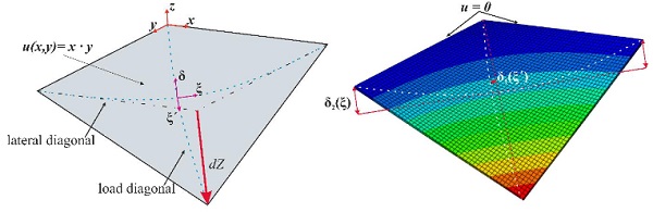
Both are related to the length of the diagonals normalized to 1 (ξresp. ξ ́). In the case of small deformations, more specifically deformations dZ smaller than the plate’s thickness t, when Kirchhoff's plate theory is valid, the deflections of both diagonals δi are equal. As soon as the edges of point supported panes would start to deform, but are held back by the clamping bars, an asymmetry is formed. In relation to the center of the specimen, the diagonals deform to varying degrees (δ1>δ2).
In van Herwijnen (2004), a linear relationship was described between the critical deflection dZbuckl and the thickness d of the glass for point-supported glasses. At the same time, this branching point dZbuckl marks the beginning of the buckling of the edges or, in the case of line-supported panes, the redistribution of the supporting forces from the corners to the entire edge.
A perimeter supported glass pane submitted to cold-bending, therefore, seems to feature promising characteristics. For this reason a German research project was started to equip engineers with design rules regarding the elastic cold-bending of glass panes. Using a wide range of test series the behaviour of bend plates during the bending process and limits of application should be revealed. These next chapters cover findings regarding quadrilateral panes and the development of their form during bending and the corresponding stress distribution.
3. Experimental Investigations
The scope of the testing included 24 tests in total. Considering glass thicknesses of 4, 6 and 8 mm (4 specimens each) and both toughened and heat strengthened glasses. Parallel numerical investigations have been conducted. The test setup and the numerical modelling are described in the following paragraphs.
3.1. Experimental Test Setup
The following described test setup was designed to force the glass pane into a hyperbolical paraboloid form while holding the edges in their initial straight form. Therefore all edges were placed on semicircular steel bars, which were plastered with EPDM rubber. This way a rotational free support was realized and the glass was protected from harm, resulting from the hard contact with the steel support. One corner was connected to the hydraulic cylinder, which was used to induce the force. It was connected by a calotte bearing, to eliminate potential constraining forces. The degrees of freedom can be seen in Figure 2.
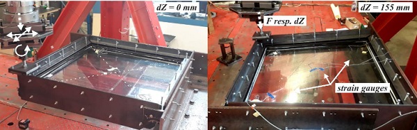
The force moves two neighboring perpendicular edges out of the plane, so that the displacement along the edge rises linearly. The pane is therefore bend along one of its diagonals. The investigated edge lengths were 1000x1000mm and, therefore, had an aspect ratio of unity. While the applied force and corner displacement was measured by a potentiometer and an applied force sensor, strains were recorded on relevant discrete points using strain gauges.
Those were applied along the diagonals following each’s direction. Two were placed in the middle, perpendicular to each other, while two others were placed on the diagonal with a distance of 200mm to each edge. The directions of the strain gauges align with the directions of the principal stresses calculated in a foregoing prognostic FEA. All strain gauges were placed on the top side of the plate. The deflection of the plate’s center was measured using a linear potentiometer.
This is used to detect the previously explained buckling behaviour. All tests were conducted with a rather slow loading speed of 0.5mm/sto eliminate dynamic effects. The specimens were loaded until failure occurred. Before the tests were conducted the residual stresses of all panes were measured on five points on the topside using a scattered light polariscope.
3.2. Load-deflection Behaviour
The applied load was measured during the whole bending process, its correlation to the corner displacement is shown representatively for a 4, 6 and 8 mm pane in Figure 3 on the left side. The influence of the thickness on the loadbearing behaviour is obvious, although not linear. Higher thicknesses require a higher load to achieve the same deflection. The non-linear behaviour corresponding to a stiffening of the structure is obvious.
The use of toughened glass enables higher possible deformations, due to higher compressive residual stresses compensating load-induced tensile stresses. The curves were smoothened using a lowpass filter in aid of comprehensibility, since the constant self-adjustment of the calotte bearing led to a negligible scatter in the force signal.
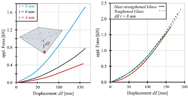
The maximal deflection therefore depends on the thickness and the residual stress state of the investigated pane.
3.3. Characterisation of Established Shape
During the whole testing procedure, two different established shapes were observed. The mentionable differences are explained in this chapter. The first shape is characterized by a flattening of the diagonal reaching from the load introduction to the opposite corner (load diagonal), the second showed this shape shift on the other diagonal, connecting the remaining corners (transversal diagonal), see Figure 1.
Those two states lead to different stress states monitored by the strain gauges and will be called deformation mode 1 (load diagonal flattens) and 2 (transverse diagonal flattens) later on. The different shapes cannot be distinguished in the load deflection curves, but the midpoint reflection umid relative to the total corner displacement dZ changes significantly, see Figure 4 (left).
Those two states where identified as the two possible buckling states of a line-supported quadratic plate.They could be associated to the different tests by a comparison of the deflection of the midpoint, relative to the applied corner displacement, see Figure 4 (left). The linear behaviour of this graph branches into two separate graphs, once a critical displacement is reached. The upper branch corresponds to an initial displacement of the panes center antagonized to the corner’s deflection direction. This leads to the shape of mode 1. The second results from a prior deflection in the direction of the corner displacement dZ, with deformations representing mode 2. Each graph results from a different specimen.
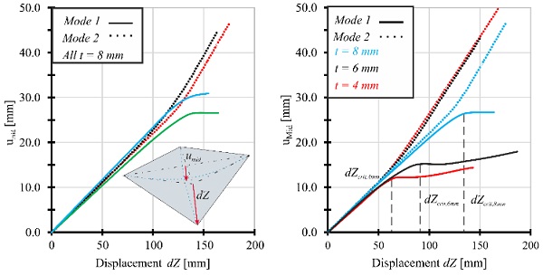
The point of branching is postponed for thicker plates. A linear relation between thickness and branching cannot be attested as seen on the right side of Figure 4. It is interesting, that the mode 1 deformations of 4 mm and 6 mm are similar in their course. This might mean, that the influence of the bending effect in the 6 mm pane is still small and its behaviour is mainly governed by membrane actions. It is also obvious, that the midpoint deflection never gets negative. This would represent the “Warp Mode 3” of Beer (2013). Both modes achieved in this paper can be assigned to Beer’s “Warp Mode 1”.
4. Numerical Investigations
Following this earlier explained differentiation of the two modes, numerical investigations were conducted. Those are outlined in this chapter. They were compared to measured strains and used to estimate the stress distribution over the whole plate.
FE simulations were carried out at the Institute of Steel Construction at RWTH Aachen University to estimate the expected forces in the tests and to then compare them with the results of Galuppi (2014a) and Datsiou (2017). The implemented deformation figures should correspond to those of the designed test stand. All calculations are performed with the program ABAQUS 2018. The glass pane is held hinged at all edges.
Two of these edges are shifted out ofplane in a linearly increasing manner over their length. This displacement is applied via boundary conditions. As in Galuppi (2014a) and Datsiou (2017), the displacements of the diagonals and the maximum occurring stresses are evaluated. Additionally, force-deformation diagrams are generated. The calculation is exclusively geometrically non-linear, since large deformations are to be applied. The material behaviour is linear-elastic with a modulus of elasticity of E=70000MPa.
The plate thicknesses are constant over the whole plane, but vary according to the planned tests. The elements are C3D20R cube elements, i.e. square volume elements with reduced integration points. To provoke buckling, a uniformly distributed surface load of p = 0.0001Nmm-2 is applied. Otherwise the diagonals would not bulge, corresponding to a very unstable constellation from a global perspective. Before the corner deflection was applied, the surface load was removed. Thus the calculation starts with a slightly bent pane, which is equivalent to an imperfection. During bending a surface load simulated the dead weight of the plate.
4.1. Buckling Phenomenon
Figure 5 (right) shows how the parabola of the transverse diagonal flattens with increasing bending and its share the δ2 of the total deformation δ decreases (δ2< δ1). Because of symmetry reasons the graphs are only shown over half a length of a diagonal. The flattening diagonal will be called transversal diagonal later on. Figure 5 (left) shows the influence of different thicknesses. A correlation between the thickness tand the critical deformation δcrit can be attested for line-supported panes. The thicker the glass, the later buckling occurs. Therefore the asymmetrical rearrangement of the diagonal’s deflection sets in later for thicker lites.
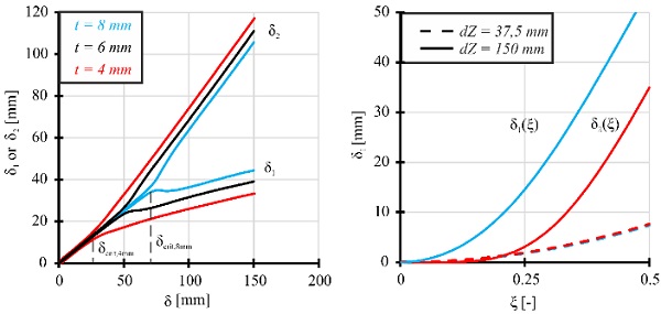
Which one of the two parabolas flattens depends on the direction of the pre-imperfection relative to the deformation dZ. In both cases in the beginning the figure resembles a hyperbolic paraboloid shape and therefore an anticlastical surface. Without the imperfection the linear behaviour of the beginning of the graph would carry on. In the tests this initial deformation might be induced through clamp forces resulting from the supports, pressing the pane up-or downwards.
Noteworthy is the fact that this occurs later than predicted from van Herwijnen (2004) for point-supported glass, underlining the beneficial higher buckling resistance of line-supported lites. Galluppi (2014a) supposed a buckling limit of dZ/t=18 for line supported panes, which seems quite high for the assessed tests.
4.2. Stress Distribution
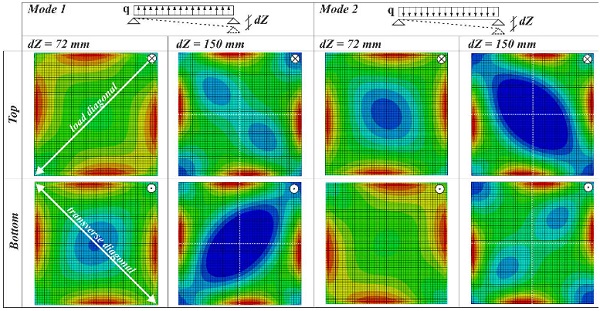
Most glasses are dimensioned via their maximal principal stresses occurring during their service life. In the case of cold-bent glass, a thorough understanding of the constant stress state imprinted by the cold-bending is therefore vital. This stress state of cold bent glasses is a rather complex one and changes during the bending due to the activation of membrane stresses. Figure 6 shows the qualitative maximal principal stress distribution of the panes top and bottomside due to different cold-bending states.
The position and direction of dZ is denoted in the upper right corner of every pane. The direction of the imperfection is denoted next to the respective buckling mode. On the left sidein the first state, the glass is still in its unbuckled state, represented by a stress state, where the stress along both diagonals is the same. The highest stresses are located at the middle of each edges lightly shifted towards the edges of the transverse diagonal.
In the second state, one can see how the distribution changed. Therein, the transverse diagonal shows two spots with significantly lower stresses. This represents the flatten ingor buckling of just this diagonal. This is the reaction to aninitial imperfection that was opposed tothe direction of the corner displacement. Therefore, the plate buckles into the earlier described mode 1. This buckling is accompanied by a concentration of stresses in the corner of the buckled diagonal.
Contrary to this, the right part of the Figure shows the buckling of the loading diagonal, representing Mode 2. The centers of the edges are denoted for better comprehensiveness. It is evident, that the modes are basically equivalent. The distribution is rotated by 90 degrees around the z-axis and the pane’s bottom becomes its top. Yet, the displacement figure should be of interest for the stresses induced by wind or other variable loads need to be superposed with the resulting inherent stress state on the investigated side.
The numerical stresses were compared to the respective measured stresses to validate the model. Although the maximum occurring stresses could not be measured directly, they can be derived from a fitting stress state from an FEA, calibrated to the experimental results.
4.3. Support Reactions
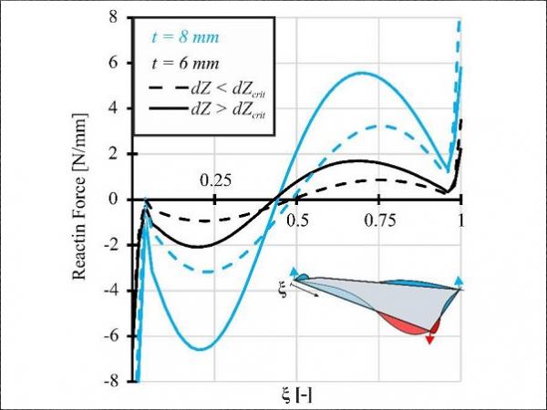
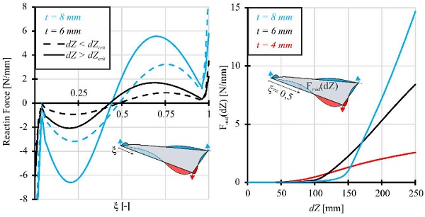
Figure 7 shows the reaction forces calculated through the FEAalong the edge’s length normalized to 1. The linear plate theory according to Kirchhoff calculates support reaction forcesonly, even forperimeter supported plates, in the corners of the plate. The FE model can predict those correctly for small deformations. If the deflections rise further, those support reactions get distributed along the edges. The plates behaviour is geometric nonlinear. This is depicted by the dashed line on the left side of Figure 7.
The reactions forces of the thicker plate are naturally higher. The above mentioned critical deformation state, where buckling occurs, also states the change of the reaction forces, when they get distributed asymmetrically over the length of the edges.The null moves towards the corner reaction force of the unbuckled diagonal. The continuous line depicts just this case, but refers to different corner displacements dZ for different thicknesses. On the right side of the figure the influence of the thickness on the change of reaction force distribution is shown. The plate buckles, when the reaction force Fmid in the middle of the pane becomes non-zero.
5. Results
The numerical and experimental results were juxtaposed and the quality of the FEA was valuated. Influences of thickness and the deformation mode on stresses and the buckling behaviour have been assessed.
5.1. Stress states
During the testing the different deformation modes could be identified using the applied strain gauges. Those were also used to validate the presented numerical model. Figure 8 shows the comparison of numerical and experimental values of a 4 mm thick pane with the dimensions of 1000x1000mm. The two possible deformation states result in different measured stresses.
While the left side depicts Mode 1, the right side shows the stresses measured on panes in Mode 2. In case of the first mode strain gauge 1, 2 and 3 (SG 1-3) are positioned on the transverse diagonal, the one buckling in this case. In Mode 2 the buckled diagonal is only observed through SG 4. The numerical results show a good agreement especially in the unbuckled state. The moment of buckling is denoted by a sharp bend of all measured strains.
The calculated corresponding dZ value fits very well with the experimental observed one. In the post-buckling regime, the calculated values deviate from the experimental ones, especially in the case of SG 1. The qualitative characteristics of the process is nonetheless depicted quite accurate. The deviation might result from the continuous elastic support, due to the EPDM layers, which is simulated perfectly rigid in the FEA.
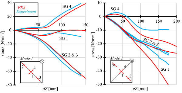
The different stress values imply, that the assessed buckling mode could be used in favour of the load bearing capacity. If a pane deforms to Mode 2, variable loads causing tension on the top side of the plate could be resisted far better than in Mode 1. Although, if the direction would change, like it is the case with wind loads, this positive effect would be canceled out, because of the tension stresses on the bottom side. Generally the buckled shape should be avoided, because it can lead to optical derogations, as described in Beer (2013).
The effect of different thicknesses on the measured stresses can be seen in the following graphs. The depiction is limited to panes in Mode 2, which occurred more often. This is most likely the case because of the influence of the dead weight, which has the same direction as the deformation in the test setup and therefore leads to Mode 2. Mode 1 is only realized by horizontal glazings, when they are bulged upwards by imperfections, or through clamping effects.
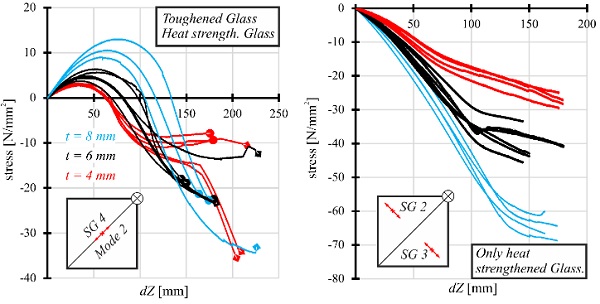
Figure 9 shows the measured stresses for different thicknesses in relation to the cold-bending state of the pane. Naturally the same deflections result in higher stresses in thicker panes. Therefore the highest stresses were measured in the 8 mm panes. All graphs show the same qualitative progression. With higher thicknesses the graphs tend to deviate more, but in a reasonable range of small stresses.
The critical dZ values can also be derived from these figures. They are either denoted by a sign change of the stresses on the buckling diagonal, or by an up-bend of the course of the stresses of the transverse diagonal. One bend is especially strong, indicating, that the pane was influenced very little by a pre-imperfection and changed into the buckled mode very suddenly. Given the complex and in homogeneous stress distribution over the plate, the limited accuracy in strain gauge application and the small stress values, the results seem quite satisfying. Noteworthy is the course of the two 4 mm toughened glasses indicating a second change of deformation that was only observed once.
5.2. Prediction of Maximum Principal Stresses
Because of the good agreement with the experimental results, it can be assumed, that the FEA is capable of an accurate prediction of maximal stresses in the pre-buckling range of dZ. This will be a useful tool in the effective design of cold-bent perimeter supported glazings. Figure 10 shows the dependence of the maximal occurring principal stress and the applied corner displacement dZ for the investigated thicknesses. The point of deformation change is denoted. It is to be kept in mind, that the depicted stresses only describe the inherent stress state. Stresses induced through wind loads or other actions need to be assessed additionally.
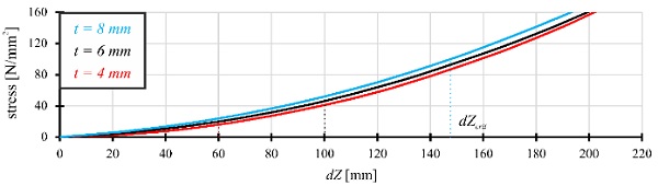
In the end it is to be assessed up to which extend the glass is to be bent in order to fulfill serviceability standards and an effective utilization of the used glass thickness.
5.3. Fracture patterns
The post-fracture behaviour is also of high importance in the case of bent glass. Although it is commonly not used as accessible glazing, it has to withstand a certain time period before its total collapse, if it is used for example as roof glazing. The maximal possible time the glass is able to remain in place is strongly dependent on the fracture pattern of the glass.
Due to a thin foil plastered on the upper side of the test specimens, it was possible to detect the fracture origin and to evaluate the fracture pattern and crumb characteristics although no layered glass was used. From these findings first assumptions on the post-fracture behaviour of laminated glasses can be derived. Figure 11 shows the characteristic occurring fracture patterns using toughened or heat strengthened glasses.
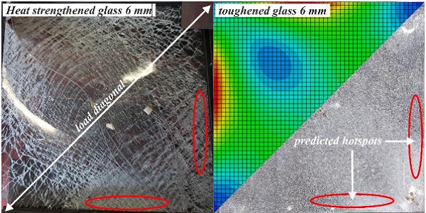
During the whole testing series two possible fracture patterns were observed. Those could be assigned to the formerly described deformation modes 1 and 2. The influence of the imprinted stresses on the fracture patterns was obvious. The maximum principal stress concentration in the pane, resulting in a higher strain energy density level. This lead to a generally finer fracture pattern, featuring smaller crumbs than unbend strengthened glass, as stated in Pourmoghaddam (2018).
While the finest fracture pattern was observed in the predicted regions of highest principal stresses. This proved to be true for both tested glass types. Figure 11 denotes the regions of the finest crumbs, where also the highest principal stresses where predicted. Therefore, the finest crumbs were found in the edges of the buckled diagonal. From this fact it can derived, that both shown panes buckled into Mode 1.
Regarding the post breakage behaviour it can be predicted, that cold-bent glass, on the one hand will feature an impaired post breakage stiffness compared to unbend glass due to the smaller fracture pieces. On the other hand the shards tend to interlock more, conditioned by the curvature of the pane, resulting in a higher stiffness. The overall influence needs to be assessed during the examination of laminated glass unitsin following investigations.
6. Summary and outlook
In this paper the preliminary results of the German research project processed at the Institute of Steel Construction at RWTH Aachen were presented. Tests on 1000x1000mm glass panes with three different thicknesses were run, including both, toughened and heat strengthened glasses. Those panes were deformed by a corner displacement, while all edges were linearly supported.
Strain gauges and distance measurement allowed a comprehensive observation of the mechanical reactions of the plate. The buckling behaviour described by former researchers could be observed and two possible deformation states were identified and characterized. To enable further insight on the behaviour of the plate an FEA was conducted. This FEA computed fitting stress behaviour for the pane especially considering the unbuckled states. The fracture pattern of the broken panes implied that the change of the stress distribution resulting from higher corner displacements would fit well,too. Therefore maximal occurring stresses, ultimately leading to failure, could be predicted in correlation to the bending state.
In further investigations, the resulting stiffness of cold-bend and ultimately buckled panes needs to be assessed to predict the behaviour of loaded cold-bent glazings. Of special interest might be the manipulation of the buckling behaviour via an intentional imperfection, leading to the mentioned different, maybe beneficial, deformation states.
This could especially prove convenient in the case of isolating glazing units, which are exposed to a constant pressure load. Further the influence of the cold-bending on laminated glasses is to be investigated. The constant shear forces evoked through the cold-bending, will most likely lead to non-negligible creep effects and, therefore, influence the overall loadbearing capacity and behaviour. These studies will all include the influence of different aspect ratios of panes edges. In the end the here introduced FE model will prove valuable in those upcoming investigations.
7. Acknowledgements
The presented results were developed within the framework of the research project “Kaltgebogenes Glas”, IGF-No. 20191N. The project was funded by the Arbeitsgemeinschaft industrieller Forschungsvereinigungen "Otto von Guericke" e.V. (AiF) from funds of the Federal Ministry of Economic Affairs and Energy (BMWi) on the basis of a decision of the German Bundestag. The project is conducted by the Institute of Steel Structures of the RWTH Aachen University.
8. References
Beer, B.: Complex Geometry Facades –Introducing a New Design Concept for Cold-Bent Glass. Glass Performance DaysProceedings (2013)
Beer, B.: Free-Form Shape Cold-Bent Structural Silicone Glazed Facades –Design Concept and Challenges. Glass Performance DaysProceedings (2017)
Beer, B.: Options for Complex Geometry Facades –Single Corner vs. Free Form Cold-Bending. Glass Performance DaysProceedings (2019)
Bensend, A.: Maximizing the Twist of Cold Formed Glazing. Challenging Glass Conference 5 Proceedings (2016). doi: https://doi.org/10.7480/cgc.5
Bensend, A.: The Effects of Cold Warping on Glass Stiffness. Challenging Glass Conference 6 Proceedings (2018). doi: https://doi.org/10.7480/cgc.6
Datsiou, K., Overend, M.: The mechanical response of cold bent monolithic glass plates during the bending process. Eng. Struct. (2016). doi: https://doi.org/10.1016/j.engstruct.2016.03.019
Datsiou, K.: Design and Performance of Cold Bent Glass. Doctoral Thesis, University of Cambridge (2017). doi: https://doi.org/10.17863/CAM.15628
Feldmann, M. Kasper, R., Langosch, K.:Glas für tragende Bauteile. Werner Verlag, Köln (2012)
Galuppi, L., Massimiani, S., Royer-Carfagni, G.: Buckling phenomena in double curved cold-bent glass. Int. J. Nonlin. Mech. (2014a) doi: https://doi.org/10.1016/j.ijnonlinmec.2014.03.015
Galuppi, L., Royer-Carfagni, G.: Rheology of cold-lamination-bending for curved glazing. Eng. Struct. (2014b) doi: https://doi.org/10.1016/j.engstruct.2014.01.003
Hoffmeister, B. Di Biase, P., Richter, C., Feldmann, M.: Innovative steel-glass components for high-performance building skins: testing of full-scale prototypes. Glass Struct. Eng. (2016). doi:https://doi.org/10.1007/s40940-016-0034-1
Nehring, G.: Bemessung und Formfindung von kaltgebogenen Schalenstrukturen aus Dünnglas. Doctoral Thesis, University of German Armed Forces Munich (2019)
Pourmoghaddam, N., Kraus, M. A., Schneider, J., Siebert, G.: Relationship between strain energy and fracture pattern morphology of thermally tempered glass for the prediction of the 2D macro-scale fragmentation of glass. Glass Struct. Eng. (2018). doi:https://doi.org/10.1007/s40940-018-00091-1
Van Herwijnen, F., Staaks, D., Eckhout, M.: Cold Bent Glass Sheets in Facade Structures. Struct. Eng. Int. (2004). doi:https://doi.org/10.2749/101686604777964134