Article Information
- Digital Object Identifier (DOI): 10.47982/cgc.8.450
- This article is part of the Challenging Glass Conference Proceedings, Volume 8, 2022, Belis, Bos & Louter (Eds.)
- Published by Challenging Glass, on behalf of the author(s), at Stichting OpenAccess Platforms
- This article is licensed under a Creative Commons Attribution 4.0 International License (CC BY 4.0)
- Copyright © 2022 with the author(s)
Authors:
- Chiara Bedon - University of Trieste
- Martin Larcher - European Commission – Joint Research Centre (Ispra)
- Alessia Bez - University of Trieste
- Claudio Amadio - University of Trieste

Abstract
The analysis of load-bearing capacity and the determination of blast protection levels for ordinary glass windows and façade components in buildings is known to represent a design and research issue of crucial importance. In the same way, reliable methods to address this issue are mostly based on cost and management expensive experimental investigations on full-size samples. According to the tendency of recent years, this paper presents some of major outcomes of Finite Element (FE) numerical methods and simulations that have been explored in the framework of the GLASS-SHARD research project for glass windows and facades under explosion or soft-body impact. The attention is focused on the analysis of a Triple Glass Unit (TGU), so as to address the blast performance of a rather ordinary glass window for buildings characterized by the presence of multiple laminated glass (LG) layers, on one side, and by the presence of two interposed gas cavities. The TGU blast performance is investigated in terms of load-bearing capacity of single components, with respect to variations in the input blast loads (stand-off distance R, charge W, etc).
1. Introduction
Laminated glass (LG) elements are widely used in buildings to cover windows, facades and curtains for ordinary or strategic buildings. For ordinary buildings, the increasing use of double (IGU) or even triple (TGU) insulated glass units derives in most of cases from thermal and acoustic insulation needs, rather than on safety concerns.
Under accidental and extreme design actions, it is generally recognized that glass components represent the most vulnerable element and a possible severe risk for people, due to the intrinsic brittleness of glass and to the possible propagation of shards. In this sense, several research studies have been dedicated, especially in the last few years, to the analysis of glass windows and facades under accidental actions, see for example (Bedon et al. 2017; Zhang et al. 2020; Figuli et al. 2021; etc.). Even more attention has been spent for glass systems under blast loading, including – when possible – both experimental and Finite Element (FE) numerical investigations (Larcher et al. 2012; Zhang et al. 2013; etc.).
Besides, glass components still represent a critical presence in buildings and constructed facilities, and this is especially the case of ordinary buildings and windows that are not specifically designed to resist possible explosive events. In this regard, this paper aims at exploring the blast performance of ordinary TGU windows when exposed to blast loading. This is carried out with the support of refined FE numerical models, within the framework of GLASS-SHARD research project. Selected outcomes are discussed in the following sections.
2. GLASS-SHARD research project
There are no doubts about the high vulnerability of glass windows and facades under blast, and this cognition is in line with the huge but still consistent increase of research studies and applications on glass components under explosion. The GLASS-SHARD research project, in this sense, aimed at providing further research knowledge in this direction, but with a focus on rather complex glass systems that are often used in ordinary buildings, such as in the case of TGUs.
Most of existing literature studies are in fact focused on simple LG panels with rather ideal boundary conditions, under the effects of blast pressure (Larcher et al. 2012). Such a trend is in line with existing standards that regulate the experimental assessment of blast loaded glazed systems. Besides, it is generally recognized that basic parameters do not reflect the complexity of real systems in buildings.
In general, the failure mechanisms of a simple LG panel with linear restraints at the edges can be subdivided in five specific phases, namely described as in the following (Larcher et al. 2012):
- Elastic behaviour of the glass plies
- The first glass ply is broken, the other is still intact; the interlayer is not damaged
- The second glass ply fails; the interlayer behaves elastically
- The interlayer behaves plastically; the splinters are kept together by the interlayer
- The interlayer fails by reaching its failure strength or by cutting from the splinters
In this sense, FE methods can efficiently capture this kind of mechanisms (Larcher et al. 2013). However, what happens when the blast loaded system is characterized by the presence of multiple LG panels, or non-ideal restraints, or even interposed gas cavities? And how the failure evolution in the glazed system components can affect the overall evaluation of overall load-bearing capacity under blast?
3. Selected numerical investigations
3.1. Reference glass window and loading setup
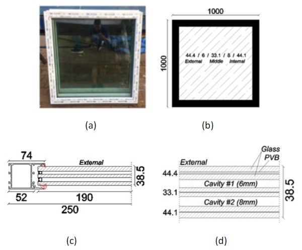
The present numerical investigation takes inspiration from (Sielicki et al. 2020), where TGU sampleshave been experimentally explored under arena blast tests.
The typical glass window, 1 × 1 m in dimension, consisted of three LG panels (0.88 × 0.88 m the net dimensions) and a polycarbonate frame to restrain them along the edges. The final result was characterized by free bending span of 0.85 m on both width and height.
Glass composition was described according to Figure 1, that is with three double LG layers composed of AN glass and PVB bonding foils (44.4 for the external side, 33.1 for the middle panel, 44.1 for the internal side). Among these LG panels, two cavity chambers with thickness of 6 mm and 8 mm respectively where realized.
3.2. Finite Element numerical model
The reference FE numerical model was developed in ABAQUS/Explicit (Simulia 2021), so as to reproduce the nominal geometrical features for the TGU sample in Figure 1.
At first, a careful attention was paid to the accuracy of results but also to the computational efficiency of numerical simulations. In this sense, the final FE assembly was obtained from a combination of shell elements, brick elements and special nodal connectors (Figure 2).
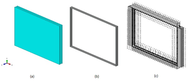
More specifically, the external and internal LG panels were described in the form of multilayer composite shell elements, by accounting for their nominal sandwich section (Figure 2(a)). The middle LG panel was described with solid brick elements. The TGU assembly was sealed along the edges by a solid brick tape (equivalent composite section in Figure 2(b)). The so enclosed unit was then restrained to a shell-based frame with the support of nodal connectors to reproduce the effect of silicone layers and gaskets (Figure 2(c)). Finally, the frame members were rigidly restrained, to reproduce their connection to the rigid concrete wall from the original experimental investigation in (Sielicki et al. 2020).
In between the glass panels of Figure 2(a), the gas cavities were taken into account via “fluid cavity interaction” option from ABAQUS library, with input calibration for the pneumatic gas law carried out as in (Bedon & Amadio 2017; Bedon & Amadio 2020).
Regarding the mechanical characterization of materials, nominal values and consolidated constitutive laws were used for the parametric study. More precisely:
- Glass: the “brittle cracking” material option from ABAQUS library was taken into account. For annealed glass, input parameters are calibrated as in (Larcher et al. 2016; Bedon et al. 2017; and others).
- PVB: an elastic-plastic constitutive law was used. For the present analysis, the input parameters for stress and strain under impulsive loads were taken from the experimental investigation reported in (Zhang et al. 2013). This input law was combined with “ductile damage” material option, to include possible tearing of interlayers after glass fracture.
- Polycarbonate: also in this case, an elastic-plastic constitutive law was used in combination with “ductile damage” option. This assumption allowed to introduce a relatively brittle failure mechanism for frame members characterized by minimum plastic capacity.
- Bonding sealant layers: in this case, a set of distributed equivalent nodal connectors is used to mechanically restrain the TGU panels to the frame (Figure 2(c)). The translational DOFs of each “cartesian” connector were set to fail after 0.5 mm of relative displacement at the interface of glassand frame. This assumption was established to allow simulating the local (if any) and progressive occurrence of failure resulting in possible fall-out of TGU from the frame installation.
The so assembled and characterized FE assembly was rigidly restrained at the external faces of polycarbonate frame, in order to take into account the actual boundary condition for an ordinary TGU window as a part of a building.
Finally, a special care was dedicated to blast loading description. All the blast configurations were numerically described with the support of CONWEP incident wave interaction from ABAQUS library (Simulia 2021). This assumption facilitated the analysis of multiple loading conditions, based on the definition of detonation point location (stand-off distance R, in m) and mass of explosive charge W(TNT equivalent, in kg). For sake of clarity in discussion of parametric numerical results, all the explored configurations are herein described as a function of the calculated scaled distance Z of blast loading (in m):

In the present investigation, the range of variation was in between 0.2 kg and 12.15 kg for the equivalent mass W of TNT, while the stand-off distance was taken in the range of 2-15 meters from the surface of the exposed glass panel. Finally, the height from ground of the detonation point was preliminary placed in line with the center of glass. Possible unsymmetrical and eccentrical detonations were excluded from this first round of simulations.
3.3 Performance indicators for blast assessment of TGU window
For the parametric analysis of TGU window under blast, the attention is focused on a list of performance indicators that should be able to describe the occurrence and propagation of failure mechanisms in the most relevant window components, namely glass panes, frame members, and bonding layers. The goal of FE simulation in blast, in general terms, is to verify the capacity of a given glass window or façade component to resist the input pressure and to prevent any kind of penetration of the blast wave in the building. While such a performance can be easily perceived and quantified from experimental investigations, more uncertainty can rely on the side of FE numerical models. In this specific study, the progressive damage evolution as a function of input blast parameters was quantified in terms of “failure time” under blast pressure for the following performance indicators (if any):
- First cracks in glass layers (external, middle, internal panels)
- First yielding of PVB foils
- First yielding of polycarbonate frame members
- Rupture of sealant layers in between the glass panels and the supporting frame•Failure of PVB foils (tearing)
- Fall-out of glass window (based on limitation of a maximum out-of-plane deflection exceeding 1/3rdthe bending span)
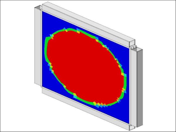
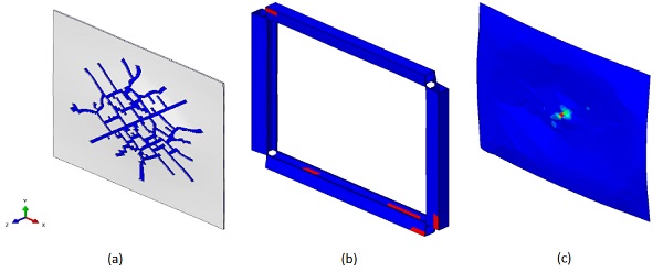
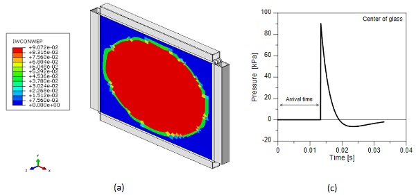
To this aim, through the dynamic Explicit simulations, careful consideration was paid for the step-by-step analysis of stress and strain trends in all the TGU components, as well as for the analysis of some relevant material indicators, such as the DUTCRT non-dimensional parameter for fracture (DUTCRT= 1 to denote full damage, or 0 for undamaged elements) and the IWCONWEP pressure parameter to monitor the propagation and evolution in time of blast waves on the exposed surfaces of glass. Finally, the behaviour of TGU system was also addressed by analysing possible variations in time for the pressure and volume (PCAV, CVOL) of the two gas cavities interposed to glass panes.
Figures 3 and 4 present some selected examples.
3.4. Selected numerical results
The quantitative analysis of TGU system under various blast loading conditions was carried out with a focus on performance parameters recalled in Section 3.3. In Figure 5, selected examples of typical dynamic responses are proposed for the TGU system underW= 6 kg and R= 8 m (Z= 4.40 m from Eq. (1)).
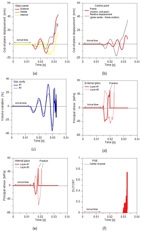
As it can be seen in Figure 5(a), the out-of-plane deflection at the center of glass panels was monitored to assess the effects of failure initiation. The presence of polycarbonate frame members in support of TGU panels was found, as also expected, to act as partially flexible linear support for glass layers. This can be seen in Figure 5(b), where the deflection at the mid-span section of frame mullions is compared with the relative out-of-plane displacement of external glass panel. The presence of gas cavities in the TGU system was typically associated to a composite bending response for the sandwich resisting section. Besides, this composite section can behave efficiently as far as the cavity boundaries are intact (i.e., glass, PVB layers, sealants at the edges).
In this regard, Figure 5(c) shows the percentage variation in time for the volume of gas cavities #1 and #2. While the original volume increases and decreases with out-of-plane bending of glass panels as in Figure 5(a), there is also clear evidence of failure occurrence. Failure in LG panels was detected on the side of glass in terms of principal stress evolution, as in Figures 5(d) and (e). Once both the glass layers in LG are cracked, plastic deformation and even fracture was observed in the interposed PVB layers, as shown in Figure 5(f).
3.5. Parametric analysis of failure trends
From the extended FE parametric study of TGU sample under various blast loading conditions, some useful feedback can be derived in terms of load-bearing capacity and residual performances expected as a function of input explosion.
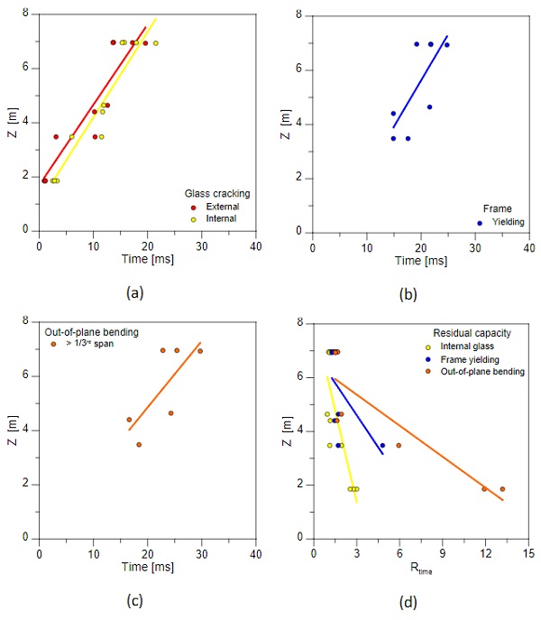
For the examined Z configurations, in the present study, glass fracture was achieved for all the glass panes, with different evolution in time. In this sense, the TGU system never offered appropriate glass strength against the input pressure. Besides, additional load-bearing capacity can be also offered by PVB interlayers, frame members and details. In this sense, Figure 6(a) shows the calculated failure time (deprived of arrival time for the blast wave) for the first crack appearance on external and internal glass panels, as a function of Z. It can be seen that the so-calculated failure time follows a rather linear trend with Z, and the scatter for external-internal interval decreases with Z increase.
For the same blast configurations, the first fracture / yielding of polycarbonate frame members is proposed in Figure 6(b). It can be seen that this happens always after glass fracture, and the failure time trend with Z is rather similar to Figure 6(a). Finally, Figure 6(c) shows the calculated failure time in terms of first exceedance of out-of-plane deflection (at the centre of window) exceeding 1/3rd of its bending span. Also in this case, bending limit condition is relatively late event, compared to others. Most importantly, the out-of-plane bending configuration is not achieved for all the tested configurations.
In this sense, Figure 6(d) shows the evolution of residual capacity that the examined TGU could offer in terms of damage evolution in principal window components. More precisely, the Rtime coefficient is used as multiplicator factor for the first glass cracking of external pane (from Figure 6(a)), and thus can be used to estimate the residual post-cracked performance of the TGU window as a whole, once the most vulnerable component (i.e., the external glass layer exposed to the incoming blast wave) is cracked. In general, for Figure 6(d), it is in fact assumed for the i-th TGU component that:

where tf,₁ is the first damage evidence (i.e., the most critical component – the external glass panel, in the present study), deprived of arrival time for blast wave.
4. Conclusions
The analysis of load-bearing capacity of Triple Glass Units (TGUs) under blast loading has been numerically explored in this paper, within the framework of GLASS-SHARD research project. As shown, the attention was focused on the numerical analysis or rather common TGU windows for ordinary buildings, but at the same time rather complex mechanical systems from a blast performance assessment point of view. Some major outcomes of a refined Finite Element (FE) numerical analysis have been thus discussed in the paper, with a special attention for the analysis of damage initiation and evolution in the principal TGU components, as well as on the definition of reliable and generalized performance indicators to quantify and assess the load-bearing capacity of blast-loaded complex glazed systems.
Acknowledgements
This activity was carried out in the framework of the research project “GLASS-SHARD – Numerical analysis of glass windows and facades under blast” (University of Trieste, 2021-2022), financially supported by Regione Friuli Venezia Giulia under the Specific Program n. 72/17 (“Voucher per la mobilità dei ricercatori nell’ambito dei centri di ricercar JRC – Programma Operativo FSE 2014-2020 della Regione Friuli Venezia Giulia”).
References
Bedon, C., Amadio, C., Enhancement of the seismic performance of multi-storey buildings by means of dissipative glazing curtain walls. Engineering Structures, 2017, 152: 320-334
Bedon, C., Amadio, C., Mechanical analysis and characterization of IGUs with different silicone sealed spacer connections -Part 2: modelling. Glass Struct Eng, 2020, 5: 327-346, https://doi.org/10.1007/s40940-020-00123-9
Bedon, C., Kalamar, R., Eliášová, M., Low velocity impact performance investigation on square hollow glass columns via full-scale experiments and Finite Element analyses. Composite Structures, 2017, 182: 311-325
Larcher, M., Arrigoni, M., Bedon, C., van Doormaal, J.C.A.M., Haberacker, G., Hüsken, G., Millon, O., Saarenheimo, A., Solomos, G., Thamie, L., Valsamos, G., Williams, A., Stolz, A., Design of Blast-Loaded Glazing Windows and Facades: A Review of Essential Requirements towards Standardization. Advances in Civil Engineering, vol. 2016, Article ID 2604232, 14 pages, 2016. https://doi.org/10.1155/2016/2604232
Larcher, M., Solomos, G., Casadei, F., Gebbeken, N., Experimental and numerical investigations of laminated glass subjected to blast loading. International Journal of Impact Engineering, 2012, 39: 42-50
Figuli, L., Papan, D., Papanova, Z., Bedon, C., Experimental mechanical analysis of traditional in-service glass windows subjected to dynamic tests and hard body impact. Smart Structures and Systems, 2021, 27(2): 365-378
Sielicki, P.W., Bedon, C., Zhang, X. Performance of TGU Windows under Explosive Loading. In: Hofreiter, L., Berezutskyi, V., Figuli, L., Zvaková, Z. (eds) Soft Target Protection. NATO Science for Peace and Security Series C: Environmental Security. Springer, Dordrecht, 2020, https://doi.org/10.1007/978-94-024-1755-5_4
Simulia, ABAQUS. ABAQUS Computer Software, Dassault Systémes: Providence, RI, USA, 2021
13:39 17/10/2022Zhang, X., Meng, Q., Bedon, C. & Sielicki, P. W., Strengthening of Laminated Glass Windows against Windborne Debris Impact. International Journal of Structural Glass and Advanced Materials Research, 2020, 4(1): 209-224, https://doi.org/10.3844/sgamrsp.2020.209.224
Zhang, X., Hao, H., Ma, G., Parametric study of laminated glass window response to blast loads. Engineering Structures, 2013, 56: 1707-1717