First presented at GPD 2017
Abstract
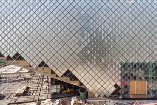
The opaque areas of the Futurium in Berlin designed by Richter Musikowski Architects are cladded with an innovative pre-fabricated rainscreen system. The smooth and shimmering homogeneous skin resembles a space ship landed next to the river Spree. The installed facade features a diagrid with pre-fabricated cassettes of 0,5 m² size combining translucent textured glass with a folded reflector on the back.
The variations of the position of reflector and screen pattern on the front of the glass lead to subtle transformations. The application of the structurally bonded, heat treated textured glass without mechanical fixings is the result of a close collaboration between all stakeholders.
The final solution of this innovative and cost-effective solution is based on extensive testing simulating ageing effects with samples simultaneously exposed to climatic influences and mechanical loads. The development of the cassette system with its sub-structure, fixing system and joint design was a complimentary process to the building design phases and showcases a successful strategy for implementing a product development approach in façade engineering.
1 Introduction
The “Futurium” designed by Richter Musikowski Architects [1] located at the River Spree will act as an international platform to bring together relevant parties and individuals from Government, Science, Industry and the Public to discuss all issues regarding the future. The project was procured by Bundesanstalt für Immobilienaufgaben as a Private Public Partnership with BAM Deutschland AG as general contractor.
Arup Deutschland was commissioned by Richter Musikowski architects during scheme design and by BAM during detail design to develop the façade solution [2]. SGS provided expert opinion [3] for the approval of the structural sealant glazing (SSG) and the structural calculation for the ventilated façades [4]. The specialist contractor for the ventilated facade was AL Promt.
The building is up to 22 m high and fully accessible by the public around its perimeter [5]. It is oriented north south with its ends creating overhangs marking the public entrances (see Figure 1).
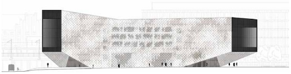
With the building mainly hosting exhibition spaces and functional rooms, the core is a monolithic concrete structure with openings cut in only for allowing access on ground floor and windows for offices located on upper floors of east and west facades. With a glazing-percentage of approx. 20% the project is representational for contemporary cultural buildings with an increasing area of opaque façade areas that reflect stringent energy efficiency codes.
Ventilated façade systems are in general the first choice to play on the opaque areas due to both the proven and robust building physics performance and high design freedom. Over the past years architects have been pushing the limitations of rain screen facade systems by exploring less regular penalization and joint patterns and introducing folded and curved panels [6]. The façade design of the Futurium presents a new development stage as it combines a visual complexity and depth with a modular ventilated façade system that allows a seamless integration of doors and windows.
2 Development of Rainscreen Cassette System
2.1 Objectives
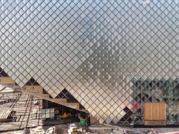
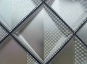
The façade design is elemental in drawing together the faceted building volume and emphasizing its sculptural effect. The strong homogenizing effect is achieved by the dia-grid penalization of the façade intersecting with the edges of the building volume and the regular small tile sizes of 0,7 m x 0,7 m. The diamond pattern extends across the entire west, south east and north east façades including areas with vision glass and soffits above the entrance areas.
The architects visual objective was to create a smooth and shimmering external skin with its individual panels transforming into radiant facets under direct sun light displaying and enforcing the changing light conditions across the day. No visible mechanical fixings should counteract the abstract geometric qualities and the joint width should be limited to max. 15mm. The bonded edges of the glass should be as invisible as possible.
2.2 Cassette System
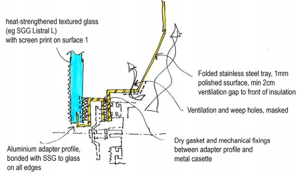
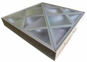
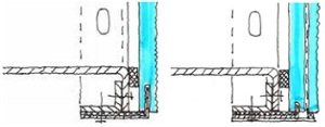
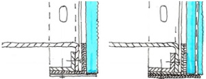
The design team developed a panelized and prefabricated cassette comprising textured glass on the outside, an adapter frame and a folded metal tray from brushed stainless steel on the back. The textured glass with its translucent and soft reflective surface features a partial white screen print on surface one. An anodised U-shaped aluminium adapter profile is continuously bonded to all edges of the glass facilitating the implementation of hidden toggle fixings for transferring wind loads to the diagrid substructure.
A grey screen print along glass edges conceals the structural silicone joints (see Figure 3). The diagonal folds in the metal tray of 1 mm polished stainless steel creates an undulated reflective surface behind the veil of the textured translucent glass capturing direct sun light and projecting it back, illuminating the glass from the back.
There are four main cassette types:
- Type 1: Standard cassettes on vertical facades (approx. 2500 m², ca. 5000 panels)
- Type 2: Cut cassettes around perimeter of vertical facades (approx. 200 m², ca. 500 panels)
- Type 3: Overhead cassettes on soffits above entrance zones (approx. 1200 m², ca. 2500 panels)
- Type 4: Cut cassettes around perimeter of soffits (approx. 100 m², ca. 400 panels)
With over 7500 regular units, the development of the cassette followed a process similar to the development of an industrial product. After the definition of the core characteristics, performance requirements and basic structural configuration the detail design emerged through a systematic investigation and evaluation of options.
From the sampling of materials over a series of mock-ups to the manufacturing of prototypes, in depth multidisciplinary technical investigations informed the decision making process. A key challenge was the fixing system and build-up of the textured glass.
2.3 Desk Study Glazing Options
To address German building regulations requiring the mechanical fixing of structurally bonded glass panels located 8 m and more above ground corresponding to ETAG Type I [7], the concept design featured hidden metal clips interlocking with the glass edges through machined grooves then known as Steindl Glassics G1 System [8]. By the time of detail design in 2014/15 Steindl had gone in arbitration and alternative procurement options were investigated:
- A: Monolithic textured glass with concealed metal clip (Type I ETAG)
- B: Laminated safety glass with textured glass on outside with metal clip (Type I ETAG)
- C: Monolithic textures glass with no mechanical restraints (Type II ETAG)
- D: Laminated safety glass with textured glass on outside with no mechanical restraints (Type II ETAG)
All options based on use of heat-strengthened glass for all plies.
2.3.1 Option A
A monolithic build-up would require the use of heat strengthened glass for upper floors to ensure sufficient post fracture integrity. The glass thickness would need to be 10 mm or 12 mm thick to accommodate the groove. Due to the limited mechanical strength of textured glass and its large tolerances of ± 1 mm the implementation of a controlled temper stress level along the grooved edges is highly questionable [9,10]. The considerable associated technical risk would require a detailed analysis of the stress levels from tempering and loading around the grooves and mechanical tests with 1:1 specimen to demonstrate a safe application affecting cost and program.
2.3.2 Option B
The metal clips interlock with a groove along the heat treated float glass of min 8 mm thickness while the front ply of the textured glass serves as pure aesthetic layer of 4 mm to 6 mm thickness. The technical risks of Option A are mitigated, however the question on the actual temper stress level along the machined edges remains requiring a series of tests and strict quality assurance during production. The textured glass should be as thin as possible to limit tolerances and reduce risk of delamination. As higher temperature levels during service can be expected, use of an Ethylenvinylacetat (EVA-) interlayer might be required as EVA unlike Polyvinylbutyral (PVB) provides a minimum shear modulus even at elevated temperatures.
2.3.2 Option C
As with Option A the textured glass would need to be heat-strengthened for upper floors, a thickness of 6 mm would be sufficient to withstand wind loads. While this principal build-up would in principle be acceptable to authorities outside Germany, the use of structurally bonded glass without mechanical fixings is in general not approved as sufficient and reliable data on the impact of mechanical and cyclic loading on the simultaneous ageing and detoriation of the structural silicon over time does not exist.
2.3.3 Option D
The use of laminated glass allows the integration of two glass surfaces with a ceramic screen print meeting the architects’ design intent. The build-up is also more robust than heat-strengthened monolithic glass.
2.4 Discussion
From a technical point of view the use of metal clips is the least favourable option. Also Option C and D allow use of thinner glass and are more cost-effective. Commercially the clips add cost of approx. 10 € per glass unit while the use of laminated glass instead of monolithic glass add approx. 30 € per glass unit. Allowing the highest architectural design flexibility and safety level, Option D was recommended based on the assumption that the long term mechanical performance of the SSG under simultaneous ageing can be demonstrated.
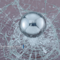
With a total length of 2,8 m structural silicone joints per panel of an area of only 0,5 m² the risk of a complete failure of the silicone seal leading to the drop of a panel is low, however authorities asked for experimental evidence. Standard ageing tests according to ETAG 002 had to be combined with mechanical loading representing the expected service loads during life time of 30 years [7, 11, 12].
3 Thermal Study (Arup)
3.1 Objectives
A specific issue of the cassette design was the heat build-up in the cavity. The temperature levels inside the cassette not only influence mechanical loading due to thermal expansion as a key parameter for ageing effects, but also impact on durability of laminated potentially glass due to delamination. In order to assess the maximum temperature the laminated glass could be exposed to and associated risk of delamination a dynamic thermal analysis has been carried out.
The following build-up of the cassette was assumed:
- 4 mm textured glass laminated with 6 mm float glass (Energy transmittance: 73% / Energy Absorption: 20%). Approximately 50% of the surface of the glass present fritted dots, white on the front and silver on the back.
- 20 mm cavity
- Highly reflective steel panel (Reflectivity: 55% / Absorptivity: 45%)
- Ventilation
- Insulation
Because of the high transparency of the textured glass, most of the incident solar radiation will be absorbed by the steel back panel. Even if the steel panel can reflect most of the incident solar radiation, the limited air velocity of the back ventilation can lead to a significant overheating of the back ventilated façade and to possible delamination of the external glazing.
As the maximum temperature is determined by the mutual effect of the external air temperature and the infrared radiation due to the absorption of the solar radiation by the steel back panel the aims of the analysis were:
- Calculate the maximum solar radiation on the different façade orientations, taking into consideration the shading effect of the surrounding buildings.
- Calculate the temperature distribution in the build-up of the back-ventilated façade for the worst case scenarios of maximum solar radiation.
- Recommend suitable interlayer material.
3.2 Method
The analysis has been carried out for the west, north-east and south-east facades featuring the ventilated façade system. The analysis has been carried out with EnergyPlus 8.4, based on a sketch-Up 3D-Model [13]. The temperature distribution within the façade build-up has been calculated with the software WIS 3.01 SP2 [14]. The 3D-Model included also the volumes of the surrounding buildings, in order to evaluate their shading effect.
3.3 Results
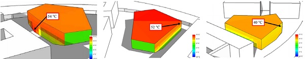
The results of the analysis confirm that the temperature of the façade construction is the results of the mutual effect of the external air temperature and the incident solar radiation, absorbed by the steel back panel. However, since the peaks of incident solar radiation occurs when the air temperature is relatively low and most of the radiation can be reflected by the steel back panel, the worst-case scenarios are represented by the hours of the year when the maximum air temperature is reached.
In particular, on the South-East façade the peak solar radiation reaches 925 W/m² at the beginning of April, when the air temperature do not exceed 20°C. However, in the middle of June an external air temperature of 28°C, together with a peak incident solar radiation of approximately 720 W/m², heat up the steel back panel to a surface temperature of 54°C. Because of the air movement in the cavity between laminated glass and back panel, the glass will reach a maximum temperature of 42°C.
The temperatures of the glass calculated in the other analysed façade faces never exceed 40°C.
As standard PVB-interlayer can resist up to a temperature of 60°C with sufficient mechanical properties it’s use for this application would not be critical with respect to risk of delamination, however use of EVA was specified.
4 Examination of durability under complex loading
4.1 General
The vertical façades of the Futurium are Type II structural sealant glazing systems. The individual glazings have mechanical supports for the transfer of the dead load but do not have any mechanical fixings or retaining devices, which could hold the glass in place in case of failure of the structural sealant.
Although the cassettes in the horizontal overhead areas have retaining devices, the self-weight of the glazing must be transferred to the sub-structure by the SSG joint only. This corresponds to a type IV glazing according to ETAG 002 [7]. The glazing consists of laminated glass with EVA. Since only the inner panes are supported by the SSG joint and retaining devices are only located in the horizontal areas, the outer panes of the laminated glass are only supported by the intermediate EVA layer. Here, only the experimental investigations with respect to the durability of the SSG joints simultaneously exposed to climatic influences and mechanical loads are described in detail.
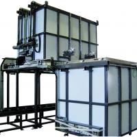
4.1 Test procedure
To investigate the durability of the SSG joint a multistep verification method was used, which was developed within the framework of a research project [11, 12]. In contrast to the previously harmonized European method by ETAG 002 [13], in which different influences on the durability and the mechanical strength are examined separately, mechanical, climatic and chemical influences are tested in combination.
For the applied verification method, a representative system sample is subjected to a cyclic mechanical test under changing climatic conditions. The representative system sample consists out of a stainless steel profile, a glass pane and the SSG joint. The materials of these parts are the identical materials which are used for the façades of the Futurium. The length of the steel profile and the SSG joint is 400 mm.
The glass pane has a width of 245 mm and a length of 400 mm. The SSG joint (6 mm x 12 mm) was arranged at the edge of the stainless steel profile. In the tests, two representative system samples were tested. Both samples could be fixed next to each other in the tests setup and could be tested simultaneously. In addition, one sample was added to the tests, which was exposed only to the climatic and chemical influences.
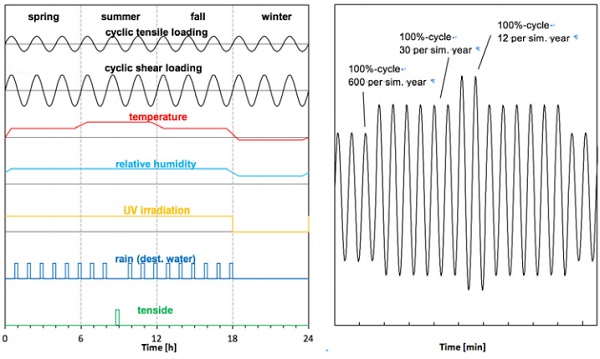
In the experiment, one year in service is simulated in one experimental day [12]. In order to simulate the usual service life for buildings of 50 years, the experiments are carried out over a period of 50 days. The simulated year is divided into four periods according to the seasons, in which different climatic loadings are applied simultaneously with a cyclic mechanical load. In Figure 9, the schematic representation of the loading of a experimental simulated year is shown.
The temperature loading was defined according to the thermal simulation [2] presented in section 3 and according to EN 1991-5 [15]. The maximum temperature during the simulated summer was set to T = 60°C, during the simulated winter to T = -20°C. Additionally, the samples were periodically sprinkled with distilled water to simulate rain events and irradiated with a power of 20 W/ m2 in the simulated seasons spring, summer and fall. For one rain event per year instead of distilled water a tenside solution was used as chemical load of the sample [11, 12].
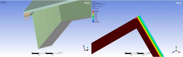
The applied cyclic tensile and shear loading of the durability test was defined by a detailed finite element calculation, wherein the cassette was modelled in full detail with volume elements and loads from self-weight, wind (suction, pressure) and temperature (summer, winter) were investigated. According to these calculations, the maximum shear deformation was set to 1.14 mm and the maximum tensile deformation to 0.30 mm for the deformation controlled tests. These values include both full design loads as well as an increase by a factor of 2.14 by which the small sample size is considered.
For the evaluation of the material strength, the material properties of the SSG joint in the initial state and in the final state after complex loading were investigated by tests as defined in ETAG 002 [7].
4.3 Results
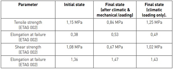
Both test specimens subjected to the durability test with complex loading have passed the test. However, during the experiments a reduction of the resulting force could be determined in tensile direction as well as in shear direction. This decrease in stiffness of the SSG joint can be attributed to microscopical material detoriation and the Mullins effect. In Table 1, a comparison of the strength and elongation values of tensile and shear tests according to ETAG 002 [7] in initial and final state is given. The increasing elongation at failure proves the decrease in stiffness.
The strength values in final state are lower than in initial state. Nevertheless, the design strength values determined from the strength test in the final state after complex loading with a partial safety factor of 6 are sufficient to transfer the loads acting on the façades [4]. The ratio between technical stresses from loading and technical strength after ageing is about 15%.
5 Conclusions
The cassette design with clearly defined mechanical interfaces based on a single design basis for over 7500 panels, still enabling a large degree of freedom and flexibility for aesthetics could be achieved. This approach required an in-depth technical analysis for optimizing the system design and glass configuration leading to cost savings in the final design.
The durability of the SSG joints for the façade of the Futurium was tested by a new testing method [11, 12], in which climatic influences and mechanical loads act cyclically and simultaneously on large scale samples to simulate the service life for a defined time period. The test results shows that the SSG joints in this project could be classified as sufficiently durable regarding a simulated service life of 50 years.
For usual building projects, the new test method seems to be too time consuming and complex to be applied each time. Nevertheless, further scientific research and experiments should be carried out in order to compare the results with cyclic fatigue tests for different load levels, boundary conditions and climatic influences to study the detoriation and failure mechanisms of SSG joints systematically.
6 References
[1] http://www.richtermusikowski.com/kultur/hausder-zukunft-berlin/
[2] Arup Deutschland GmbH: „Haus der Zukunft – Variantenbewertung Fassade, Rev C”, 21st June, 2015
[3] SGS Ingenieurdienstleistungen im Bauwesen GmbH: Gutachterliche Stellungnahme 1118/2015.15.03 zur Structural Glazing Fassade BV Haus der Zukunft“, Heusenstamm, May 2nd, 2017
[4] SGS Ingenieurdienstleistungen im Bauwesen GmbH: „Statische Berechnung 1147/2016.22.01 der Fassadenkonstruktion des BV Haus der Zukunft, Berlin“, Heusenstamm, September 27th, 2016.
[5] https://www.futurium.de/[6] http://www.fvhf.de/Fassade-bilder/docs/Prospekte/FVHF_Doku_Fassadenpreis_2013.pdf
[7] EOTA, ETAG 002: Guideline for European technical approval of Structural Sealant Glazing Kits (SSGK), June 2013
[8] European Technical Approval Steindl Glassics G1 (ETA - 08/0099), 13th May 2013
[9] DIN EN 572-5: Glass in building. Basic soda lime silicate glass products. Patterned glass, July 2012
[10] Schneider J., Hof P., Block, C.: Fastening of Glass Panes with Undercut Anchors. Numerical tempering simulation, experiments, load-bearing capacity. Proceedings of the 2nd International Colloquium on Modelling of Glass Forming and Tempering (M.G.F.T.), University of Valenciennes, France, 23.01.-25.01.2002, pp. 247-254
[11] Bundesanstalt für Materialforschung und -prüfung (BAM): „Schlussbericht zum MNPQ Projekt 22/10 ‚Entwicklung und Validierung einer innovativen, qualitätsgesicherten Befestigungstechnologie für Glasfassaden mit Hilfe eines neuartigen Untersuchungsverfahrens“, Berlin, June 30th, 2015
[12] Recknagel, C.: Potential of Dynamic-Mechanical Analysis Toward a Complementary Material and System Testing Approach for Structural Glazing,” Journal of ASTM International, Vol. 9, No. 4, 2012, pp. 1-17
[13] EnergyPlus 8.4.0, Release September 30th 2015
[14] Window Information System (WIS) version 3.0.1 with service pack SP2, Release October 2006
[15] EN 1991-1-5: Eurocode 1: Actions on structures - Part 1-5: General actions - Thermal actions
8 Acknowledgements
Michael Vahlert (Partnerschaften Deutschland); Jan Musikowski, Christoph Richter, Sebastian Haufe (Richter Musikowski Architekten); Andreas Jorsch, Ralf Rykarski (BAM Deutschland); Christoph Recknagel (Bundesanstalt für Materialforschung und -prüfung); Alexander Morgenroth (SteindlGlas); Charlotte Heesbeen, Frank Walter, Dirk Regenspurger (Arup Deutschland GmbH)