Source:
Challenging Glass 7
Conference on Architectural and Structural Applications of Glass
Belis, Bos & Louter (Eds.), Ghent University, September 2020.
Copyright © with the authors. All rights reserved.
ISBN 978-94-6366-296-3, https://doi.org/10.7480/cgc.7.4765
Authors:
John Kooymans - Read Jones Christoffersen Ltd, Canada
Andrew Crosby - Read Jones Christoffersen Ltd, Canada
Dr. Jens Schneider - TU Darmstadt, Germany

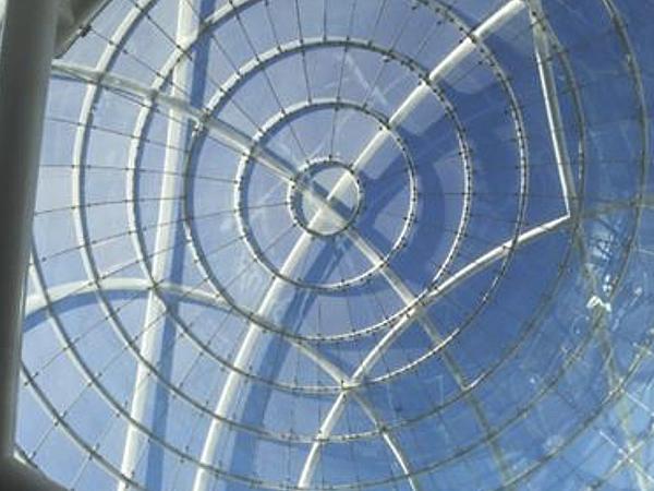
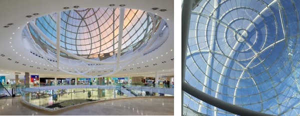
Erin Mills Town Centre is a shopping mall in Mississauga, Canada owned by Cushman & Wakefield in Toronto. The revitalization project was designed by MMC International Architects Ltd. and features a 27.4m diameter glass and steel globe at its Centre Court. The structural glass for this globe structure is created with laminated double curved glass panels patch supported by a steel structure.
Some challenges arose during construction due to the frit on the glass panel and the thermal stress created between the inner and outer lites of the laminated assembly. Testing was used to establish a workable solution for replacement glass in order to correct the in-situ issue that was discovered.
1.Introduction
Cushman & Wakefield were looking to revitalize the existing Erin Mills Town Centre shopping centre in Mississauga, Ontario, Canada. The architectural design team lead by Chris Brown of MMC International Architects Ltd. challenged our office to create a unique glass and steel feature element at the Centre Court of the mall. Several options were provided for Ownership review, and the structural globe was chosen.
The globe glass is patch supported to a series of steel rings (similar to lines of latitude on the globe) which in turn are supported by seven random steel rings. The globe structure was also constructed on a 23.5 degree tilt to represent the angle of the Earth’s axis. The glass panels for this project were to be constructed of three layers of double curved glass. A ceramic frit was applied to surface #2 of the lamination, and a hard coat low-e coating was applied to surface #6 in an effort to provide some comfort to the occupants in summer conditions.
The original design proposed point supported glass panels with fully tempered or heat-strengthened panels. This proved to be difficult to achieve as described in this paper, and the decision was made to change to patch fittings with annealed glass panels. The design loads and stress levels were low enough to allow for this type of construction, however, the thermal stresses resulting from the geometry of the structure created a load condition not envisioned and corrective measures were necessary.
2.Design Concept
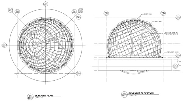
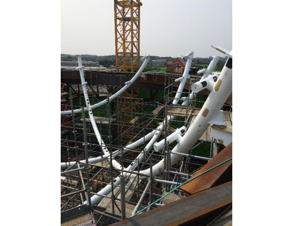
Figure 1 below shows the steel structure for the supporting globe glass panels. We have taken seven random rings that intersect with each other to create a support structure for the evenly spaced rings creating the globe shape and supporting the glass panels. The seven rings support the entire structure globally and bear on brackets off the stiffened roof structure (see Figure 2) that creates the centre court opening. All steel is an exoskeleton structure with the glass panels hung off of it to create a very smooth glass surface on the inside of the building space. This was done to help facilitate air movement along the interior glass surface and keep this movement as evenly spread as possible.
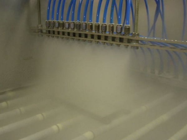
The glass panels are laminated for strength and safety. Since the panels are monolithic, a significant mechanical system was installed with blowing jets all around the base of the globe structure to ensure good air movement and help cool the space and glass in the summer months. The glass was designed with a low-e coating and a ceramic frit pattern to assist in controlling the solar heat gain as well. The original concept was to hang the glass panels off the steel structure with point supported spider connectors. This would require tempered glass and some creativity in manufacturing this glass in double curvature.
3.Double Curved Glass Options
As mentioned previously, the first glass make-up consisted of tempered glass. Originally, the design called for three layers of 6 mm glass laminated with 1.52 mm SentryGlas interlayers. This design concept evolved into a 5 mm fully tempered lite/10 mm chemically tempered lite/5 mm fully tempered lite. The panel was constructed by slumping the 10 mm thick glass into the proper double curved shape and then chemically tempering it. This created the shape for the outer and inner 5mm fully tempered flat lites to get laminated to and held in place via the strong interlayer. Acceleration tests were carried out under high humidity to see if the lamination would hold over the lifespan of the glass assembly.
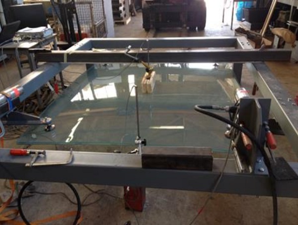
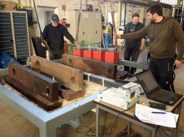
In addition to the test assembly and adhesion testing, load/strength tests were carried out at the Laboratory for Steel and Lightweight Metal Construction of Munich University and Applied Sciences in Munich, Germany. The Figures 3 and 4 below show some of the test procedures done on the larger size panel.
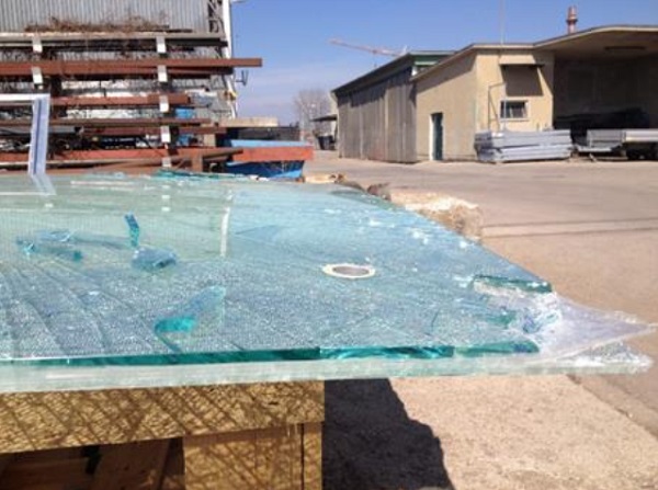
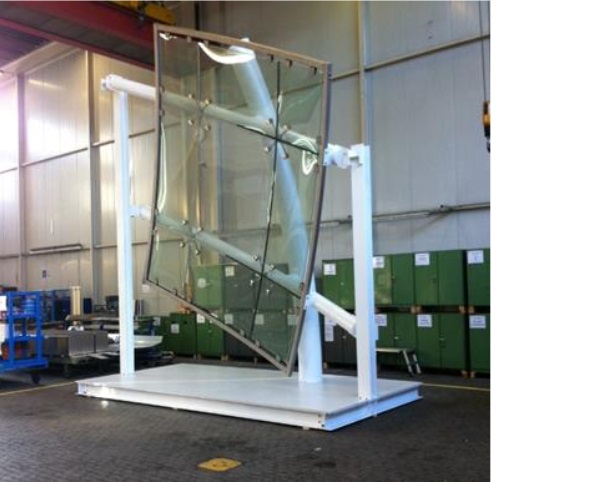
The strength tests and the accelerated adhesion tests all performed well, however, we did have issues with consistency of the assembly and visual imperfections. The Figures 5 and 6 below show these delamination problems (especially after breakage of one lite), and the optical anisotropies/visual distortions inherent in the process.
As a result of the issues found in the load tests and the mock-up, it was decided that the assembly would look much better if all three lites were heat slumped annealed glass with the outer lite still having a frit on surface #2 and the inner lite having ahard coat low-e coating on surface #6. It meant revising the fastening system from a point support spider connector to a patch fitted spider connector. Going to the annealed glass, the assembly was revised to three equal lites of 8 mm thick.
4.Thermal Stress Issues
The fabrication and erection of the glass panels proceeded based on the results of new FE models for strength and stress calculations. Thermal loading was modelled due to the shadows created by the exoskeleton structure on the glass and were found to be within allowable limits. During construction, however, the contractor (Josef Gartner GmbH) noted several panels were cracking. After reviewing the fracture patterns of the cracked glass, it was determined that most were failing due to excessive thermal stress within the outer fritted lite. A reduction of glass strength was already used for the fritted glass (40% reduction) in the analysis of the revised assembly, so further investigation was required to establish the cause.
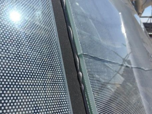
Upon closer examination, it was noted that all the thermal stress cracks originated at a frit dot location. As shown in the Figures below, this was consistent in all panels that cracked. We started to understand where the problem was, but needed a way to find an appropriate solution that we could be confident in. RJC hired Dr. Jens Schneider at this time to review the issue at hand and devise a test that would allow us to establish the cause and to then recommend a solution to the problem.
Information gathering was first implemented. Site readings of the glass surface temperatures on the interior and exterior were taken during the summer months so that we could determine the thermal gradient from inside to outside of the laminated assembly. Readings were taken at several locations every 15 minutes.
The results of the temperature readings showed that the interior ambient temperature and exterior ambient temperatures were within 5 °C of each other in the summer, however, the surface temperatures were significantly different. Surface #1 (exterior) was in the range of 35 °C while surface #6 (interior) was in the range of 55°C. This yielded a differential temperature in the worst conditions of approximately 20 °C through the cross-section of the laminated glass panel.
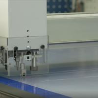
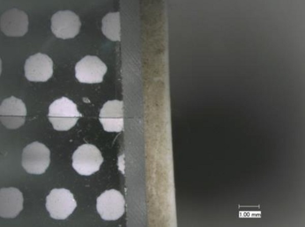
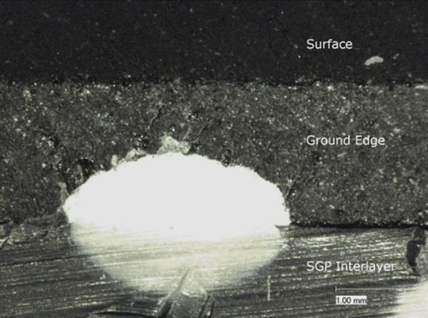
Additional information was gathered by taking samples (see Figure 9) of the in-situ glass by cutting out a section at the location where the thermal crack initiated. These were catalogued and taken back to the labs at TU Darmstadt.
The microscopic image below shows the frit taken right to the edges of the glass including the chamfered edge. It was becoming obvious that this was an issue and causing premature failures of the assembly. In addition, the specimens taken from site were opened up at the crack line to examine the fracture patterns and evaluate potential causes. These examinations also confirmed that the issues arose at the frit location directly at the edges of the glass panels.
5.Testing Procedures/Results
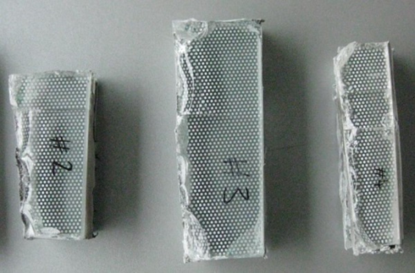
The next step was to obtain samples of the glass used in the laminated glass assembly for further strength testing and to see how the manufactured glass compared to the allowable stress levels we were using in our design simulations. Four Point bending tests and Double Ring bending tests were used to establish these strength levels.
The test samples were categorized into five different series. The Four Point bending test was used on the first four series of specimens and the Double Ring test was used on the fifth series. These are summarized in the Table below.
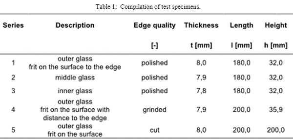
Series 1-3 are test specimens cut out of the edges of the three different glass panels which would be typically used in the laminated assembly. The only difference with these samples is that they were produced with polished edges instead of ground edges as per the in-situ panels previously supplied to the site.
Series 4 are test specimens cut out of the edges of a fritted glass panel that had the frit edge deleted a distance from the edge of the panel. The actual specimens in this series do not have any frit on the cut out sample and had a ground edge preparation.
Series 5 are test specimens with a frit over the entire surface. The specimens were cut from the center of the glass panel for surface stress testing.
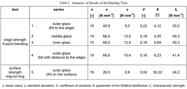
FE models were also performed to get an understanding of the stress levels we may expect from the gradient temperature difference throughout the thickness of the glass assembly. This was carried out for a thermal gradient of 20 °C based on in-situ monitoring. From the results of these specimen test sand the FE models, it was determined that the glass assembly should be okay for the climatic loads and the thermal stress loads provided the frit is held back from the edge of the glass panel and the gradient is 20 °C or less. It was also noted that the glass strength at the edges of the panels with frit extended to the edge was actually closer to 40% of the non-fritted glass value vs. the 60% assumed in the original calculations.
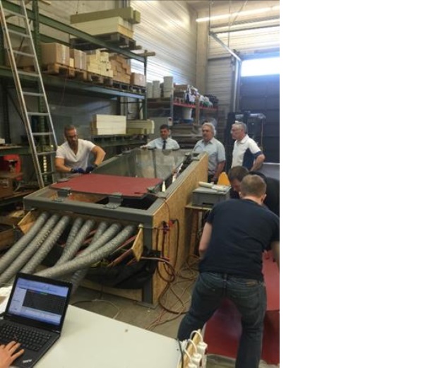
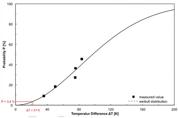
To further satisfy that the new glass assembly utilizing an edge deletion of frit of 10 cm from the edge of the panel could resist the thermal stresses anticipated, additional testing was done on full size specimens to see what thermal gradient would produce a stress failure in the panel (See Figures 11 and 12). This test was used to confirm that the thermal gradient anticipated on site would fall within a safe zone for the actual capacity of the glass assembly.
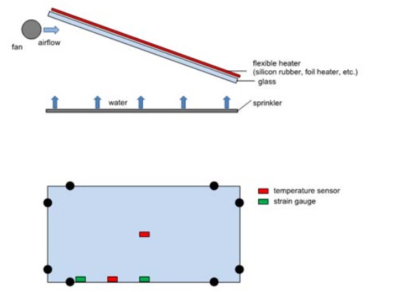
The test was carried out using three different assemblies. Series 1 was as per the in-situ panels (frit to the edge of the glass). Series 2 had an edge deletion of 10 cm, while series 3 had no frit at all. The tests resulted in a probability of failure curve as shown below in Figure 13 for the series 1 specimens. Series 2 and 3 could not be graphed in a similar manner since the glass specimens only broke due to in plane thermal stress due to the test setup and did not break due to the thermal gradient between surface #1 and surface #6.
6.Conclusions
Through all the testing and FE models performed, the following was concluded:
- That the edge strength of the annealed glass panels with no frit, or with the frit held back from the edge is essentially the same and that this value is slightly higher than the ASTM standard values.
- That the edge strength ofthe annealed glass panels with frit to the edge is lower than anticipated and lower than the ASTM standard values using a 40% reduction in capacity due to the frit.
- That the surface strength of the annealed glass panel with frit is slightly higher than the ASTM standard values using a 40% reduction in capacity due to the frit.
- If we edge delete the frit and polish the edges of the glass panel to achieve the highest quality edge treatment possible, the glass will safely withstand the thermal loads expected under its service life.
7.Acknowledgments
Read Jones Christoffersen Ltd. would like to acknowledge the Ownership (Cushman & Wakefield) for their cooperation in designing a unique glass structure for the Erin Mills Town Centre project. We would also like to thank Joseph Gartner for their expertise and assistance and Dr. Jens Schneider along with the team at TU Darmstadt for all their guidance in ensuring the project’s success.