Article Information
- Digital Object Identifier (DOI): 10.47982/cgc.8.410
- This article is part of the Challenging Glass Conference Proceedings, Volume 8, 2022, Belis, Bos & Louter (Eds.)
- Published by Challenging Glass, on behalf of the author(s), at Stichting OpenAccess Platforms
- This article is licensed under a Creative Commons Attribution 4.0 International License (CC BY 4.0)
- Copyright © 2022 with the author(s)
Authors:
- Rozemarijn Veenstra - Structural Design & Building Engineering, Faculty of Civil Engineering & Geosciences, TU Delft
- Chris Noteboom - Structural Design & Building Engineering, Faculty of Civil Engineering & Geosciences, TU Delft
- Faidra Oikonomopoulou - Department of Architectural Engineering + Technology, Faculty of Architecture and the Built Environment, TU Delft
- Mauro Overend - Department of Architectural Engineering + Technology, Faculty of Architecture and the Built Environment, TU Delft

Abstract
This research revolves around the design, fabrication and testing of tubular glass columns, with particular focus on their redundancy and fire-safety mechanisms; moreover, addressing aspects such as: the column shape; cleaning and maintenance; end connections; geometric tolerances in the glassand demountability. Two alternative circular hollow (tube) column designs are initially developed and engineered to address these aspects, namely: the MLA (Multi Layered with Air) and the SLW (Single Layered with water). In both concepts the main load-bearing structure consists of two concentric laminated glass tubes.
Thus, in order to explore the manufacturing challenges and structural potential of these concepts, the prototyping and experimental work focuses on six 300 mm long samples with 115 mm outer diameter that are laminated and fitted into customized, engineered steel end-connections. Particular attention in terms of manufacturing is paid to the lamination process and associated bubble formation, the possible fracture of the glass by internal resin-curing stresses and the interface between the glass tube and the steel end-connections. All samples are laminated with Ködistruct LG 2-PU component.
Three samples are assembled using DURAN® (annealed) glass and the other three are using DURATAN® (heat-strengthened) glass. Subsequently, t he six samples are tested in compression until failure to investigate the behaviour of the interlayer material, the post-fracture behaviour of the designs, the differences between annealed and heat-strengthened samples, the capacity of the glass tubes and the performance of the end connections. Initial cracks appeared between 95-160 kN (compression strength of 30-50 MPa) in the DURAN® samples and between 120-160 kN (compression strength of 37-50 MPa) in the DURATAN® samples.
These loads are lower than the ones estimated by calculations; in specific, the first cracks occurred at 34-64% of the calculated load. Nevertheless, the samples are found to be robust, with a considerable load-bearing capacity beyond the first cracks, leading to a maximum nominal compression strength capacity of up to 152 MPa for the DURATAN® samples and up to 233 MPa for the DURAN® samples.
1. Introduction
1.1. Problem introduction
The high compressive strength of glass makes it ideally suited for compression members such as columns. Glass columns are a particularly promising application, because their transparency also allows for space continuity and better daylight penetration in indoor spaces. However, they have been rarely applied in practice, due to multiple reasons, namely: a lack of sufficient strength data and building guidelines, uncertain variables, costs, complications with manufacturing, poor fire resistance, low tensile strength, and glass’s brittle nature and spontaneous failure (Kalamar et al. 2016) (Oikonomopoulou et al. 2017).
According to Nijsse and Ten Brincke (2014), there are five types of all glass columns: profiled, layered tubular, bundled, cast and stacked. Oikonomopoulou et al. (2017) presents an extensive overview of the experimental work conducted so far on the different types of all-glass columns and states that, at present, the only free-standing structural glass column applied in buildings, is the profiled glass columnwith a cruciform cross-section. Nevertheless, a closed, tubular, profiled column presents considerablybetter (torsional) buckling resistance; moreover, due to its lack of angles and edges it is less susceptible to accidental impact (Eekhout 2019) and can be visually perceived as less intrusive.
Although some experimental research has been conducted on glass tubes by Achenbach and Jung(2003), Doenitz et al. (2003) and Overend et al. (2005), there are not yet well-established manufacturing methods with related checking and calculation methods for this efficient-shaped glass column type. Despite the lack of existing examples of glass-tube columns, glass tubes have been previously structurally applied in tensegrity structures (Achenbach and Jung 2003), in the façade of the atrium of the Tower Place in London (Doenitz et al. 2003) and in a zip truss beam that demonstrates tension and compression by colours lighting up in the glass tubes (Glass & Swinging Structures bv. 2021).
Van Nieuwenhuijzen et al. (2005) and Veer and Pastunink (1991) previously developed a laminated glass column made of two concentric glass tubes. According to Van Nieuwenhuijzen et al. (2005), the main challenges evolved around lamination due to the adhesive’s shrinkage and the dimensional intolerances of the glass tubes. Hence, more knowledge is needed towards realizing this type of glass column, particularly on its manufacturing processes, fire safety mechanisms, and robustness. Thus, the main objective of this research is to design and engineer a transparent, tubular glass column which is load-bearing, redundant, robust and fireproof.
1.2. Methodology
This paper presents the design, engineering and experimental testing of tubular glass columns. First, design criteria are established on fire-safety, redundancy, manufacturing and replaceability. Secondly, two alternative design concepts with different fire-safety strategies are developed; emphasis is also given in the design of the end connections. In both concepts the load-bearing element of the column consists of two concentric tubes that are bonded together with an intermediate material. Following,the experimental work focuses on the production and testing under compression of six small-scale prototypes made of two laminated concentric tubes. The tested samples are made of either annealed (DURAN® - 3 samples) or heat-strengthened glass tubes (DURATAN® - 3 samples), mainly to observe the possible fracture of the glass by internal resin-curing stresses and to observe the differences in failure. Manufacturability, load-bearing capacity, robustness and post-breakage performance are explored.
1.3. Redundancy and fire-performance: Design criteria and strategies
According to Honfi and Overend (2013), there are three levels of redundancy in glass structures: material, component and structural system. To improve component redundancy, heat-strengthened glass is preferred over annealed glass (Oikonomopoulou 2019), due to its increased tensile strength and post-breakage residual capacity when laminated. This also improves fire resistance.
Relevant performance criteria of fire-resistant glass are: integrity, insultation, and radiation (Gravit et al. 2019). To improve the thermal-resistance of the glass column borosilicate glass is preferred. This is due to its considerably lower coefficient of thermal expansion compared to soda-lime glass, which results in a higher resistance to thermal shock (e.g. borosilicate glass is typically used in laboratoryware for this reason). An interesting solution in terms of insulation, is by filling the glass tubes with water to maintain the glass cool. This concept was introduced for the columns of the Samsung Museum in Seoul in Korea; unfortunately, due to the collapse of the Korean economy the project was not realized (Nijsse 2003).
1.4. End-connections: Design criteria and main concerns
For the design of the end connections, the following aspects are taken into account:
- Hinged connections, so that the column will only take up normal forces.
- Uniform introduction of forces in the glass to avoid local peak stresses.
- Replaceable column design when partly or completely broken. In case of breakage a temporary structures is needed until the column is replaced.
1.5. Manufacturing considerations
Given that the column needs to be sealed to avoid dirt coming into the column, the glass tube becomes a closed cavity. Isochoric pressures occur due to temperature differences between the inside and the outside of the column. Eventually, these pressures could result in condensation. During the heating-up of the lamination process thermal stresses will occur due to the different thermal expansion coefficients of the glass and the interlayer material. Moreover, due to the geometric tolerances in the glass, differences in thickness in the interlayer material occur. The thicker the interlayer, the more stress resulting on the glass during and/or after curing. If the interlayer becomes too thin, structural integrity is not guaranteed.
2. Design concepts
All of the abovementioned criteria and concerns are considered carefully and lead to the two concept designs as follows:
- (MLA): a Multi Layered with Air glass column, with and without a ventilation system
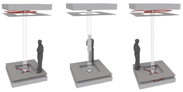
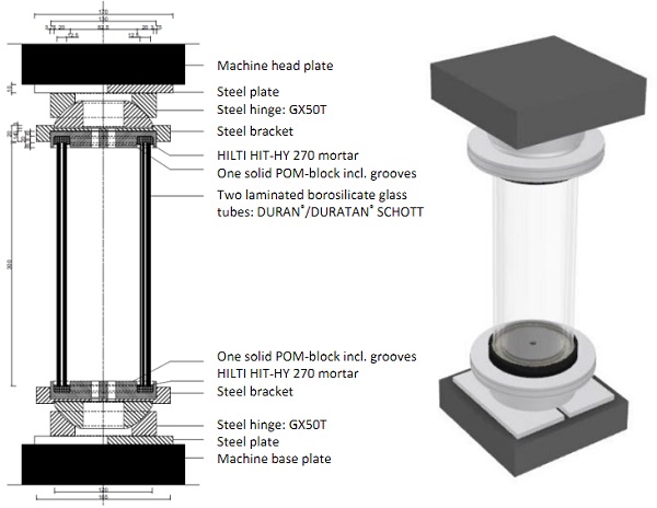
- (SLW): a Single Layered with Water glass column. Figure 1 shows a characteristic cross-section of the two concepts.
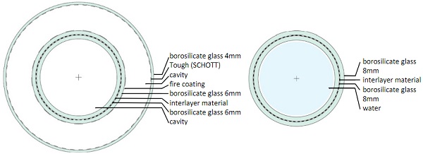
2.1. MLA column
The MLA column (figure 1, left) consist of an outer, non-load bearing tube and two inner load-bearing borosilicate glass tubes. The outer glass tube has a polymer coating on its inner surface and its primary purpose is to protect the inner glass layers. The two inner, load-bearing, tubes are bonded together by a transparent interlayer material. In this project, Ködistruct LG, LOCA material from H.B.Fuller Kӧmmerling is used. This is a thermoset liquid resin, formed with cross-linked polymers. The first component is polyol and the second is isocyanate.
This interlayer material cures at room temperature. Due to this, no sudden cooling takes place, whereby no extreme stresses occur. Furthermore, this interlayer material has a low shrinkage value (3.5%) resulting in smaller quantities of entrapped air (e.g. bubbles) and low residual stresses within the adhesive layer. The outer surface of the middle layer will be coated with a transparent fire resistance coating (e.g. HCA-TR)1. This coating is protected from scratches by the outer glass tube. It is further advisable to use sprinklers in the building, in order to reduce the temperature of the glass for a prescribed duration in the event of a fire.
1 It should be noted that this coating has been only tested on flat glass panels and more research is needed for the application of glass tubes.
As mentioned before, temperature differences between the closed glass tube cavity and the exteriorcould result in air pressure that in turn can result in condensation and stresses. If the glass columncannot resist these stresses, the air pressure can be regulated by a ventilation system. Nevertheless, condensation could still occur. Therefore, silica desiccant grains are included in the design, in a similar manner to desiccant commonly used in insulating glazing units. Figure 2 (left and middle) shows the MLA with and without a ventilation system.
2.2. SLW Column
The SLW glass column (figure 1, right) comprises two glass tubes bonded together by an interlayer material (the same liquid resin as used for the MLA). In this concept, the tube is filled with water to keep the glass cool in the event of a fire. The water will be pumped through the column. As in the MLA variant, it is advisable to also use sprinklers in the building to further reduce the temperature of glass if needed. The 3D-view of SLW is shown in figure 2 (right).
To resist the resulting thermal stresses and reduce condensation risk, filtered air is supplied via a ventilation system, or water will be regulated, or silica grains are included in the design. Stresses occurring due to the lamination process need to be checked in the experimental investigations.
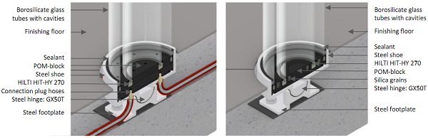
2.3. Design of end-connections
In both designs, hinged connections are used, to ensure that only axial compression forces aretransmitted to the glass column. A POM-block is placed in between the steel shoe and the glass tubes, because it has a lower Young’s modulus than glass. Hilti mortar will be injected under the glass tubes into the groove of the POM-block to distribute the compression loads from the connection into the glass tubes. The POM-block can accommodate several variants of the glass columns e.g. the application: water, air or silica grains. Figure 3 shows two different 3D cross-sections of the end connection from the MLA.
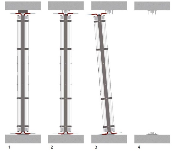
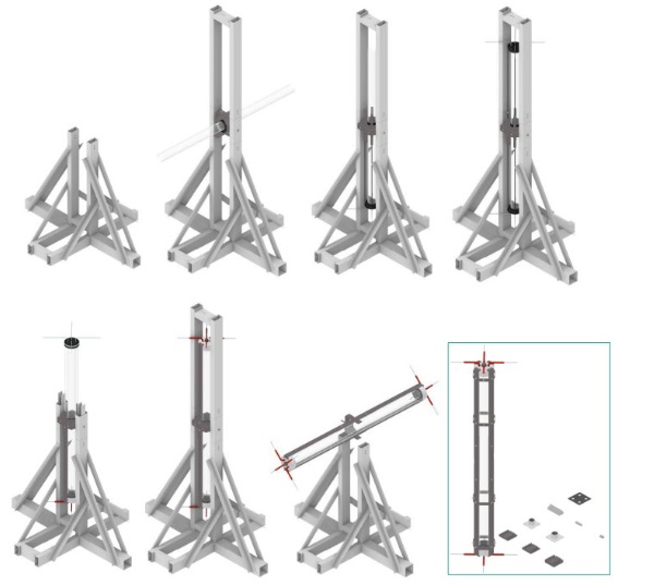
A few steps of the assembly sequence are shown in figure 5. Environmental sustainability is considered by designing for demountability. The glass column can be removed from the building in one piece. To achieve this, dry connections are used, so all components can be reused as well2. In this way, it is also possible to replace the column when broken (figure 4). Temporary struts need to be placed on either side of the broken column, and the column can removed and replaced.
2 Except for the Hilti mortar which is not reusable; delamination of the glass tubes is also not considered possible.
3. Manufacturing of the small-scale prototypes
In both design concepts, the load-bearing glass structure consists of two glass tubes that are bonded together via an interlayer material. This part is considered as the most crucial in terms of manufacturing, as it involves the bonding of the two glass tubes together. To investigate both the structural potential and manufacturing challenges of the developed concepts, t he experimental work focuses on the manufacturing and testing of 6 small-scale glass prototypes of 300 mm length and 115 mm outer diameter. These samples are made of two glass tubes that are bonded with an interlayer material.
The process of lamination is sensitive because it affects bubble formation and possible breakage of the glass caused by shrinkage stresses. The prototypes are laminated by H.B.Fuller Kӧmmerling and tested in compression at the Stevin lab II at the Technical University of Delft, to investigate the behaviour of the interlayer material, the post-failure response of the designs, the differences between annealed and heat-strengthened glass samples, the behaviour of the connections under pressure, and the capacity of the glass tubes and the connections.
3.1. Small-scale prototype layout
Each sample consists of two glass tubes. The diameter of the outer tube is 115 mm, the wall thickness is 5 mm, and the length is 300 mm. The diameter of the inner tube is 100 mm, the wall thickness is 5 mm, and the length is 300 mm. This gives a cavity of circa 2.5 mm between the two glass tubes. Figure 6 shows an illustration of the samples. From the 6 samples, the first three samples are made of DURAN® (annealed) glass tubes, and the other three samples using DURATAN® (heat-strengthened) glass tubes.
Ιn all samples the end-connections are made of3:
- POM-block, t=20 mm, ø=130 mm (with grooves to put in the glass tubes)
- HILTI HIT-HY 270 mortar (Hilti mortar), t =8mm (under the glass tubes)
- Steel bracket: S355 cutting plate, t=20 mm, ø=165 mm (CNC-milling to create cambers to keep the POM-block and the hinge at its place)
- Steel hinge: standard product GX50T
3 Since the head plate of the testing machine had holes for the wires, the steel plates, shown in figure 6, are left out during testing.
3.2. Manufacturing of prototypes
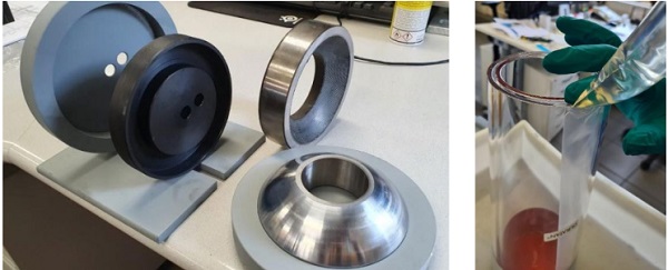
The extruded glass tubes are produced by SCHOTT in Germany. SCHOTT cut the specimens to size, fire-polished the edges and performed a first, primary check of the proper fitting of the tubes (within each other), already in the factory. After that, the glass tubes were transported to H.B.Fuller Kӧmmerling in Germany, for lamination (i.e. bonding of the tubes). A two-c omponent, Ködistruct LG, liquid resin interlayer material was chosen; its hydro-elastic nature allows for a slow curing. After it was poured, the interlayer material was heated to 40 °C to ensure that curing was complete. The tubes are laminated in a vertical position. The end-connections, steel and POM components are designed and developed with the aid of Octatube.
The steel shoes are made from CNC-milled steel rods in order to create the designed chambers. In these chambers, the POM-block and the steel hinges (Techniparts) are placed. The POM-blocks are milled from solid POM-rods to obtain the desired grooves. During assembly, strain gauges are glued to the inner and the outer glass tubes. Lastly, the HILTI HIT-HY 270 mortar is injected into the grooves of the POM-blocks, and the laminated glass tubes are placed on top. The mortar was well-distributed into the grooves and it was possible to inject it properly, whereby the glass stayed clean. In figure 7, the steel and POM components are shown, as well as the lamination process.
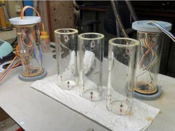
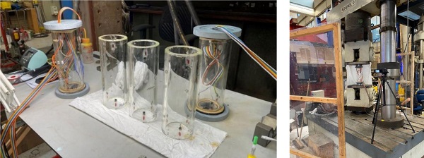
Prior to testing, the aforementioned strain gauges, glued to the glass tubes, are soldered to the connectors. Twelve strain gauges are glued to each sample, 6 on the outside and 6 and the inside. The glass is abraded lightly, at the locations where the strain gauges are glued, to make sure that the strain gauges are not falling off. After that, the wires could be soldered to the connectors as well. Timber pieces are glued inside the grooves of the POM-blocks to hold the glass at the right height. Then theHILTI HIT-HY 270 mortar could be injected, which requires approximately 5 minutes to harden. Within these 5 minutes, the mortar needed to be injected, smoothened out, and the glass needed to be placed on top of the mortar and the timber pieces at the right height. Afterwards, the wires needed to be set to zero and then the samples were ready for testing. Figure 8 shows the samples ready for testing.
4. Experimental investigation
4.1. Test set-up
A hydraulic displacement-controlled universal testing machine is used for the testing of the samples in compression with a cross-head displacement rate of 1mm/min. The samples are clamped between a head and a base plate (figure 8, right).
4.2. Differences between annealed versus heat-strengthened samples
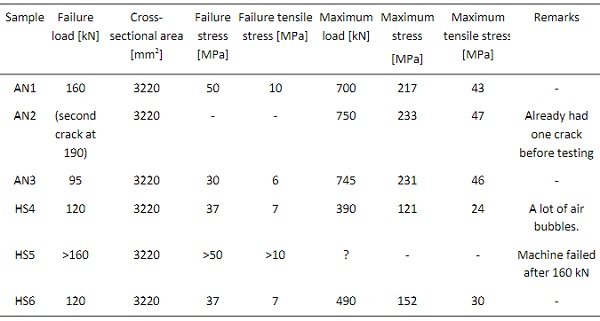
In figure 10 (left), one cracked annealed sample is shown after testing. The annealed samples (AN1-3)presented a few straight, vertical cracks parallel to the length of the tube. The cracks had a slow propagation. The first cracks appeared between 95-160 kN compression load, but complete failure only happened between 700-750 kN. Upon final release of the force, additional small perpendicular cracks appeared. Cracks appeared in both tubes, indicating a good degree of a cooperation between them.
In figure 10 (right), one cracked heat-strengthened sample is shown after testing. The heat-strengthened glass samples (HS3-4) presented considerably more cracks, again vertical and parallel to the length of the tube. The first cracks appeared at 120-160 kN. In contradiction to the annealed glass samples, cracks appeared first in the outer tube. The cracks propagated quickly with a lot of speed. When the tests are ended, due to shattering of the glass (at circa 390-490 kN), the inner tube exploded into small pieces at once. This means that the cooperation from the heat-strengthened samples is lessthan from the annealed samples. The overview of the differences between annealed versus heat-strengthened samples is given in table 1.
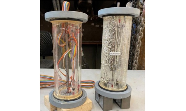
Table 1: differences between annealed versus heat-strengthened samples.
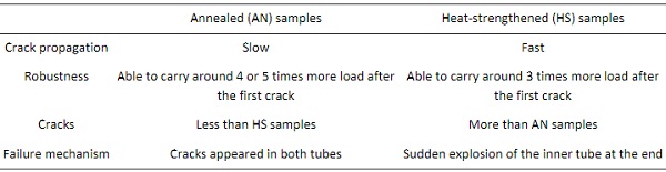
So, initial cracks appeared between a compression strength of 30-50 MPa in the DURAN® samples and between 37-50 MPa in the DURATAN® samples, which is almost at equal values. Given that heat-strengthened glass has a higher tensile strength than annealed glass, it would be expected that heat-strengthened tubes perform better and present failure at higher values compared to annealed tubes. Besides, the experiments indicated that heat-strengthened glass tubes presented less post-cracking load-bearing capacity (after initial cracking) than the annealed glass tubes.
A possible reason could be that the outer tube of the heat-strengthened samples cracked first while in the annealed specimens both tubes presented cracks. It could be that there was less of a composite action between the concentric heat-strengthened tubes and the interlayer, whereby all the stress was then taken by the outer tube only. Nevertheless, the crack pattern (degree of fragmentation) is essentially an energy release phenomenon. It is a function of the state of stress, including both the prestress and the stresses induced from loading.
In annealed glass the prestress is nearly zero, meaning that fragmentation it is mostly a function of applied stresses. In heat-strengthened glass the fragmentation is affected by both the prestress and the applied stresses. This means that it could be possible to have similar initial cracking values for the annealed and heat-strengthened glass. Another explanation could be that the loads are introduced through the edges of the tubes, whereby peak stresses do not occur in the surface.
4.3. Manual calculations
Beforehand, some manual calculations are made. No cracks are taken into account in the manualcalculations, which means that the results from the calculations and the tests could vary. The following equations are used:
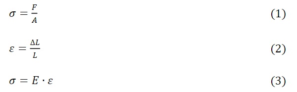
Where:
- ε: strain [-]
- F: force [kN]
- A: cross-sectional areas [mm2]
- E: Young’s modulus [MPa]
- L: length [mm]
- ΔL: displacement or difference in length [mm]
- σ: stress [MPa]
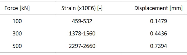
In table 2 the strains and displacements are given calculated by using equations 1, 2, and 3.
Table 2: The calculated strains and displacements.
4.4. Results
The values obtained from the manual calculations (table 2), can be compared to the average strains and displacements from the tests, given in table 3. Almost all strains and displacements from the tests are in range with the calculated values, only strain gauge 12 was deviating in sample 3, whereby the average values are lower than calculated.
The results from the tests are summed up in table 4. In here the initial failure load (when the first crack appeared) and the maximum load (when the glass samples started to shatter) with the corresponding stresses is shown. The cross-sectional area of the two glass tubes is approximately 3220 mm2. When the sample was compressed with a force of 750 kN, the compressive stresses are around 233 MPa. This is close to the theoretical maximum compression strength for borosilicate glass of 260-350 MPa (Oikonomopoulou 2019).
Tensile stresses occur due to the lateral strains caused by the Poisson’s ratio. Since the compression strength is higher than the tensile strength, the tensile strength will be reached before the compressive strength (Haldimann et al. 2008). Due to the Poisson’s ratio effects, transversal elongation will occur resulting in tensile stresses. The tensile strength in table 3 is calculated from equation 4. According to SCHOTT, the Poisson’s ratio for borosilicate glass is 0.2 (SCHOTT n.d.).
![]()
Where υ is the Poisson’s ratio.
Table 3: The average strain vales and corresponding displacements from the tests– samples 1, 2, 3, 4, 6.
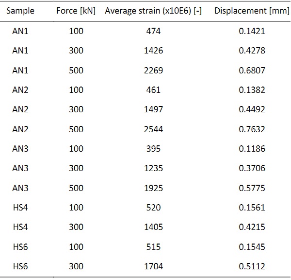
Table 4: Test results for failure and maximum load with corresponding stresses – all samples
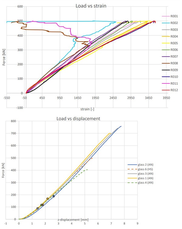
The even force distribution is checked by the strain gauges. If the forces are equal in the glass tubes, then the strains are equal. Figure 9 (left) shows a typical strain versus load curve from one of the samples. R001-R012 are the twelve strain gauges. R001-R006 are the strain gauges placed on the outside of the glass tubes, and R007-R012 are the strain gauges on the inside of the glass tubes. As shown in figure 9, in the beginning the strains are almost equal. After that, the stress field changes, whereby some strain gauges are deviating. There are a few possible reasons regarding the latter:
- Strains could deviate after cracks appeared.
- The strains may not have been positioned exactually vertically.
- The connection may not have been exactly perpendicular to the glass tubes, resulting to one side receiving more forces. Then an uneven stress distribution can occur, which results in peak stresses.
- The hinges GX50T performed as good hinged connections. However, the diameter of the hinges are large compared to the dimensions of the sample, and perhaps this affected the functioning of the hinges.
- In the tests, a few timber pieces are placed in the POM-block to keep the glass in its place. These timber pieces could also have contributed to an uneven introduction of forces into the glass.
The connections and the HILTI HIT-HY 270 mortar remained intact. Only the glass fractured. The test was ended when the glass column experienced a combination of multiple fractures and a significant drop in the load versus displacement curve. This can therefore be considered the ultimate compression capacity of the glass columns. Figure 9 (right), shows the load versus displacement curves for all the samples, except sample 5. The curve of sample 5 is not reliable, because the machine failed to record some of the data during testing.
The bullets in the graph represent the load at which the first crack appeared in the samples (the failure load). The cracks appeared between 95-160 kN. This corresponds to a compression stress of 29.5-49.5 MPa, with corresponding tensile stresses of 5.9-9.9 MPa. Based on equation 6 and 7 of NEN 2608 (2014), the allowable tensile stress for annealed glass is 15.5 MPaand for heat-strengthened glass is 36.3 MPa; which would in turn imply that in theory, the first cracks should occur at around 250 kN of compressive load with a corresponding nominal compression strength of 78 MPa with the given set-up.
Possible reasons that can explain the early cracking of glass are:
- Load fluctuations during testing or variability of material properties can contribute to lowering the probability of a flawless behaviour.
- In the calculations a perfectly hinged connection is taken into account. Compared to the dimensions of the samples, the diameter of the hinges used is large, which could have affected the functioning of the hinge as a hinged connection.
- Inherent defects at the edge of the glass tubes, manufacturing imperfections and induced imperfections at the connection surface may result in peak-stresses that compromise the overall load-bearing capacity.
- Air bubbles, located in the adhesively-bonded interlayer may also had a negative effect: stresses are localised around such air bubbles in the samples. The glass tubes of sample 4, which had the most bubbles, started shattering earlier than the other samples.
In all specimens, the cracks started from either the top or the bottom edge of the glass tubes. These cracks could be caused by transversal elongation, which resulted in tensile stresses. After cracks appeared, local stresses are relieved. The cracked glass tubes are kept together by the interlayer material, maintaining in this way a post-breakage load-bearing capacity. The curve from the load versus displacement curves continued, which means that no stiffness is lost after fracture.
5. Conclusion and future work
This study explored the potential and limitations in designing and engineering a robust, redundant, fire-proof, transparent, tubular glass column. Two variants are designed and engineered: the MLA and the SLW. Manufacturing tolerances of the glass tubes and their lamination can be challenging. The tubes need to be bonded together by lamination to become robust, and the column is replaceable when broken. Another aspect that needs attention is assembling the column. With air and water regulation, isochoric pressures and thermal stresses can be avoided. Otherwise, silica grains can be used to take up water when condensation occurs. The design of the end connections is particularly critical for the behaviour of the columns. The connections are hinged and HILTI HIT-HY 270 mortar is used to distribute the forces into the glass. Furthermore, POM-blocks are designed between the glass and the steel components.
For testing, six samples of 300 mm long and with an outer diameter of 115 mm are made of two load-bearing borosilicate glass tubes made by SCHOTT. The tubes are bonded together by H.B.Fuller Kӧmmerling. The connections are made of: a POM-block and a steel bracket (Octatube), steel hinges GX50T (technipartz) and HILTI HIT-HY 270 mortar.
Initial cracks appeared between a compression strength of 30-50 MPa in the DURAN® samples and between 37-50 MPa in the DURATAN® samples; in all cases the cracks initiated from the top or bottom edge of the glass tubes. Only the glass fractured and the connections remained intact. The stress at initial cracking is lower than predicted by manual calculations; the first cracks occurred at 34-64% of the calculated load. This can be attributed to several factors, including peak stresses occurring due to manufacturing tolerances or eccentric loading.
Still, there is a good degree of composite actionbetween the tubes due to the interlayer material. Even after fracture, samples remained stiff and strong. The nominal compression strength capacity for DURATAN® samples is around 150 MPa and for DURAN® samples around 233 MPa. The annealed samples had a slow crack propagation and are able to carry around 4-5 times more load after initial cracking. The heat-strengthened samples had a fast propagation and are able to carry 3 times more load after initial cracking.
Nevertheless, further testing is necessary in order to establish design values, because the current testing is rather limited. In order to be able to evaluate the effect of buckling in such tubular glass columns, it is necessary to perform compression tests in longer specimens. It is also advised to testsamples under impact, fire, short-term, and long-term loading. Besides, to further improve the transparency, and to reduce the shrinkage within the interlayer material, more research needs to be done on the lamination process of a tube within a tube. During tests, strain gauges are used which are glued to the glass. The values of the strain gauges are deviating, so perhaps other, more reliable, methods are possible to use to check if the strains are equal in the glass.
Furthermore, in this project samples using solely annealed or solely heat-strengthened glass tubes are tested. Perhaps a combination of annealed and heat-strengthened tubes will prove to be more efficient. The experiments indicated that heat-strengthened glass tubes presented less post-cracking load-bearing capacity (after initial cracking) than the annealed glass tubes. This can be taken into account during the design stage; different distribution of the loads can be integrated in the design of the end connections by the use of hard and soft rubber.
Acknowledgements
The authors would like to thank Fred Schilperoort and Louis den Breejen for operating the hydraulic machine during the experiments. The authors are gratefulto SCHOTT, H.B.Fuller Kӧmmerling, Octatube, Hilti, and Techniparts for their material sponsorship. We would like to particularly thankKlaas Roelfsma, dr. Folker Steden, Kerstin Kohl and Katrin Djuric from SCHOTT, Chris Davis, dr. Wolfgang Wittwer, dr. Christian Scherer and Jens Wolthaus from H.B.Fuller Kӧmmerling, Peter van de Rotten and Willem Poot from Octatube, Thomas Goedegebuure from Hilti, Frank Muntz from Techniparts. Furthermore, the authors also express their gratitude to dr. Fred Veer and Telesilla Bristogianni for their valuable feedback.
References
Achenbach, J., Jung, H.: Konstruktive Element aus Glasrohrprofilen in Tragstrukturen - Systementwicklung, Herstellung and Anwendung. GlasKon 2003, pp. 29–34. Messe Munchen GmbH, Munich (2003)
Glass & Swinging Structures bv. Dutch Design Week: Ziptruss Light structure (2021). URL: Ziptruss - Glass & Swinging Structures bv | Dutch Design Week (ddw.nl)
Eekhout, M.: Tubular Structures in Architecture. Proceedings of the 17th International Symposium on Tubular Structures (ISTS17). Research Publishing, Singapore (2019)
Doenitz, F., Jung, H., Behling, S., Achenbach, J.: Laminated glass tubes as structural elements in building industry. Glass Processing Days, pp. pp. 275-278. Tampere (2003)
Gravit, M., Klimin, N., Dmitriev, I., Karimova, A., Fedotova, E.: Fire technical properties of intumescent and ablative fire resistant glass. IOP Conference Series: Materials Science and Engineer 666 012095 (2019).https://doi.org/10.1088/1757-899X/666/1/012095
Haldimann, M., Luible, A., Overend, M.: Structural Engineering Document 10: Structural Use of Glass. Zürich, Switzerland: International Association for Bridge and Structural Engineering (2008)
Honfi, D., Overend, M.: Glass structures – learning from experts. COST Action TU0905, Mid-term Conference on Structural Glass (2013). https://doi.org/ 10.1201/b14563-72
Kalamar, R., Bedon, C., Eliášová, M.: Experimental investigation for the structural performance assessment of square hollow glass columns. Eng. Struct. 113(4), 1-15 (2016). https://doi.org/10.1016/j.engstruct.2016.01.028
NEN 2608: Glass in building - Requirements and determination method. Nederlands Normalisatie-instituut, Delft (2014)
Nijsse, R.: Glass in Structures: Elements, Concepts, Designs. Birkhauser, Germany (2003)
Nijsse, R., Ten Brincke, E.H.J.: Glass columns. In: Louter, C., Bos, F., Belis, J., Lebet, J. (eds.) Challenging Glass 4 & COST Action TU0905 Final Conference, Lausanne 2014, pp. 625–632. Taylor & Francis Group, London (2014)
Oikonomopoulou, F., van den Broek, E.A.M., Bristogianni, T., Veer, F.A., & Nijsse, R.: Design and experimental testing of thebundled glass column. Glass Struct Eng 2, 183–200 (2017). https://doi.org/10.1007/s40940-017-0041-x
Oikonomopoulou, F.: Unveiling the third dimension of glass: Solid cast glass components and assemblies for structural applications. (Doctor). Delft University of Technology, Delft (2019)
Overend, M., Vassallo, C., Camillieri, K.: The design, assembly & performance of glass columns. 9th International Conference on Automotive and Architectural Glass (Glass Processing Days), Tampere, Finland (2005)
SCHOTT. DURAN® (n.d.). URL: Technical properties of DURAN® glass tubing | SCHOTT
Van Nieuwenhuijzen, E.J., Bos, F.P., Veer, F.A.: The Laminated Glass Column. Glass Processing Days, Tampere (2005)
Veer, F., Pastunink, J.R.: Developing a Transparent Tubular Laminated Column. Glass Processing Days, pp. 277–280. Tampere (1999)