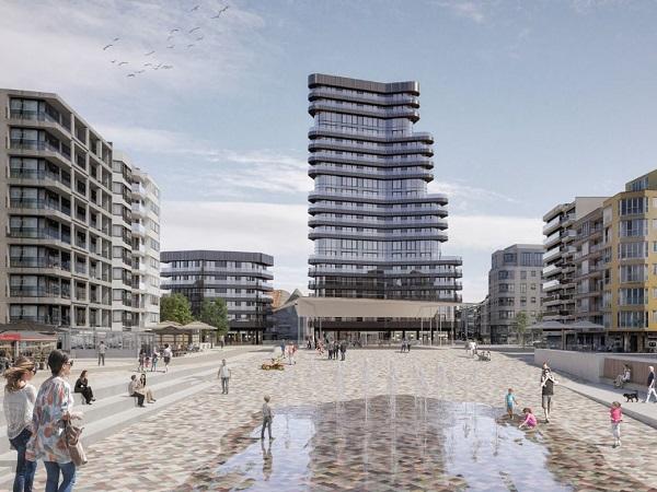
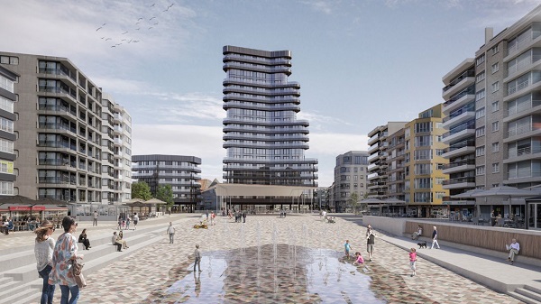
with the 67 m high residential Heldentoren (Eng. Hero tower) in the back (© Neutelings & Riedijk)")
Article Information
- Digital Object Identifier (DOI): 10.47982/cgc.8.459
- This article is part of the Challenging Glass Conference Proceedings, Volume 8, 2022, Belis, Bos & Louter (Eds.)
- Published by Challenging Glass, on behalf of the author(s), at Stichting OpenAccess Platforms
- This article is licensed under a Creative Commons Attribution 4.0 International License (CC BY 4.0)
- Copyright © 2022 with the author(s)
Authors:
- Bert Van Lancker - Vitroplena
- Kenny Martens - Vitroplena
1. Introduction
Designed by Neutelings & Riedijk and Bureau Bouwtechniek, in cooperation with project developers SALT and dvlp and built by contractor Eiffage, the Heldentoren (Eng. Hero Tower) is a 67 m high residential tower situated in the municipality of Knokke Heist at the Belgian coast. It is part of the refurbishment of the Heldenplein (Eng. Hero square) and its surroundings, including a new underground car park, new and safer traffic flows, etc. The 20 floors contain apartments with commercial areas at ground level. Figure 1 depicts a 3D visualisation of the reconstructed area of the Heldenplein with the Heldentoren as well.
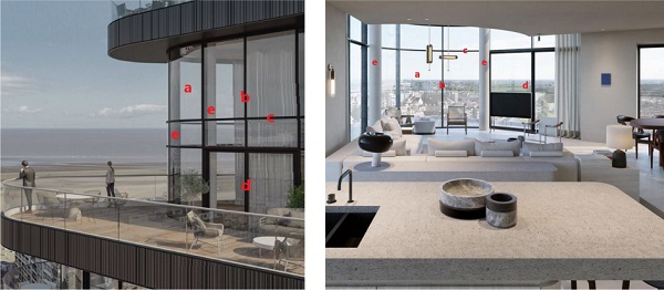
On level +2, +7, +12 and +17, the residences have curved curtain walls that span two floors instead of the curtain walls on other floors that are only spanning one floor. These duplex façades as depicted in figure 2 are 5.4 m high and consist of closed part which is straight and has length of 2.6 m, a curved part with a bending radius of 2.3 m and a total length of 4.92 m (= 3 x 1.64 m), and again a straight part with sliding doors which has a length of 2.6 m. The total height of 5.4 m is divided in a façade section of 2.3 m high, a middle section of 0.8 m high and an upper façade section of 2.3 m high. As depicted in figure 2, two columns are present near the transition of the straight part to the curved part of the façades.
These are either constructed in steel or in reinforced concrete and have a diameter of 30 cm. The glass composition of the insulating glass units proposed by the glass manufacturer is 88.2(ANG, PVB)/15(Ar)/88.2(ANG, PVB), i.e. two laminates, each consisting of two 8 mm thick monolithic annealed float glass panes separated by two PVB interlayers of 0.38 mm thick (= 0.76 mm total interlayer thickness), with an argon filled cavity of 15 mm. For the curved insulated glass units, hot bent annealed float glass is used. The profiles of the curtain walls are made from aluminium EN-AW 6060 T66 with a yield strength of 160 MPa and an ultimate tensile strength of 215 MPa according to EN 1999-1-1 :2002 (CEN, 2002).
2. Design challenges
The main challenge in the design of the duplex façade was the high aesthetical performance that the façade had to meet. The aluminium curtain wall had to be designed with minimalistic profiles to reduce the visual impact on the view to the outside and to minimise the occupied space on the inside. Standard slim profiles from the catalogue of the supplier, i.e. not custom-made and easily available, were proposed by the façade builder and approved by the building owner to use in this project. However, the structural calculations still had to confirm the possibility to use these profiles.
Secondly, the fact that the duplex façade is curved, results in the introduction of horizontal in-plane reaction forces on the anchors of the façade that connect the curtain wall with the primary load-bearing structure. Moreover, curved transoms loaded by the self-weight of the insulated glass units will be subjected to torsion and horizontal displacement components. Furthermore, the distance in between the concrete structural work and the aluminium façade is greater than for traditional curtain walls, resulting in large eccentricities or lever arms, hence large bending moments on the anchors and anchorages. This was something to take into account in the design of the anchors on the steel or concrete columns, as they are visible and therefore have to be minimalistic as possible.
A 67 m high residential tower at the Belgian coast results, for Belgium, in high wind loads. For a basic wind velocity of 26 m/s and a terrain category 0 according to EN 1991-1-4 +A1:2010 (CEN, 2010), this building is subjected to a wind peak velocity pressure of 1782 Pa. Traditional curtain wall design principles consider a simply supported beam with a span equal to the total height of the façade to model the structural response of the mullion. Similarly, the transoms are modelled as simply supported beams with a span equal to the span between two mullions.
The structural response of the mullions and transoms subjected to wind loads and the structural response of the transoms subject to the self-weight of the glass can easily be calculated based on available analytical formulas to calculate stresses and deformations in beams. Limiting the stresses to the yield stress of the applied aluminium and limiting the deflections to maximum allowable deformations according to EN 13830 (CEN, 2015) result in a minimum required resisting moment and minimum required second moment of inertia of the aluminium profiles. This approach implies a structural calculation of the curtain wall members individually, i.e. on component or element level, hence without taking into account the structural response of the system.
For this project, this would mean that the proposed slim profiles, and by extension every single profile from the supplier’s catalogue, could not be used in this project. Therefore, structural calculations on system (façade) level had to be performed. Such calculations take into account the semi-rigidity of the connections between the mullions and transoms. Doing so, a more realistic model of the duplex façade can be obtained. Moreover, the connections between mullions and transoms can be designed as such to obtain a certain level of semi-rigidity necessary to enable the application of the proposed slim profiles.
3. Structural design
3.1. Hot bent glazing
The glazing for the duplex façade as proposed by the glass manufacturer has an 88.2(ANG, PVB)/15(Ar)/88.2(ANG, PVB) composition. In the curved part of the curtain wall, hot bent glass is used. Therefore, a mould is created which has an inside surface that represents the final shape of the exterior face of the glass. The glass is heated up to 600°C and becomes rubbery. Due to gravity, the glass sags into the desired shaped defined by the mould. Afterwards, the glass is cooled down slowly to anneal it resulting in similar strength and optical qualities of annealed flat glass.
Considering a wind peak velocity pressure of 1782 Pa and initially an external wind pressure coefficient of -1.4 and an internal wind pressure coefficient of +0.2, the total wind load on the exterior 88.2 glass laminate equals -1.46 kPa in ULS (fundamental combination with γq = 1.1 and cprob = 0.96) and -1.33 kPa in SLS (characteristic combination with cprob = 0.96) taking into account the load sharing effect in insulated glass units. Application of the Effective Thickness Method as described in EN 16612:2019 (CEN, 2019) with an ω-value of 0.3 (wind gust load in other areas, stiffness family 1) results in an equivalent thickness of 14.15 mm of the 88.2 laminate for calculations in ULS and 12.86 mm for calculations in the SLS.
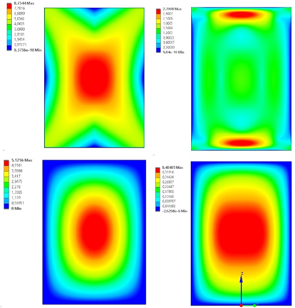
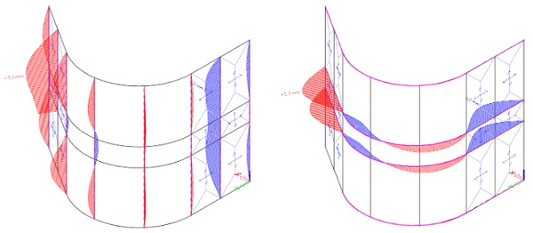
The maximum allowable principal tensile stress in the annealed glass panels equals 25.0 MPa according to NBN S23-002-2:2020 (NBN, 2020), whilst the maximum out-of-plane deflection equals 10.6 mm according to the same Belgian standard. Figure 3 depicts the maximumprincipal stresses and deformations in the external hot bent 88.2 laminate and for a flat 88.2 laminate with the same dimensions for geometrically nonlinear calculations on finite element models. Remark that even for a flat glass panel design approach glass thicknesses can be reduced to 66.2(ANG, PVB) instead of the proposed 88.2(ANG, PVB).
Structural design calculations will result in an 88.2(ANG, PVB) composition when the shear interaction is not (properly) implemented in the calculations and/or when only geometrically linear calculations are performed. Production-technically, i.e. related to the process of hot bending glass, it might be necessary to use thicker glass panels, albeit not from a structural point of view. Structurally, impact conform EN 12600:2003 (CEN, 2003) might result in thicker glass panels.
Figure 3 clearly demonstrates the beneficial effects of bent glass in comparison to flat glass. In this situation, the stresses are reduced by a factor of 3.2 and the deformation by a factor of 12.7. Remark that for the curved glass panel, maximum stresses occur near the top and bottom edge of the glazing. Hence, from a structural point of view, glass thicknesses can be reduced when taking into account the curved shape of the glass panels.
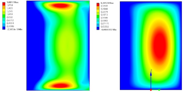
Important in this is that as a consequence of taking into account the geometrical curved shape of the glazing, the wind pressure coefficients should be adapted as well (cfr. EN 1991-1-4+A1:2010). Figure 4 illustrates the principal tensile stresses and out-of-plane deformations for the external hot bent 88.2 laminate taking into account adjusted wind pressure coefficients. The maximum principal tensile stress equals 1.9 MPa, whilst the maximum deformation equals 0.3 mm.
3.2. Aluminium curtain wall
A finite element model of the entire duplex façade, as illustrated in figure 5, was created to enable geometrically non-linear analyses taking into account semi-rigidity of the connections between mullions and transoms. Remark the following features in this model:
- the interaction between insulating glass units and aluminium framework is not modelled. Wind loads acting on the glazing are transferred to the mullions and transoms using the trapezoidal distributionprinciple, which is commonly used in curtain wall design;
- weight anchors are typically positioned at the bottom of the mullions, except at the sliding doors, where the weight anchor is positioned at the top. This implies that under self-weight all mullions are loaded in compression, except the mullion at the sliding doors that will be loaded in tension;
- anchors are also installed at a height of 2.3 m and 3.1 m (level of the transoms), both at the sides of the façade and at the primary load-bearing columns. The introduction of the anchors at the columns results in the partition of the entire façade in two ‘normal’ façades and one bent façade acting as an arch. The trust forces of this bent façade are the horizontal in-plane reaction forces which need to be transferred to the columns. The side anchors are only loaded by horizontal out-of-plane reaction forces.
- as the anchors at the columns remain visible after complete installation of the façade, they have to be designed as minimalistic as possible. These anchors, furthermore, can connect the curtain wall to either a steel column or a concrete column. The anchors and anchorages for the latter are more complex as concrete failure needs to be considered in the design as well.
- the aluminium profiles for the mullions and transoms are depicted in figure 6 a). These are part of the so-called slim line of profiles of the supplier. The width of the middle section is only 15 mm with a cavity of 11 mm wide. The part of the profile making the rabbets for the glazing is 50 mm wide;
- the semi-rigidity of the connections between the mullions and transoms is modelled as a rotational spring with a constant spring stiffness. The nodal stiffener, as depicted in figure 6 b), that introduces semi-rigidity in these connections were numerically modelled and used to determine the horizontal out-of-plane rotational stiffness and the vertical in-plane rotational stiffness which were then implemented in the finite element model of the duplex façade;
- to avoid torsion of the curved transoms and generally vertical in-plane loading of the transoms due to the self-weight of the glazing, glass bearers are used to directly transfer these loads to the mullions. As such the transoms are only loaded horizontally out-of-plane by the wind. The glass bearers, as depicted in figure 6 c), are made from stainless steel and are bolted to the mullions. The structural performance of these components was verified using finite element analyses;
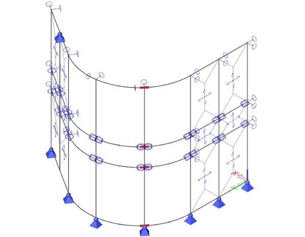
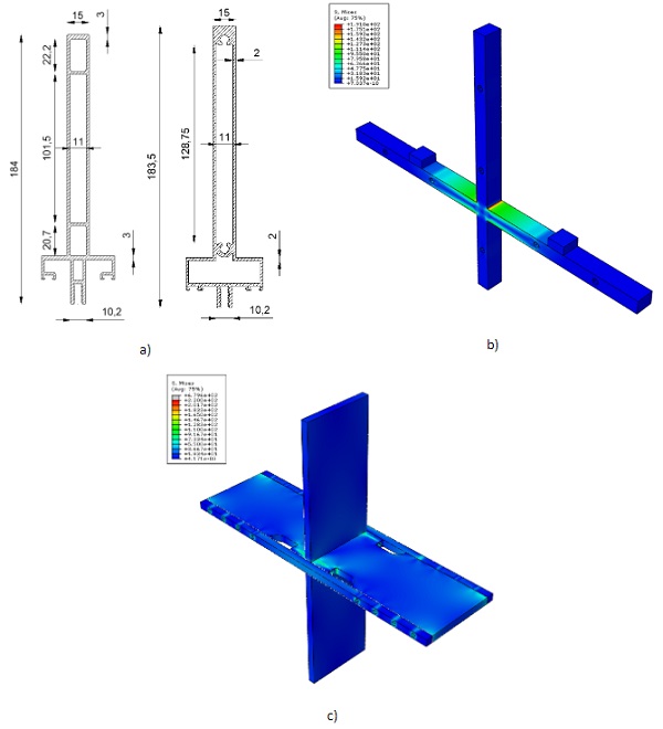
Figure 7 represents the out-of-plane bending moments in the mullions and the transoms. The effect of the semi-rigidity of the connections between mullions and transoms is clearly present as bending moments are transferred across the nodes. The maximum absolute value of the bending moments in the mullions equals 2.49 kNm instead of 10.50 kNm (= factor 4.2) for a component level calculation without semi-rigidity of the connections. In the transoms, the maximum absolute value of the out-of-plane bending moment is equal to 3.35 kNm, whilst for simplified component level calculations this parameter has a value of 6.22 kNm (factor 1.9). Hence, the node stiffeners in combination with the façade or system level calculations result in a reduction of the moment of resistance of the mullions with a factor of 4.2 and with a factor of 1.9 for the transoms.
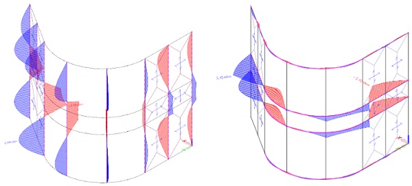
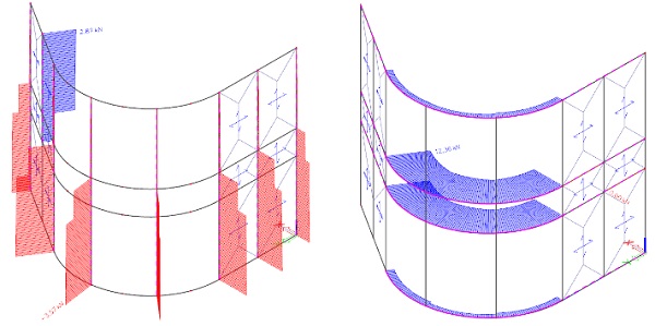
Figure 8 depicts the normal forces in the mullions and transoms of the duplex façade. The mullion above the sliding doors is subjected to tensile loads, whilst all other mullions are loaded in compression. For the latter, the resisting normal force will be determined taking into account buckling phenomena. For the first, vertical displacements have to be limited to avoid blockage of the sliding doors. Therefore, steel inserts are provided to increase the stiffness and to reduce therefore the local deformations. The normal forces in the transoms clearly demonstrate the arch effect of the curved façade resulting in horizontal in-plane reaction forces on the anchors and anchorages at the columns.
Figure 9 illustrates the out-of-plane deformations of the mullions and transoms of the duplex façade. The maximum out-of-plane displacement equals 7.0 mm when considering node stiffeners and system level calculations. This is smaller than the allowable value of 5 + L/300 = 5 + 3100/300 = 15.3 mm. For simplified component level calculations without the presence of node stiffeners, the maximum deflection would be 96.2 mm for a maximum allowable value of 5 + L/300 = 5 + 5400/300 = 23.0 mm. This demonstrates that for component level calculations without node stiffeners, the second moment of inertia of the mullions would have to be 4.2 times higher than which is now the case. The out-of-plane deflection of the transoms equals 5.9 mm for an allowable value of L/200 = 2640/200 = 13.2 mm. Again for the simplified calculation, the deflection would be 93.9 mm, which would require a second moment of inertia which is 7.1 times higher than for the proposed transom profile.
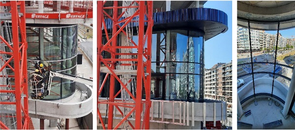
4. Mock-up
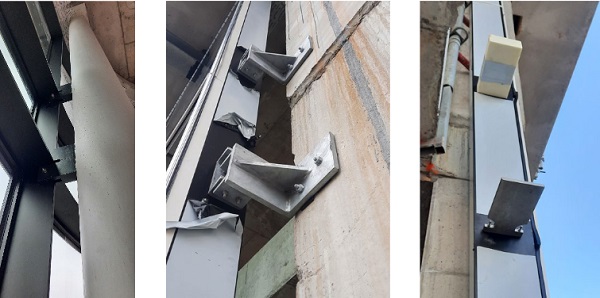
Figure 10 demonstrates the mock-up of the duplex façade on the second level of the Heldentoren during construction. Figure 11 depicts some details, such as the visible anchors at the steel columns which were designed as minimalistic as possible, the anchors at the sides of the façade near the structural work and the node stiffeners between the transoms and the mullions. Remark the large distance between curtain wall and primary load-bearing structure resulting in large eccentricities which results in solid and robust anchors and anchorages.
The use of this mock-up allows the building owner and architects to give feedback with respect to aesthetical aspects of the duplex façade. Whilst for the façade builder, technical issues and installation-related difficulties can be identified and solved. Potential consequences of these interventions with respect to the structural performance of the façade can be revised as well.
5. Conclusions
The structural design of the duplex façade of the 67 m high residential tower Heldentoren was presented in this paper. The 5.4 m high aluminium curtain wall contained a curved section with a bending radius of 2.3 m, split up in three parts of 1.64 m wide. 88.2(ANG, PVB)/15(Ar)/88.2(ANG, PVB) was the applied glass composition and for the curved part hot bent glass was used.
It was demonstrated that by taking into account shear interaction of the interlayers by modelling viscoelastic material behaviour, by implementing the curved shape of the glazing in the geometrical model and by performing geometrically nonlinear finite element analyses result in glass compositions which are more economical than proposed by the glass manufacturer.
The main challenges with respect to the structural design of the façade were the required aesthetical performance with minimalistic profiles, the curvature of the façade resulting in horizontal in-plane reaction forces on the anchors and anchorages and the impossibility to apply traditional curtain wall design principles as these led to oversized cross-sections of the profiles. To solve these issues, stainless steel glass bearers and node stiffeners were used in combination with structural calculations on system or façade level, i.e. taking into account the stiffness of the connections between mullions and transoms in the geometrically nonlinear finite element analyses.
As such, a minimalistic design that satisfies the requirements regarding stiffness (serviceability limit state) and strength (ultimate limit state) was obtained. Out-of-plane bending moments in the mullions and transoms could be reduced by a factor of 4.2 and 1.9 respectively compared to traditional curtain wall design calculations. Out-of-plane deflections of the mullions were also a factor 4.2 higher for simplified calculations, whilst for the transoms even a factor of 7.1 had to be taken into consideration.
The anchors faced the problem of large eccentricities, acting horizontal in-plane reaction forces, anchorages in concrete columns with a diameter of 30 cm and visibility after completion resulting in the need of a minimalistic design. A mock-up was built to enable the identification and solution of technical issues and installation-related difficulties. Potential consequences of these interventions with respect to the structural performance of the façade could be revised as well.
Acknowledgements
Vitroplena would like to acknowledge Hermans & Co for the opportunity to collaborate on this project. Marc Velleman of Hermans & Co in particular is thanked for the pleasant cooperation and for the permission to use his photographic material.
Architects Neutelings & Riedijk and Bureau Bouwtechniek, project developers SALT and dvlp, and contractor Eiffage are acknowledged as well for their permission to publish the contents of this paper.
References
EN 12600:2003 Glass in building – Pendulum test – Impact test method and classification for flat glass. European Committee for Standardization, CEN (2003).
EN 13830:2015 Curtain walling – Product standard. European Committee for Standardization, CEN (2015).
EN 16612:2019 Glass in building – Determination of the lateral load resistance of glass panes by calculation. European Committee for Standardization, CEN (2019).
EN 1991-1-4+A1:2010 Eurocode 1 – Actions on structures – Part 1-4: General actions – Wind actions (Consolidated version, including AC:2010 and A1:2010). European Committee for Standardization, CEN (2010).
EN 1999-1-1: 2002 Eurocode 1 – Actions on structures – Part 1-1: General actions – Densities, self-weight, imposed loads for buildings. European Committee for Standardization, CEN (2002).
NBN S23-002-2:2020 Glaswerk – Deel2: Berekening van de glasdikte. Bureau voor Normalisatie, NBN (2020).