Architectural Glass Laminating Guide - Part 8
By Luc Moeyersons
One could catalogue the PhotoVoltaic lamination process also under “non-autoclave lamination process”. But because of the size of the industry (and of the popular request), I decided to treat it as a separate item.
I will not dwell on the different PV technologies but remain in the domain of lamination.
Principle functioning of PV laminator:
Stage 0: Loading of the laminate.
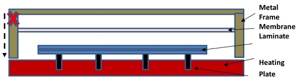
The laminate is introduced into the vacuum chamber (pins down).
Advised laminate temperature: 20 – 25 °C.
Once the laminate is in place, pins are rising.
But due to the limited contact from the laminate to the heating plate, a small increase in
temperature (one interface of the laminate) can be noticed.
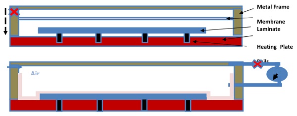
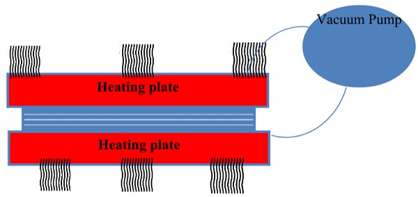
Stage 1: De-airing (= evacuation).
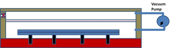
Consequently, the air is also removed from between the PVB/glass of the laminate sandwich.
Due to the close contact of the heating plate (despite the vacuum) the laminate is warming up.
Once the required maximum laminate temperature has been obtained for the demanded time, the laminate is cooled of (under vacuum).
Examples of live systems:
- a. Single chamber laminator (3S – Meier-Burger)
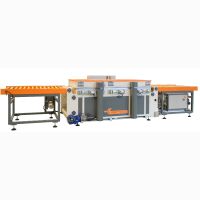
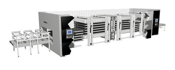
- b. Multi stack laminator (Buerkle Ypsator)
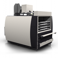
- c. Most recent development (TekniSolar Robostak)
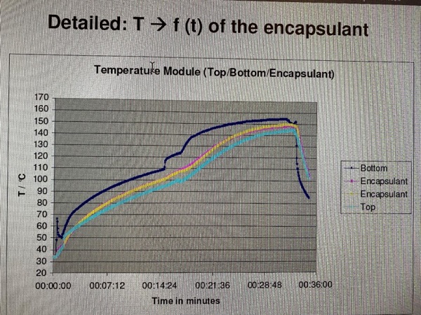
a. 3S laminator – bottom side heated. Heating plate: 155 C
Laminate: 3.2 mm glass/0.76 mm PVB/ 3.2 mm glass
Program setting:
- 15 minutes de-airing; pins up.
- 2 minutes pins down
- 20 minutes membrane pressure (500 mbar)
- Pressure release and cooling for 20 minutes (remove laminate to cool separately)
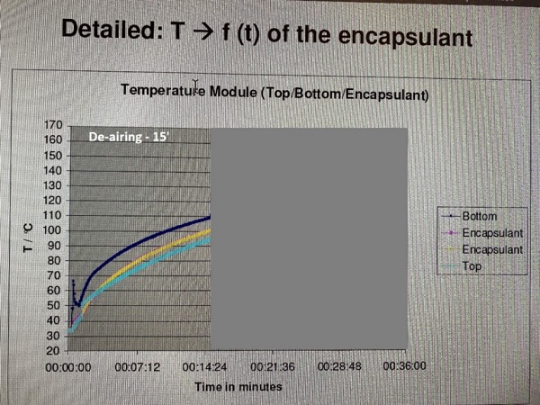
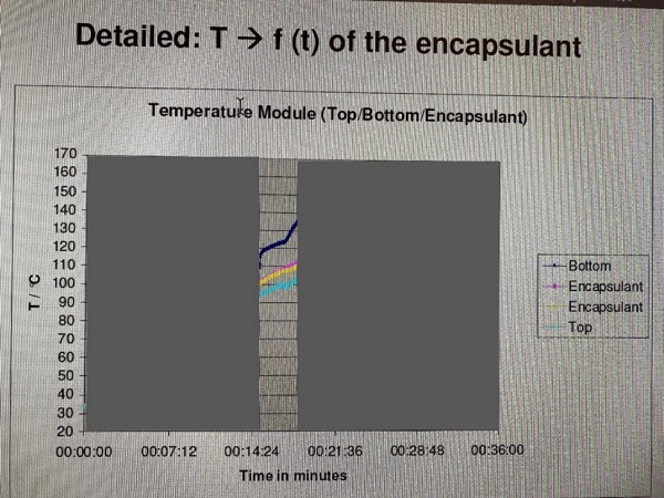
Stage 1 : de-airing
Due to heat and weight of glass, PVB starts to flatten the roughness and reducing/closing de-airing channels.
PINS UP: No contact to the heating plate.
Temperature of laminate increases due to heat radiation of heating plate (no convection since under vacuum).
De-airing (down to 1 mbar)
The temperature of the interlayer/encapsulant ramps up to app. 80 C (in 15 minutes)
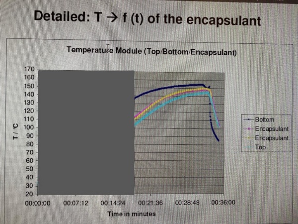
Stage 2: Heating
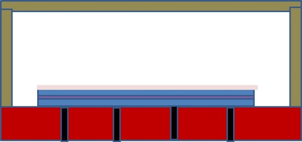
Stage 2 a: Heating (through heat conductivity)
The pins are lowered (usually by membrane pressure) and the laminate/module makes contact to the heating plate.
There is heat transfer via conductivity
Stage 2 b: Heating (heat conductivity helped by contact/pressure)
Membrane pressure is applied (500 mbar)
The membrane pressure ensures an intimate contact between the laminate and the heating plate. The PVB starts to flow at higher temperatures.
The PVB temperature ramps further up to 145° C. (in 20 minutes). Minimum temperature needed to achieve full adhesion: 125° C. Ensure uniform temperature!
NOTE: for laminators without pins, one can use an insulation tissue (e.g.: felt) (to limit excess warming of laminate sandwich and interlayer/encapsulant.
e.g.: Airtech Airweave NC10 (app. 3 mm thick)
Bleeder Lease E (app. 0.1 mm thick)
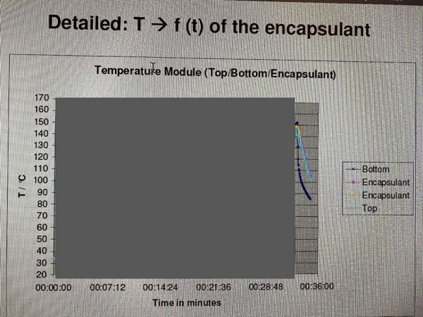
Stage 3: Vacuum release and cooling:
The vacuum chamber is vented (vacuum and membrane pressure relief).
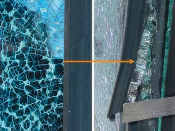
Cool down the laminate/module to prevent blow-ins (cooling step outside of the laminator)
Cool till around 50° C to stop interlayer/encapsulant flow (to prevent blow-ins)
Total process cycle.
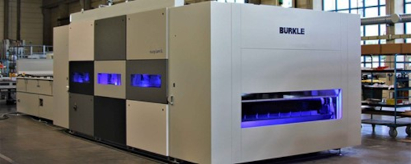
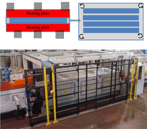
b. Buerkle laminator:
A more sophisticated, multi stack laminator.
Laminate: 2.1 mm glass/0.76 mm PVB/ 2.1 mm glass
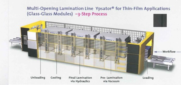
Differences versus other laminators:
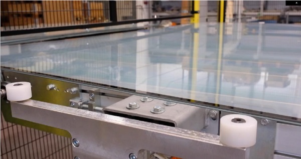
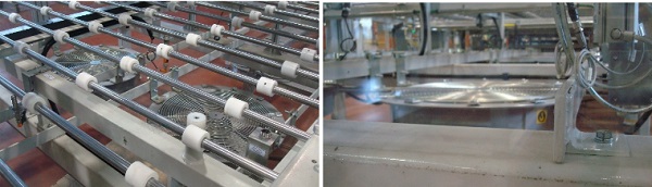
Chamber 1: no pins, but rails/conveyor belts
Chamber 2: 2 side heating
Can exceed 1000 mbar pressure.
Chamber 3: 2 side cooling (under pressure)
Process flow:
1. Evacuation:
The module/laminate is held off the heating plate by rails. (no contact to heating plate)
When the evacuation is finished, the membrane presses the module/laminate down onto the heating plate (sealing the laminate edges to prevent air to enter the laminate sandwich again.)
The laminate/module enters the next chamber.
2. Heating/Pressing:
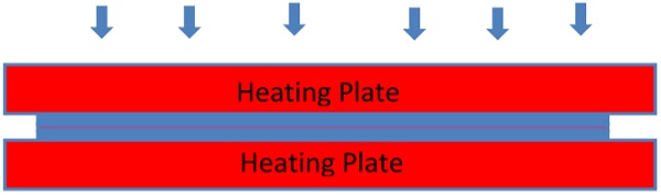
The laminate/module is in between 2 hot plates.
These are closing in parallel position. Uniform heat through symmetric design/lay-up.
A thin cushion layer between module/laminate and heating plate prevents glass breakage.
The laminate/module enters the next chamber.
3. Cooling:
The laminate/module is in between 2 cooling plates.
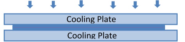
A thin cushion layer between module/laminate and heating plate prevents glass breakage.
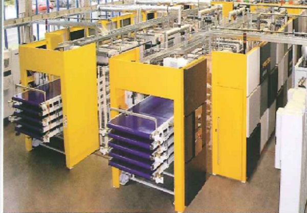
Multi-stack Laminator (Ypsator):

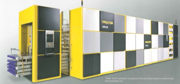
Laminating 5 stacks + 3 steps = 15 laminates/modules at the same time.
Set up = 2 machines next to one another = 30 laminates/modules.
12 minutes to make 10 laminates/modules.(2 times 5)
50 modules/hour or 400 modules/shift = 1200 modules/day in 3 shift operation.
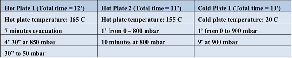
c. Teknisolar Robostak
When the center of gravity of Photovoltaic module production moved from Europe to Asia, most laminator producing companies ceased investigating/introducing further process improvements. One of the exceptions was TekniSolar, run by ex-Engineering Manager from Pilkington: Vittore de Leonibus. Being a “late starter”, helped the company to understand the pros/cons of various existing systems of PV lamination.
The concept that came out of that market survey, was the following:
- Fast de-airing to avoid use of pins.
- Avoid membrane (one of the weak/expensive components of PV laminators), potentially creating edge pinching.
- Uniform heating (not only from one side)
- Integrate cross linking time in the concept without adding processing time.
After some iterations, the following laminating concept line was produced.
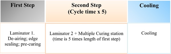
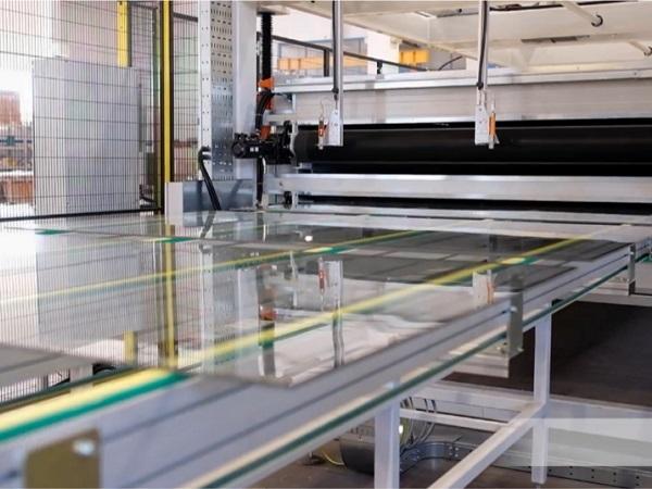
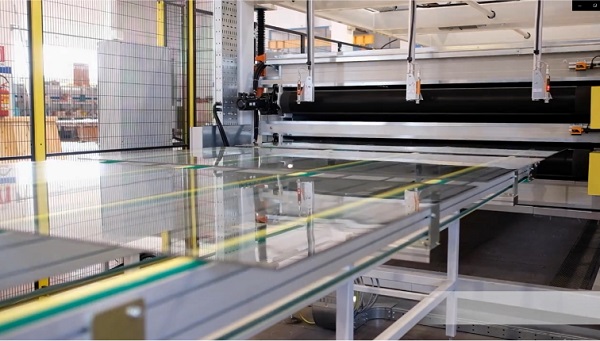
First Step: Laminator 1:
The PV module enters the laminator, through a conveyor, already being in contact to the bottom hot plate.
The laminator closes and the chamber is put under vacuum using a combined system of vacuum pumps ensuring 2 mbar vacuum in 25 seconds. The vacuum chamber heats from top and bottom (avoiding warping of the glasses).
This concept is patented by Teknisolar.
The membrane is replaced by a rigid heating plate, without pins since the thorough vacuum system allows full deairing prior to edge sealing by the warming interlayer/encapsulant.
De-airing and heating of the module sandwich happens within the same time frame.
Second step: Laminator 2 (pressing and curing):
This step consists of 2 chambers. (Laminator 2 and curing section)
Laminator 2, identical to laminator 1.
In the laminator heating is achieved from top and bottom.
When ready, the module is introduced into the curing oven. This curing oven can be designed according to customers’ needs (vertical or horizontal), here the modules stay 4 times the time frame of the press cycle.
There are 5 modules in the laminator 2 and the curing oven, so that each module can stay in polymerisation modus for 5 times the actual cycle time.
Third step: Cooling:
The modules are cooled by fans, supplying a controlled volume of air (controlled by invertors).
Once cooled to the right temperature, the modules are deposited on the exit conveyor.
Output Robostak
Typical Cycle Time for EVA/POE lamination
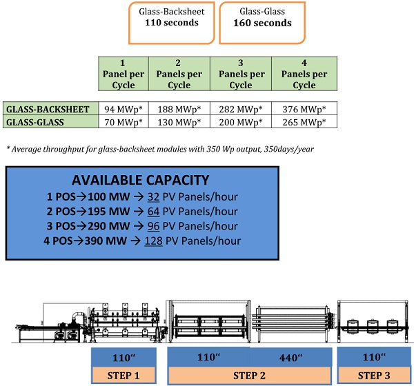
When the cycle time of the laminator is 110 seconds, one needs to realise that each module is in the lamination process for a total of 770 seconds, or app. 13 minutes.:
- 110 seconds for de-airing and edge sealing (step 1)
- 550 seconds for crosslinking (step 2)
- 110 seconds for controlled cooling (step 3)
PRODUCTIVITY WITH ONE LAMINATOR WITH 3 POSITIONS
![]()
Other PV laminator producers:
- Wemhoener; Planckstraße 7, 32052 Herford, Germany;
https://www.wemhoener.de/en/information/product-information
- Buerkle; Stuttgarter Str. 123, 72250 Freudenstadt, Germany
https://www.burkle.tech/int-en/applications/laminators/solar-modules
- Spire Solar USA Massachusetts
https://www.directindustry.com/prod/spire-solar/product-63104-521676.html
- NPC (– Meier) Japan
- SM InnoTech GmbH & Co KG; Vennweg 18, 46395 Bocholt, Germany
https://www.sm-innotech.de/en/products/laminators/laminator-incapcell/
- BudaSolar; Konkoly Thege Miklos ut 29-33 Budapest, 1121 Hungary
- Teknisolar – Via Marisa Bellisario, 26, 66050 San Salvo – Italy
https://teknisolar.com/
- Ecoprogetti – Via dell'Industria e dell'Artigianato 27/C, 22/D – Carmignano di Brenta 35010 - Padua - Italy
https://ecoprogetti.com/products/laminators/
- Mondragon
- Qinhuangdao - Boostsolar Photovoltaic Equipment Co., Ltd.
https://boost-solar.com/
- Hanwha Corporation; South Korea
- Shaanxi Beiren Printing Machinery Co., Ltd; China
- Ooitech; China
- REOO; China
See also https://www.enfsolar.com/directory/equipment
Pictures are shown with reference to the source of the picture.
If the info is wrong, please contact author with correct info for document correction.
This information corresponds to our current knowledge on this subject. It is offered solely to provide possible suggestions for your own experiments. It is not intended, however, to substitute for any testing you may need to conduct to determine for yourself the suitability of our advice for your particular purposes.
This information may be subject to revision as new knowledge and experience become available. Since we cannot anticipate all variations in actual end-use conditions, LAMI Solutions makes no warranties and assumes no liability in connection with any use of this information.
Nothing in this publication is to be considered as a license to operate under or a recommendation to infringe any patent right.