First presented at GPD 2019
The study consists of three laboratory test series, all executed at room temperature. In the first series, pull-out tests are performed on thin metal inserts laminated between two glass plies. These pull-out tests show a considerable pull-out resistance and consistency in test results. In the second series, shear tests are performed on thick metal buttons laminated to monolithic glass pieces.
These shear tests show again a considerable shear strength of the metal-toglass connection and small scatter in the test results. In the third series, tension tests are performed on similar button specimens as used for the shear tests.
These tension tests show high consistency in tension stiffness, but a relatively large dispersion in ultimate failure load. Overall, it is concluded that the structural PVB offers a considerable metal-to-glass bond strength which calls for further investigation of its potential in structural glass connections.
1. Introduction
Laminated metal-to-glass connections are a modern connection type used in structural glass engineering. Such laminated connections make use of solid foil adhesive interlayers to create a connection between glass and metal connector parts. Laminated connections are typically produced in an autoclave lamination cycle commonly used for the production of laminated glass units. As such, laminated connections differ from “conventional” adhesive connections which are typically produced by means of liquid adhesives that are subsequently cured.
Distinction can be made between two main types of laminated connections [Santarsiero and Louter, 2013] [Bedon & Santarsiero, 2018]. The first type, here called embedded laminated metal-to-glass connections, consist of either thin metal sheets or thick metal parts which are integrated in a laminated glass unit, as done by e.g. [O`Callaghan, 2007; Belis et al. 2009; Carvalho and Cruz, 2012; Puller and Sobek, 2012; Santarsiero et al. 2016a: Torres et al. 2017]. The second type, here called externally laminated metal-to-glass connections, consist of metal parts which are laminated either to the outer glass surface or to the edge of a (laminated) glass unit, as done by e.g. [Peters et al. 2007; Belis et al. 2009; Sitte et al. 2011; Santarsiero et al., 2016b; Santarsiero et al 2017; Drass et al. 2018; Ioannidou Kati, 2018a].
The current paper investigates both types of laminated metal-to-glass connections and provides an exploratory study into the use of a structural polyvinyl butyral (PVB) foil interlayer, Saflex Structural DG41 XC [Eastman Chemical Company, 2019], for the creation of such laminated metal-to-glass connections.
Through pull-out tests on embedded laminated metal-to-glass connections (pullout specimens) and tension and shear tests on externally laminated metal-to-glass connections (button specimens), the metal-toglass bond strength of this structural PVB is investigated.
2. Specimens
For this study, two different types of metalto-glass laminated specimens have been produced, as described in the following subsections. All specimens have been laminated at the facilities of Eastman Chemical Company.
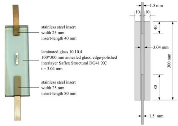
2.1 Pull-out specimens
The pull-out specimens (Figure 1) consist of:
- Laminated annealed glass 10.10.4; 100*300 mm; edge polished prior to lamination.
- Saflex Structural DG41 XC interlayer; nominal thickness t = 3.04 (4 layers of 0.76 mm).
- Stainless steel (AISI 304) inserts; t = 1.5 mm; width 25 mm; insert length 40 and 80 mm.
In these specimens, the structural PVB interlayer is used both for glass-to-glass and metal-to-glass bonding. Initial bonding was established through vacuum-bag lamination, followed by a standard autoclave lamination cycle to complete the lamination process. It should be noted that no steel to glass contact is present in these specimens (Figure 1b).
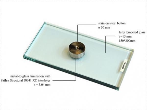
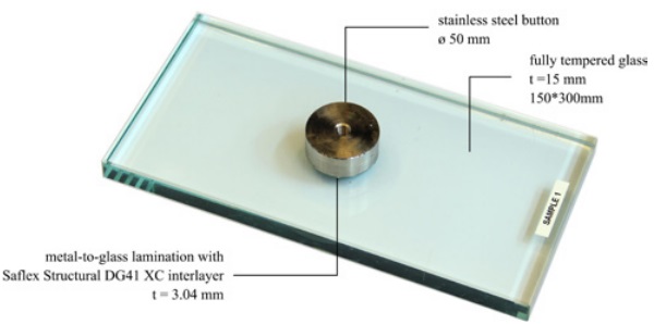
2.2 Button specimens
The button specimens (Figure 2) consist of:
- Monolithic fully tempered glass; t = 15 mm; 150*300mm.
- Stainless steel (AISI 316) button; diameter 50 mm; thickness 15 mm.
- Saflex Structural DG41 XC interlayer; nominal thickness t = 1.52 mm (2 layers of 0.76 mm).
In these specimens, the structural PVB interlayer is used for metal-to-glass bonding. Initial bonding was established through vacuum-bag lamination, followed by a standard autoclave lamination cycle to complete the lamination process. Teflon and steel accessories were used to prevent excessive flow of the interlayer during the lamination process.
3. Methods
Three different test setups are used within this study, as described in the following sections. All tests are executed at TU Delft.
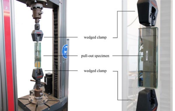
3.1 Pull-out test method
For the pull-out tests a Zwick 100 kN universal test machine with wedged clamps is used (Figure 3). The specimens are placed vertically and the exterior parts of the metal inserts are clamped in the wedged brackets. The clamps are manually tightened to prevent slipping of the metal inserts in the bracket.
By moving the upper clamp upwards at a fixed displacement rate of 1 mm/minute a tension force is applied on the specimens, thereby pulling the inserts out of the laminate. During the tests, the force and machine displacement are recorded. The tests are executed at room temperature (23°C ±3°C) without temperature conditioning.
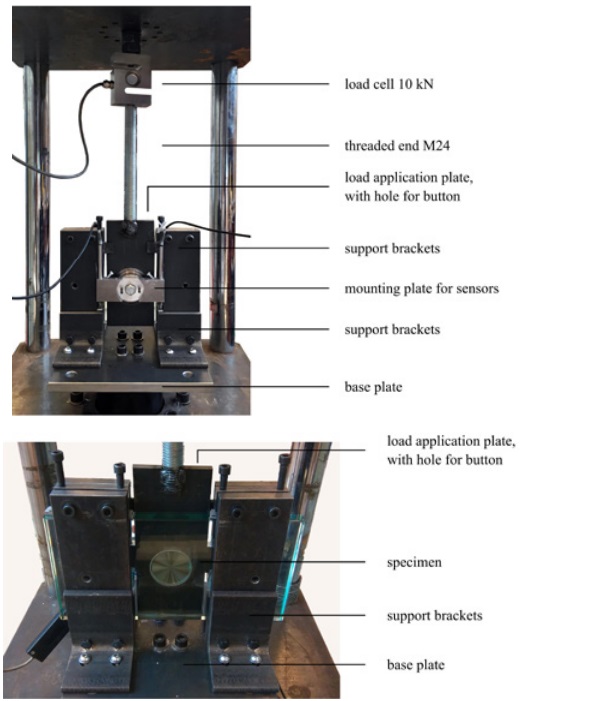
3.2 Button shear test method
For the button shear tests, a SCHENK testing machine provided with a 10 kN load cell is used (Figure 4). The specimens are placed vertically and supported laterally by support brackets mounted on a base plate. A 10 mm thick steel plate with a circular hole is positioned over the button of the specimen and connected to the load cell by means of an M24 threaded end.
By moving the base plate downwards at a displacement rate of 1 mm/minute, a shear load is applied on the button of the specimen. On the button a mounting plate is placed with two displacement sensors that measure the relative shear displacement of the button with respect to the glass. During the tests, the force, the machine displacement and the displacement measured by the sensors are recorded.
The tests are executed at room temperature (23°C ±3°C) without temperature conditioning. The design of the test setup is based on earlier studies done by [Santarsiero et al. 2016b] and is identical to the one used in the study of [Ioannidou Kati et al. 2018b].
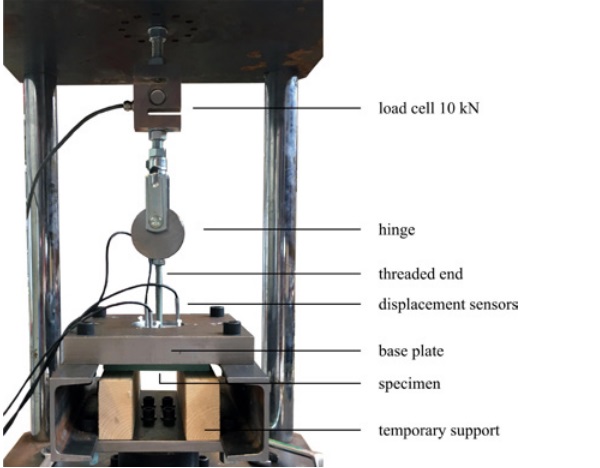
3.3 Button tension test method
For the button tension tests, a SCHENK testing machine provided with a 10 kN load cell is used (Figure 5). The specimens are mounted horizontally underneath a steel base plate, which is provided with a circular hole, in which the button of the specimen is positioned. The button is connected to a hinge by means of a threaded end, which itself is connected to the load cell.
By moving the base plate downwards at a fixed displacement rate of 1 mm/minute, a tension force is applied on the button of the specimen. The relative displacement of the button with respect to the glass is measured by means of displacement sensors mounted on the button.
During the tests, the force, machine displacement and the displacement measured by the sensors are recorded. The tests are executed at room temperature (23°C ±3°C) without temperature conditioning. The design of the test setup is based on earlier studies done by [Santarsiero et al., 2017] and is identical to the one used in the study of [Ioannidou Kati et al. 2018].
4. Results
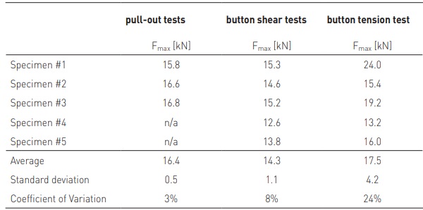
The results of the pull-out, button shear and button tension tests are collected in Table 1. The force-displacement diagrams and observations during the tests are presented in the following subsections.
4.1 Results pull-out tests
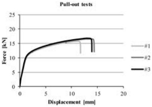
The force-displacement diagrams of the pull-out tests are presented in Figure 6. The specimens show a high consistency in initial pull-out stiffness. At a load of about 10 kN the pull-out stiffness starts to decrease.
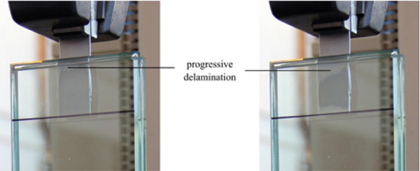
During the experiment, it was observed that the metal insert elongates during the test and that progressive delamination occurs from the free glass edge inwards (Figure 7).
It is assumed that the combination of metal elongation, delamination and interlayer deformation causes the reduction in pull-out stiffness. Full delamination of the upper (40 mm long) insert occurs at an average load of 16.4 kN (Table 1).
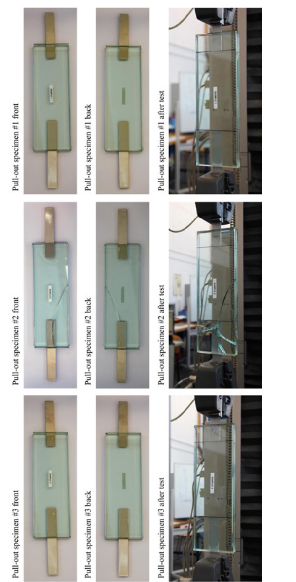
Due to the complex geometry of the pull-out specimens, some imperfections in terms of lamination quality (bubbles) were observed in the specimens (Figure 10). These do not seem to result in large variation of the pullout force. An overview of all specimen prior to and after the tests is given in Figure 10.
It should be noted that the glass of specimen #2 was already cracked prior to testing. During testing, additional cracking occurred in specimen #2, which caused a small disruption in the force-displacement diagram (Figure 6). However it can be seen that the cracks did not significantly affect the overall response of the specimens.
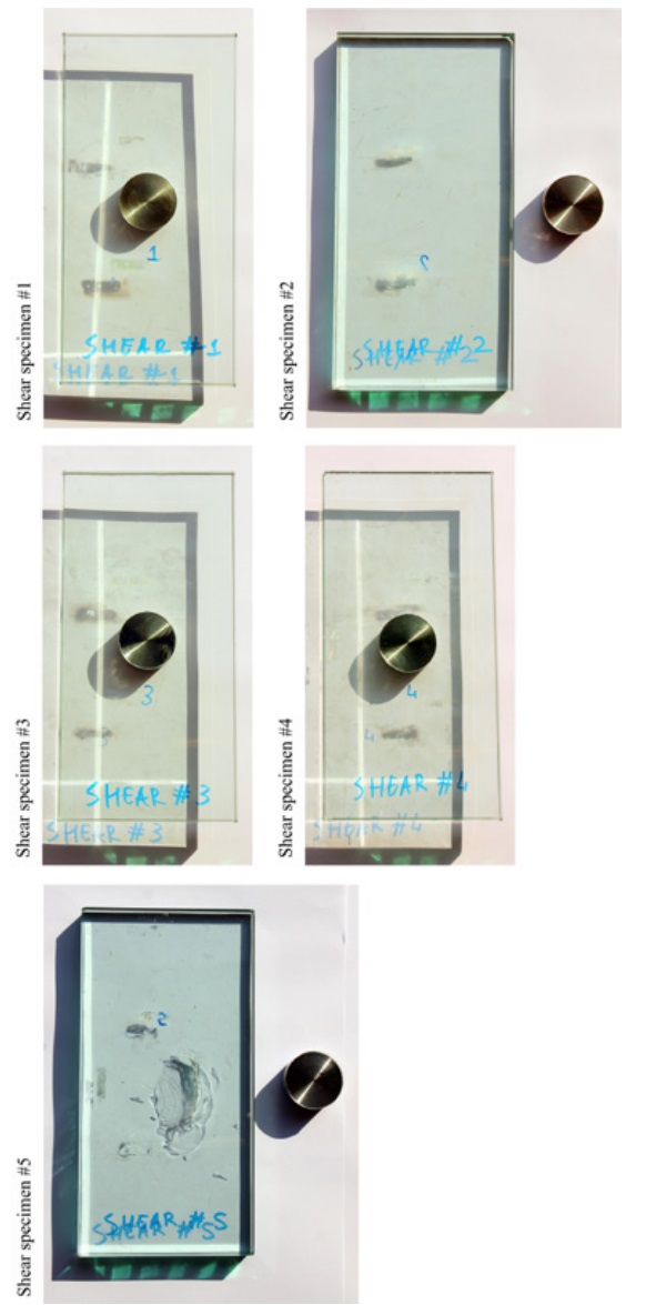
4.2 Results button shear tests
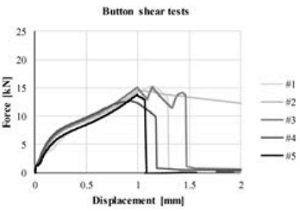
The force-displacement diagrams of the button shear tests are presented in Figure 8. The plotted displacement corresponds to the averaged value of the two displacement sensors.
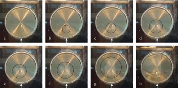
After initial settlements of the setup (until ~1.8 kN) the specimens show consistent force-displacement trajectories. During the experiment, it was observed that progressive delamination occurs in the specimens (Figure 9) which is assumed to cause the reduction in shear stiffness as seen in the force-displacement diagram (Figure 8).
Full delamination of the specimens, at the glassto-interlayer interface, occurred at an average load of 14.3 kN (Table 1). Only for specimen #5 plucking of the top glass surface occurred (Figure 11).
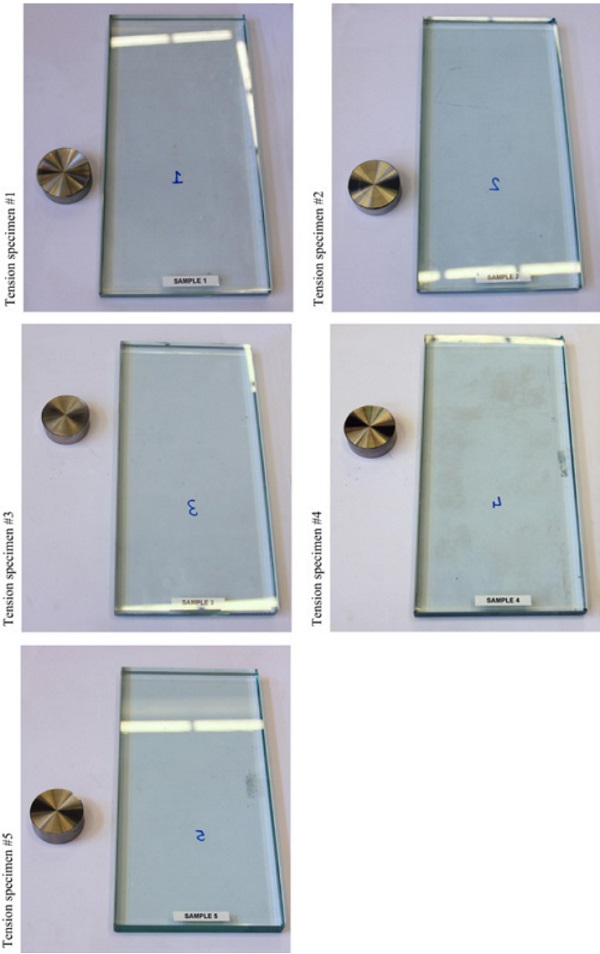
4.3 Results button tension tests
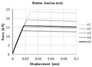
The force-displacement diagrams of the button tension tests are presented in Figure 12. The plotted displacement corresponds to the averaged value of the three displacement sensors.
The specimens show high consistency in tension stiffness (Figure 12) but a relatively large dispersion in ultimate failure load which amounts to 17.5 kN on average with a 24% coefficient of variation (Table 1).
The latter could be due to the high sensitivity of tensile specimens to eccentricity and geometrical imperfection. This high sensitivity could be linked to the high confined state of the adhesive which results in high tensile stiffness.
Failure of the specimens occurs due to sudden and full delamination of the button at the glass-to-interlayer interface, while the metalto-interlayer interface remained largely intact. An overview of all tested specimens is given in Figure 13.
5. Summary & Conclusions
In this paper, the results of an exploratory study into the metal-to-glass bond strength of a structural PVB interlayer, Saflex Structural DG41 XC [Eastman Chemical Company, 2019], are presented. The study includes pull-out, button shear and button tension tests which are all executed at room temperature.
The pull-out tests show an ultimate failure load of 16.4 kN on average. The results show limited scatter, with a coefficient of variation of 3%. This indicates the specimens were produced with relatively high consistency and that the observed small imperfections (bubbles) at some of the laminated metal-to-glass surfaces did not significantly affect the pull-out resistance.
The button shear tests show an ultimate failure load of 14.3 kN on average, with a coefficient of variation of 8%. Failure occurred predominantly due to delamination at the glass-to-interlayer interface, while the metal-to-interlayer interface remained intact. For one specimen plucking of the glass surface occurred.
The button tension tests show an ultimate failure load of 17.5 kN on average, with a high coefficient of variation of 24%. This high coefficient of variation may (at least partially) be caused by small inclinations of the metal button as resulting from the lamination process. This may have caused uneven tensioning of the laminated surface and thus stress intensifications and premature failure in certain regions of the bonding.
For both the button shear and button tension tests, failure of the specimens was dominated by delamination (adhesive failure) at the glass-to-interlayer interface, while the metalto-interlayer interface remained largely intact. The latter indicates a profound metal-tointerlayer adhesion strength. In this respect it should be noted that the surface roughness of the metal buttons and the glass specimens has not been determined in this exploratory study. Any difference in actual surface area bonded by the interlayer may have influenced at which interface failure occurred. Further studies will investigate this in more detail.
Overall, it can be concluded that the structural PVB, Saflex Structural DG41 XC, shows a considerable metal-to-glass bond strength for the given specimen geometries and test temperature. Further studies will focus on the effects of temperature and loading rate to take into account the visco-elastic properties of the interlayer. Moreover, the number of specimens tested in this study was limited, and thus further testing will include a larger set of specimens to allow for a profound statistical evaluation.
Acknowledgements
The support of Eastman Chemical Company and especially Dr. Wim Stevels in providing technical support and the specimens needed for this study is gratefully acknowledged. Also the support of Kees Baardolf (TU Delft) in preparing the test setups and Fred Schilperoort (TU Delft) in executing the button tensile and shear tests is acknowledged.
References
Bedon, C. & Santarsiero M. (2018). Transparency in Structural Glass Systems Via Mechanical, Adhesive, and Laminated Connections – Existing Research and Developments. Advanced Engineering Materials, published online, 10.1002/adem.201700815
Belis, J., De Visscher, K., Callewaert, D. & Van Impe, R. (2009). Laminating metal-to-glass: preliminary results of case-study. Glass Performance Days 2009, 191–193
Carvalho, P. & Cruz, P.J.S. (2012). Connecting Through Reinforcement – Experimental Analysis of A Glass Connection Using Perforated Steel Plates, in Challenging Glass 3, 2012.
Drass, M., Schwind, G., Schneider, J. & Kolling, S. (2018). Adhesive connections in glass structures— part I: experiments and analytics on thin structural silicone. Glass Struct Eng 2018, 3: 39. https://doi. org/10.1007/s40940-017-0046-5
Eastman Chemical Company (2019), Product Technical Data Saflex® Structural (DG) Polyvinyl Butyral Interlayer – accessible at https://www.saflex. com/products/saflex-structural-pvb-interlayer
Ioannidou Kati, A., Santarsiero, M. & Louter, C. (2018a). Proceedings of the Challenging Glass Conference 6 (CGC 6): International Conference on Architectural and Structural Applications of Glass. Louter, C., Bos, F., Belis, J., Veer, F. & Nijsse, R. (eds.). TU Delft Open, p. 359-368. https://doi. org/10.7480/cgc.6.2159
Ioannidou Kati, A., Santarsiero, M., de Vries, P., Teixeira De Freitas, S., Nijsse, R., & Louter, C. (2018b). Mechanical behaviour of Transparent Structural Silicone Adhesive (TSSA) steel-to-glass laminated connections under monotonic and cyclic loading. Glass Structures and Engineering, 3(2), 213-236. https://doi.org/10.1007/s40940-018-0066-9
O’Callaghan, J. (2007). An all glass cube in New York city. Glass Performance Days 2007, 98–10
Peters, S., Fuchs, A., Knippers, J. & Behling, S. (2007). Ganzglastreppe mit transparenten SGPKlebeverbindungen – Konstruktion und statische Berechnung, Stahlbau, vol. 76, no. 3, pp. 151–156, Mar. 2007.
Puller, K. & Sobek, W. (2012). Load-carrying behaviour of metal inserts embedded in laminated glass, in Challenging Glass 3, 2012.
Santarsiero M. & Louter C.(2013). Embedded and point laminated adhesive connections for glass structures : parametric non-linear numerical investigations, in Glass Performance Days, 2013, pp. 265–273.
Santarsiero, M., Louter, C. & Nussbaumer, A. (2016a). Laminated connections for structural glass components: a full-scale experimental study. Glass Structures and Engineering, 2 (2017), 1-23. https:// doi.org/10.1007/s40940-016-0033-2
Santarsiero, M., Louter, C. & Nussbaumer, A. (2016b). Laminated connections for structural glass applications under shear loading at different temperatures and strain rates. Construction and Building Materials, 128, 214-237. https://doi. org/10.1016/j.conbuildmat.2016.10.045
Santarsiero, M., Louter, C. & Nussbaumer, A. (2017). Laminated connections under tensile load at different temperatures and strain rates. International Journal of Adhesion and Adhesives, 79, 23-49. https://doi.org/10.1016/j.ijadhadh.2017.09.002
Sitte, S., Brasseur, M.J. Carbary, L.D. & Wolf, A.T. (2011). Preliminary Evaluation of the Mechanical Properties and Durability of Transparent Structural Silicone Adhesive (TSSA ) for Point Fixing in Glazing, J. ASTM Int., vol. 8, no. 10, pp. 1–27, 2011.
Torres, J., Guitart, N. & Teixidor, C. (2017). Glass fins with embedded titanium inserts for the façades of the new Medical School of Montpellier. Glass Structures and Engineering journal, 2017, issue 2: 201. https://doi.org/10.1007/s40940-017-0049-2