Article Information
- Digital Object Identifier (DOI): 10.47982/cgc.10.712
- Published by Challenging Glass, on behalf of the author(s), at Stichting OpenAccess.
- Published as part of the peer-reviewed Challenging Glass Conference Proceedings, Volume 10, June 2026, 10.47982/cgc.10
- Editors: Christian Louter, Freek Bos & Jan Belis
- This work is licensed under a Creative Commons Attribution 4.0 International (CC BY 4.0) license.
- Copyright © 2026 with the author(s)
Authors: Xiaohan Hao a , Suwen Chen a b
a College of civil engineering, Tongji University, China
b State Key Laboratory for Disaster Reduction in Civil Engineering, Tongji University, China

Abstract
Anticlastic cold bent glass plate plays a significant role in the design of free-form glass facades. Residual stresses will be introduced in the plate during the cold forming process which may influence the subsequent load bearing capacity. Current research on load-bearing performance of anticlastic cold bent glass plates primarily focuses on the influence of support conditions, cold bending degree, and load patterns. However, effective support conditions for post-cold-bent loading have not yet been determined, and effective failure criteria have yet to be established. In this paper, a series of load bearing tests have been conducted to explore the mechanical properties and failure mechanisms of anticlastic cold bent glass plates. Then, the effective finite element models have been built to systematically investigate the effects of support conditions, cold bending extent, width-thickness ratio and aspect ratio.
1. Introduction
The free form glass facades require double curved glass elements, for which anticlastic glass is an important plate type yet difficult to produce. Traditional hot bending approach realizes desired shape piece by piece using prefabricated mould and high temperature heating. Comparatively cold bending approach is more economic and adaptive for producing anticlastic glass plates. During this process, forces are applied at the corners of the glass plate while the other corners are fixed in out-of-plane direction. (Eekhout 2010; Neugebauer 2014; Bijster 2016; Beer 2013)
Existing research mainly focuses on the cold bending behaviour of glass plates, including the identification of instability phenomena, the prediction of instability occurrence and the analysis of influencing factors. Staaks and van (van 2004) discovered that the instability controlls the failure of cold bending. Dimension of the glass panel (Benjamin 2015; Mainil 2015; Datsiou 2016; Spagnoli 2019; Bensend 2016), the support condition (Benjamin 2015; Datsiou 2016; Bensend 2016), gravity (Benjamin 2015; Datsiou 2016; Bensend 2016; Datsiou 2017) and initial defect (Benjamin 2015) are main factors affecting the cold bending stability. Some tests have proved that laminated glass, especially laminated thin glass, has better cold forming capacity (Mainil 2015; Caprili 2017; Galuppi 2014). However, research on the subsequent load-bearing performance remains scarce, which is the primary focus of this paper.
Anticlastic cold bending introduces stress and initial shape into the glass plate, which may affects the subsequent load-bearing performance(Timoshenko and Woinowsky-Krieger 1959). Current research on the load-bearing performance of anticlastic cold-bent glass plates have focused on the stiffness evolution and failure modes under uniformly distributed/concentrated loads (Caprili et al. 2017; Quaglini et al. 2020; Galuppi et al. 2018; Bensend 2018; Nehring and Siebert 2018). Quaglini (2020) applied vertical uniformly distributed loads to point-supported monolithic glass plates before and after cold-bending instability, defining failure modes as instability or distortion exceeding optical performance requirements. The results indicated that cold-formed glass beyond its cold-bending instability point exhibits enhanced resistance to wind loads. Nehring and Siebert (2018) analyzed the mechanical behavior of thin anticlastic cold bent glass plates, with two edge supports, subjected to a concentrated load at its center.
The cold bent glass plate under frame support exhibits superior performance under load, making it the predominant subject in most post-cold-bent loading studies (Hoffmeister et al. 2017; Caprili et al. 2017; Galuppi et al. 2018). Bensend (2018) investigated the effects of membrane stress and cold-bending degree on stiffness in framed monolithic glass. Finite element analysis revealed that larger membrane stress leading to more pronounced reductions in load-bearing stiffness. Galuppi (2018) performed finite element analysis on frame-supported laminated glass subjected to uniformly distributed loading after cold bending. Results indicated maximum stresses occurred at the mid-edge of the plate, with stress values far exceeding those of flat plates under identical loading conditions. A simplified finite element model was proposed, substituting the cold-bending effect with equivalent glass stiffness. Hoffmeister (2017) investigated the influence of different structural adhesives, support conditions, cold bending degrees, and loads (wind pressure and suction). Caprili (2017) proposed an “S+G” steel-glass hybrid structural element which simultaneously satisfies flexibility requirements during cold-forming and rigidity demands under loading. Pölzl (2017) investigated the mechanical behavior of cold-formed insulating glass units.
In summary, research has been conducted on the load-bearing performance of anticlastic cold-bent glass plates, primarily focusing on comparative analysis under different support conditions, investigating the impact of cold bending on loaded stiffness, and attempting to establish control conditions for post-cold-bent loading through stress, optical distortion, and buckling. However, a unified standard for failure modes of cold-bent glass plates under loads remains absent. Systematic analysis of the key parameters affecting the load-bearing capacity of cold-bent plates is lacked, including varying support conditions, the cold bending degrees, width-thickness ratios and aspect ratios.
To address these issues and investigate the load-bearing performance of cold-bent glass plates under uniformly distributed loads, in this paper, loading tests were conducted and effective finite element model was established to analyze the characteristics of deflection and stress in cold-bent glass plates.
2. Uniformly distributed loading test on anticlastic cold bent glass plate
2.1. Introduction
This study conducted load tests on anticlastic cold bent glass plates, primarily investigating the effects of support conditions, cold bending degrees, aspect ratio, and width-thickness ratio on load-bearing performance.
For point support, the adhesive clamps are attached to the four corners of the glass plate. The centre of each clamp is positioned at a distance of 50 mm from the plate edge. Each clamp is designed to rotate around a ball-head bolt, and is bonded to the glass surface using silicone adhesive. The spherical hinge has been demonstrated to reduce bending moments under out-of-plane loads, rendering it suitable for anticlastic cold bent glass plates. The point supported glass plate construction is shown in Fig. 1(a)-(b), where B, L, h represents the width, length and thickness of the glass plate, respectively.
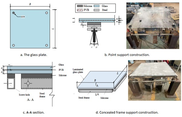
The concealed frame supported glass plate features a frame made of hollow rectangular steel tubes along four edges, which are bonded to the glass surface using silicone adhesive,as demonstrated in Fig 1(c)-(d). Preliminary finite element analysis and literature studies indicate that cold-bending deformation is concentrated at the corners. Consequently, the corner's rotational degrees of freedom are released to reduce stress concentration. Holes are drilled at both ends of the steel frame to facilitate bolting to the support via three-sided angle steel.
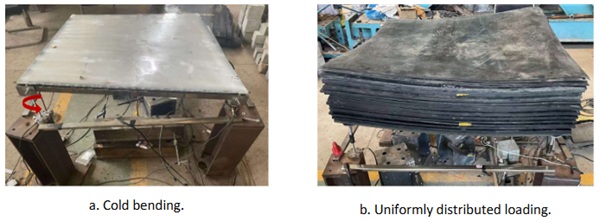
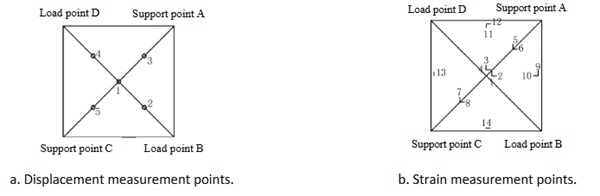
Cold bending achieves corner displacement by rotating the screw, with height controlled via a scale ruler. Once cold bending reaches the specified degree, the screw is secured, as shown in Fig. 2(a). To ensure uniform distribution of the load across the plate surface, flexible rubber pads measuring 1000 mm×1000 mm×10 mm are employed. The uniformly distributed load is applied by layering the pad on the plate surface, as shown in Fig. 2(b). Displacement measurement utilise CMOS-1L laser displacement sensors, with a measurement accuracy of ±0.05% of full scale. The measurement points are distributed along the diagonals, see Fig.3(a). The strain measurement utilise 3BA right-angle strain gauges and 3AA uniaxial strain gauges, with a total of 14 measurement points distributed, see Fig.3(b). In accordance with the loading requirements, all points have been conducted on the lower surface of the glass plate. The weighing sensor is calibrated and has a range of 20kN with an accuracy of 0.1%, measuring the reaction forces at the corner bolts. The testing process can be divided into three stages: firstly, generating initial deflection under gravity; secondly, rotating the two corner bolts diagonally to form an anticlastic surface; finally, fixing the cold-bent position and stacking rubber pads on the plate surface to simulate uniformly distributed loading until failure.
2.2. Test results and analysis
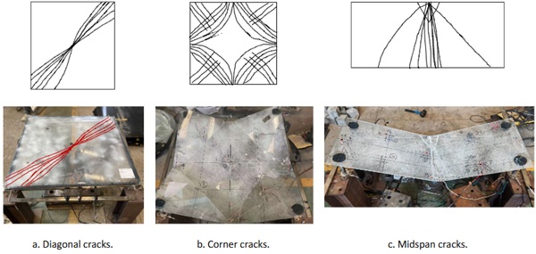
The failure modes for all specimens are glass cracking, which can be categorised into three types based on crack distribution: namely, diagonal cracks, corner cracks and midspan cracks. The distribution of these three crack types exhibits a congruence with the strain distribution across the plate surface. For all concealed frame supports, the maximum strain occurs at the plate centre, with diagonal cracks forming (see Fig.4a). For point-supported square plates, the maximum strain occurs at the midpoints of the four edges, with corner cracks forming (see Fig.4b). For rectangular plates, the maximum strain appears at the centre of the long edge, with cracks concentrated at the midspan of the long edge (see Fig. 4c).
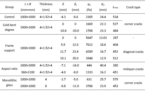
The key mechanical properties of the specimens are shown in Table 1, where 'δ' denotes the plate centre deflection induced by cold bending, 'δz ' represents the corner displacement induced by cold-bending, 'qcr ' indicates the load at cracking, 'dcr ' represents the plate centre deflection at cracking, and 'εmax ' represents the maximum strain on the plate surface at cracking.
Table 1: Summary of key mechanical properties.
3. Load Bearing Performance of Anticlastic Cold Bent Glass Plates
3.1. Finite element model and verification
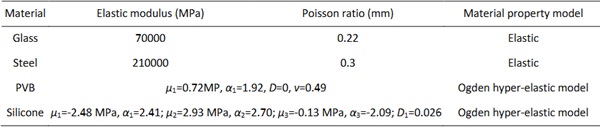
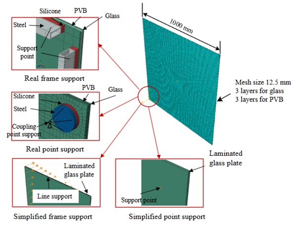
Finite element model is established using ABAQUS®. Glass and steel are simplified as elastic materials using C3D20R solid elements, while silicone and PVB employ the hyperelastic Ogden model using C3D20RH hybrid elements. Material parameters are shown in Table 2. The mesh size was set to 12.5 mm×12.5 mm, with local refinement at support area. The glass, silicone and PVB are divided into three layers along the thickness, while two layers for steel. The following three static general analysis steps are applied sequentially: gravity, cold bending load, and uniformly distributed load. Due to the flexibility of silicone sealant, only out-of-plane displacement is constrained, while allowing rotation and in-plane displacement.
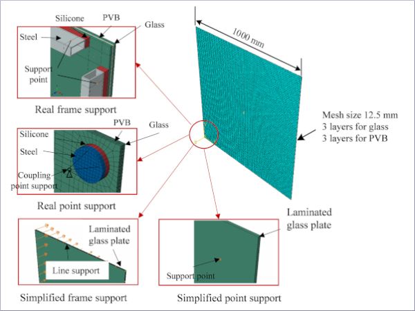
Frame-supported and point-supported models are shown in Fig.5. In the case of the frame support, 15×30×2 mm rectangular steel tubes are affixed to the glass plate using 8 mm silicone adhesive. To reduce the stiffness at the corners, 30 mm clearance is maintained at each corner. Two support points are established at each corner, with a distance of 15 mm from the edge of the rectangular steel tube. In the case of the point support, 70 mm diameter steel connector is bonded to the glass plate at a distance of 50 mm from the edge using 6 mm silicone adhesive. A coupling point is established externally to the support point in order to simulate the rotation of a universal connector, with constraints applied at the coupling point. For simplification, frame support is directly applied to the glass plate edge, and point support is applied at a distance of 50 mm from the glass plate edge. The adhesive slippage is not taken into considerations. Interfaces between PVB and glass, silicone and glass, and silicone and steel are connected by tie.
Table 2: Material models and key parameters.
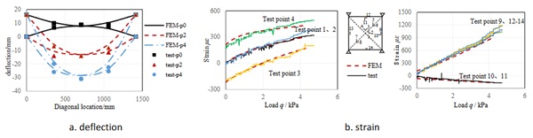
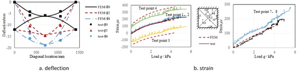
The deflection and strain of a laminated glass specimen measuring 1000 mm×1000 mm×(4+1.52+4) mm under two types of support conditions during loading are demonstrated in Fig. 6 and Fig. 7. q₀, q₂ and q₄ denote uniformly distributed loads of 0, 2 kPa and 4 kPa, respectively. The finite element strain and deflection demonstrate a satisfactory correlation with experimental outcomes throughout the entire loading process, indicating the effectiveness of the built finite element model.
3.2. Load bearing performance of anticlastic cold bent glass plates
Deformation during loading process
Under point-supported conditions, taking a 1000 mm×1000 mm×4 mm monolithic glass plate as an example, the deflections along the two diagonal directions subjected to uniformly distributed load coincide without cold bending, and the stiffness gradually increases with loading (Fig.8a). For cold-bent glass plate with corner displacement δz =20 mm, the bending directions of the two diagonals are initially symmetrical and opposite. Under uniformly distributed loading, the diagonal closer to the load (axis 1) exhibits continuously increasing deflection. while the diagonal further from the load (axis 2) gradually changes its bending direction as the load increases. The entire glass plate transitions from anticlastic to synclastic (Fig.8b).
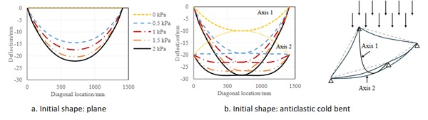
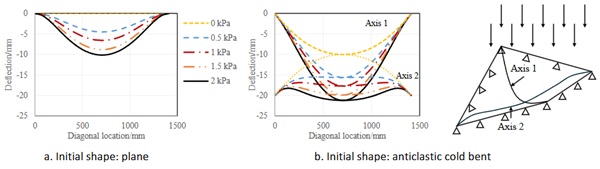
For frame-supported monolithic glass plate without cold bending, the plate subjected to uniformly distributed load exhibits consistent deformation along both diagonals, with significantly higher stiffness than point-supported glass plate (Fig.9a). Deformation is constrained near the edges, with deflection concentrated in the middle of the plate. The diagonal further from the load (axis 2) bends in the same direction as axis 1 in the middle, but in the opposite direction near the edges (Fig. 9b).
Strain during loading process
Fig.10 shows the maximum principal stresses on the plate surface in the case of point support. In (a)-(d), the glass plate has been cold-bent prior to loading; in (e)-(h), the un-cold-bent plate bears uniformly distributed loads up to 2 kPa. Regardless of whether the glass plate is cold bent, bending stresses concentrate at the midpoints of the four edges, with lower stresses at the centre of the plate. Maximum principal stress is larger in (a)-(d), because the location of the maximum principal stress from cold bending also lies at the midpoint of the plate edge, resulting in a greater combined stress.
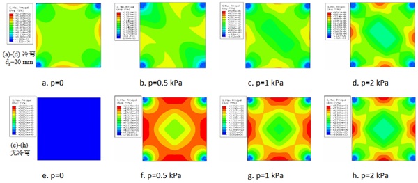
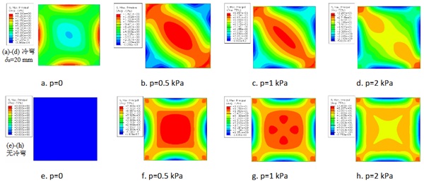
Fig.11 shows the maximum principal stresses on the plate surface in the case of frame support. Irrespective of cold bending, the maximum principal stress initially concentrates at the plate's midpoint. As the uniformly distributed load increases, stress concentration also occurs at the corners. In contrast to point-supported conditions, the stress at the plate edges is negligible. The diagonal closer to the uniformly distributed load exhibits larger tensile stress due to the influence of cold bending.
4. The Influencing factors
4.1. Support conditions
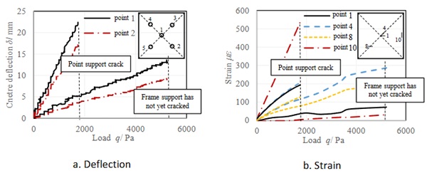
Support conditions significantly influence the load-bearing performance after cold bending. As shown in Fig. 12(a), when subjected to uniformly distributed load without cold bending, the maximum deflections for both point-supported and frame-supported plates occur at the plate's centre, while the deflections at measurement points 2–5 remain consistent throughout loading. The concealed frame exhibits greater stiffness under load due to increased edge constraints. As illustrated in Figure 12(b), for point-supported conditions, the maximum strain is observed at point 10 (mid-edge of the plate). For frame support, the maximum strain is observed at point 4 on the 45° direction within the plate. The maximum strain development for frame support progresses more slowly, with a more uniform distribution. The concealed frame exhibits greater load-bearing capacity, with no signs of cracking even under a load that exceeded the cracking load for point-supported glass by a factor of three.
4.2. Cold bending degree
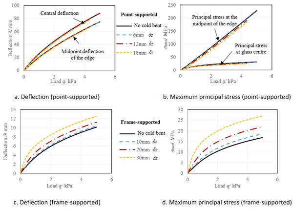
In the context of two specific support conditions, disregarding gravitational effects, cold-bending displacement is applied at two corners of a 1000 mm×1000 mm×4 mm monolithic glass plate, followed by uniform loading up to 5 kPa. In the context of point support conditions, the impact of varying cold-bending degrees on deflection and stress is found to be negligible (see Fig. 13a-b). In the context of frame support, an increase in cold-bending degrees leads to a decrease in plate stiffness and an acceleration in stress development (see Fig. 13c-d).
4.3. Width-thickness ratio
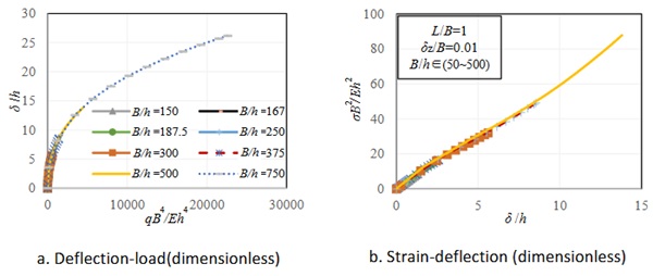
It has been demonstrated that frame-supported glass plates exhibit superior loading performance; consequently, frame support is selected as the support condition for subsequent analysis. As shown in Fig. 14, the dimensionless deflection and stress of frame-supported monolithic plate under loading exhibit consistent relationships across different width-thickness ratios. Higher width-thickness ratio leads to more pronounced nonlinearity in stress and deflection development, and the nonlinearity of mid-point deflection is even more evident, because a larger width-thickness ratio induces a relatively larger deflection, thereby enhancing the membrane effect under frame support conditions.
4.4. Aspect ratio
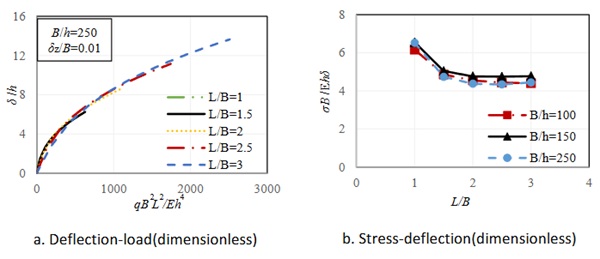
For different aspect ratios under frame-support, the key parameters are the plate centre deflection (location of the maximum deflection) and the strain at the midpoint of the plate's long side (location of the maximum strain). The results, see Fig. 15, indicate that the dimensionless load-deflection relationship exhibits a consistent trend, and the dimensionless stress-deflection relationship is influenced by aspect ratios.
5. Summary and outlook
This paper investigates the load-bearing performance of glass plates after cold bending, combining lab tests and detailed numerical simulations. The results are summarized as follows:
- Uniformly distributed loading tests on cold bent plates revealed three types of cracking patterns: diagonal cracks, corner cracks and midspan cracks.
- Cold bending degree significantly affects its load-bearing performance for framed-supported plates: the higher the cold bending degree, the faster the development of stress and deflection. Under point-supported conditions, the degree of cold bending has a minimal impact on load-induced deflection.
- Higher width-thickness ratio leads to more pronounced nonlinearity in stress and deflection development.
- For aspect ratio larger than 1, the stress is concentrated in the midpoint of the plate's long side, and the influence of other parameters are minimal.
However, this paper only considers uniformly distributed static load conditions. Future research can examine how cold-bent glass plates respond to non-uniformly distributed loads, cyclic loading, as well as their dynamic performance.
References
Eekhout M, Lockefeer W, Staaks D.: Design and Build of a Warped Tram Station, in Challenging Glass 2 – Conference on Architectural and Structural Applications of Glass. 2010. DOI: 10.7480/cgc.2.2305
Neugebauer J.: Applications for Curved Glass in Buildings. Journal of Facade Design and Engineering, 2014(2): p. 67-83. DOI: 10.7480/jfde.2014.1-2.882
Bijster J, Noteboom C, Eekhout M.: Glass Entrance Van Gogh Museum Amsterdam. Glass Structures & Engineering, 2016(1): p. 205–231. DOI:10.1007/s40940-016-0022-5
Beer B.: Complex geometry façades—introducing a new design concept for cold-bent glass, in Proceedings of GPD. 2013.
Van Herwijnen F., Staaks D., Eekhout M.: Cold Bent Glass Sheets in Façade Structures. SEI Discussion, 2004, 14(2).
Benjamin M.: Cold-Bent Glass Structures. Ecole Polytechnique Federale Delausanne-Icom, 2015.
Mainil T.: Exploratory investigation on the cold bending of thin glass. gent, 2015.
Datsiou K.C., Overend M.: The mechanical response of cold bent monolithic glass plates during the bending process. Engineering Structures, 2016, 117: p. 575-590.
Spagnoli A., et al.: Geometrically non-linear bending of plates: Implications in curved building façades. Construction and Building Materials, 2019, 214: p. 698-708.
Bensend A.: Maximizing the Twist of Cold Formed Glazing, in Challenging Glass 5-Conference on Architectural and Structural Applications of Glass. 2016.
Datsiou K.: Design and Performance of Cold Bent Glass. Cambridge, 2017.
Caprili S., Mussini N., Salvatore W.: An innovative solution for hybrid steel-glass self-bearing modular systems. Journal of Constructional Steel Research, 2017(130): p. 159-176.
Galuppi L., Massimiani S., Royer-Carfagni G.: Buckling phenomena in double curved cold-bent glass. International Journal of Non-Linear Mechanics, 2014(64): p. 70-84.
Timoshenko S, Woinowsky-Krieger S.: Theory of plates and shells. 1959.
Caprili S, Mussini N, Salvatore W.: An innovative solution for hybrid steel-glass self-bearing modular systems[J]. Journal of Constructional Steel Research, 2017, 130: 159-176. DOI: 10.1016/j.jcsr.2016.12.014
Quaglini V, Cattaneo S, Biolzi L.: Numerical assessment of laminated cantilevered glass plates with point fixings[J]. Glass Structures & Engineering, 2020, 5(2): 187-204. DOI: 10.1007/s40940-020-00119-5
Galuppi L, Di Biase P, Schaaf B, et al.: Hybrid steel-glass cell: cold-twisting and buckling phenomena[C]// Proceedings of Challenging Glass 6: Conference on Architectural and Structural Applications of Glass. Delft: IOS Press, 2018: 201-212. DOI: 10.7480/cgc.6.2149
Bensend A.: The effects of cold warping on glass stiffness[C]// Proceedings of Challenging Glass 6: Conference on Architectural and Structural Applications of Glass. Delft: IOS Press, 2018: 345-356. DOI: 10.7480/cgc.6.2119
Nehring G, Siebert G.: Design concept for cold bent shell structures made of thin glass[C]// Proceedings of Engineered Transparency 2018: Glass in Architecture and Structural Engineering. Düsseldorf: Glasstec, 2018.
Hoffmeister B, Di Biase P, Richter C, et al.: Innovative steel-glass components for high-performance building skins: testing of full-scale prototypes[J]. Glass Structures & Engineering, 2017, 2(1): 57-78. DOI: 10.1007/s40940-016-0034-1
Pölzl F.: Mechanical behavior of cold-bent insulating glass units[D]. Graz: Graz University of Technology, 2017.
Tan Qingming.: Dimensional Analysis [M]. Hefei: University Press of the University of Science and Technology of China, 2005.