Article Information
- Digital Object Identifier (DOI): 10.47982/cgc.10.715
• Published by Challenging Glass, on behalf of the author(s), at Stichting OpenAccess.
• Published as part of the peer-reviewed Challenging Glass Conference Proceedings, Volume 10, June 2026, 10.47982/cgc.10
• Editors: Christian Louter, Freek Bos & Jan Belis
• This work is licensed under a Creative Commons Attribution 4.0 International (CC BY 4.0) license.
• Copyright © 2026 with the author(s)
Authors:
Christoph Bauchinger and Ingo Volkhausen | seele / se-austria GmbH & Co. KG, Austria

Abstract
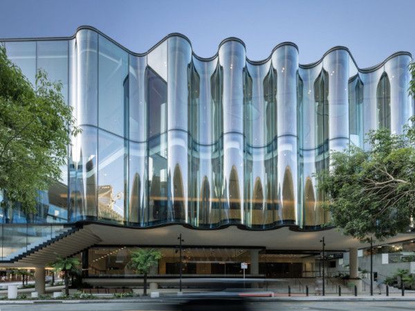
The Glasshouse Theatre Brisbane features a highly complex corrugated all-glass façade composed of alternating convex and concave curved insulating glass units with radii down to 1.0 m and panel heights up to 7.2 m. The realization of this geometry required precise control of fabrication tolerances, structural behavior and installation-induced deformations, as achieved through the engineering and execution by seele. The façade system is based on a discreet steel substructure with glass fins and structural silicone glazing (SSG) connections, enabling load transfer without visible mechanical fixings while maintaining a high degree of transparency. Parametric 3D modelling formed the basis of an integrated digital workflow, ensuring consistent geometric control from design through fabrication to installation. Finite element models incorporating geometric nonlinearity were developed to assess the structural behavior of curved glazing units and SSG joints under combined wind, thermal and installation loads. Full-scale mock-ups and digital measurement techniques were used to validate geometric accuracy, optical quality and interface tolerances, with deviations limited to the millimetre range. A dedicated installation strategy, including pre-loading of the supporting structure and the development of project-specific lifting equipment by seele, enabled controlled assembly of the façade under complex boundary conditions. The project demonstrates how advanced digital design methods, nonlinear structural analysis and precisely coordinated fabrication and installation processes enable the reliable realization of large-scale free-form glass façades with demanding geometric and structural requirements.
1. Introduction
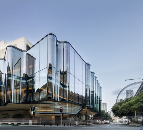
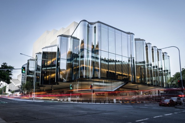
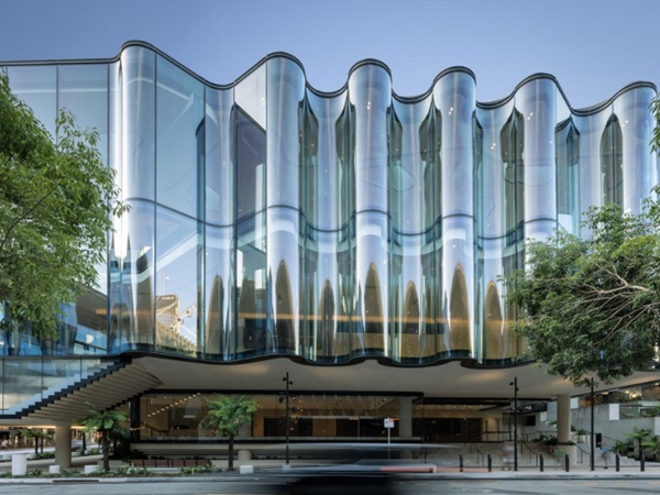
The Glasshouse Theatre Brisbane is defined by a highly transparent building envelope featuring a complex corrugated all-glass façade geometry. The architectural design combines indigenous references with contemporary façade engineering and creates a wave-like appearance through alternating convex and concave curved insulating glass units. The façade comprises 62 curved and 144 planar insulating glass units, covering an area of approximately2,300 sqm. Individual panels reach heights of up to 7.2m, while the curved units exhibit radii down to approximately 1.0m. The combination of large dimensions and tight radii introduces significant challenges in terms of fabrication accuracy, geometric compatibility between adjacent elements and structural behaviour under loading.
A key requirement of the architectural concept was to achieve maximum transparency through the reduction of visible structural components. This led to the development of a façade system based on a discreet steel substructure in combination with glass fins and SSG connections, enabling load transfer without external mechanical retainers. The resulting system required careful coordination between structural design, material behaviour and joint performance.
The realization of the façade demanded a high degree of geometric control throughout all project phases. A parametric 3D modelling approach formed the basis of an integrated digital workflow, ensuring consistency between design geometry, fabrication data and installation processes. This approach allowed for systematic management of tolerances and interfaces between curved glass units, supporting structure and connection elements.
In addition to structural design, particular focus was placed on the validation of fabrication methods and installation procedures. Full-scale mock-ups and digital measurement techniques were used to verify geometric accuracy, optical quality and interface conditions. The installation of the façade required a dedicated strategy addressing structural deformations, sequencing constraints and handling of large-format curved glass units.
This paper presents the engineering approach developed for the realization of the corrugated glass façade, with emphasis on structural system design, behaviour of curved insulating glass units, fabrication strategy and installation methodology.
2. Façade Concept and Structural System
The façade concept is based on a continuously corrugated glass envelope formed by the combination of convex and concave curved insulating glass units together with planar glazing elements. The alternating curvature generates a spatially complex geometry with continuously changing panel orientations and alignment conditions, requiring precise coordination between geometry, support structure and connections (Fig. 2).
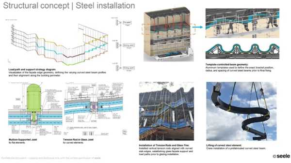
To achieve the architectural objective of maximum transparency, the structural system was designed with a reduced and visually unobtrusive load-bearing concept. The façade is supported by a discreet steel substructure consisting of vertical box beams and horizontal members, complemented by glass fins acting as stabilising elements. The arrangement of these components ensures sufficient global stiffness while minimising visual obstruction (Fig. 1).
Vertical loads of the glazing units are transferred through tension rod connections into the primary structure. The use of slender tension elements allows efficient load transfer while maintaining the transparency of the façade system. Horizontal loads, primarily wind actions, are transferred via SSG glazing connections between the glass units and the supporting structure. This approach eliminates the need for external mechanical fixings and ensures a continuous glass surface.
The interaction between curved glass units, SSG joints and supporting structure required careful consideration of load paths and deformation compatibility. Due to the corrugated geometry, variations in panel orientation led to non-uniform load distribution and local stress concentrations, particularly at transitions between convex and concave elements. As a result, the structural design incorporated detailed analysis of the coupled behaviour between glass panels, silicone joints and steel structure.
Glass fins contribute to the lateral stability of the façade and support the redistribution of loads between adjacent panels. Their integration into the system required precise geometric alignment with both curved and planar glazing units. The entire façade system was developed using parametric 3D models, forming the basis of an integrated digital workflow. This approach enabled consistent control of geometry, interfaces and tolerances throughout design, fabrication and installation. In particular, the parametric modelling allowed efficient management of the complex façade geometry and supported the coordination between individual components and disciplines.
The resulting structural concept combines efficient load transfer, geometric adaptability and minimal visual intrusion, enabling the realization of a highly transparent façade despite the complexity of its corrugated form.
3. Curved Glass Engineering
3.1. Geometry and Fabrication Constraints
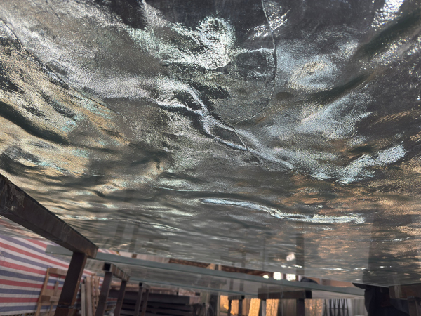
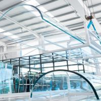
The façade incorporates both convex and concave curved insulating glass units (Fig. 3) with radii of approximately 1.0 m and 1.5 m. The panels reach heights of up to 7.2 m while maintaining relatively narrow widths of approximately 1.0 m. The alternating curvature results in a continuously changing façade geometry, leading to high sensitivity to geometric deviations and alignment inaccuracies.
In contrast to planar glazing, curved insulating glass units introduce additional geometric constraints, as fabrication tolerances directly influence both the visual continuity of the façade and the performance of the structural connections. Particular attention was required at transition zones between convex and concave elements, where local deviations can accumulate and lead to misalignment between adjacent units and supporting components.
The geometric design therefore required precise definition of reference surfaces and interface conditions. A parametric modelling approach was used to generate consistent geometry data for all façade components, enabling continuous verification of panel geometry, connection interfaces and joint dimensions throughout the design and fabrication process.
3.2. Glass Build-Up and Structural Behaviour
The insulating glass units consist of a multi-layer configuration comprising two 10 mm heat-strengthened outer panes, a 12 mm cavity, and a laminated inner pane composed of 2 × 10 mm heat-strengthened glass with SentryGlas (SG) interlayer. This build-up was selected to achieve the required structural performance while maintaining optical quality and compatibility with curved fabrication processes.
Finite element (FE) models were developed to assess the structural behaviour of the curved glazing units and their interaction with the supporting system. The glass panes were modelled using shell elements, while the laminated behaviour was represented through equivalent stiffness properties accounting for shear interaction within the interlayer.
The analyses incorporated geometric nonlinearity to capture the influence of curvature on load-bearing behaviour. Compared to planar units, the curved geometry introduces increased in-plane stiffness, resulting in reduced global deflections under uniform loading. At the same time, the curvature leads to higher sensitivity to local imperfections and edge stresses, particularly under asymmetric loading conditions.
The structural assessment considered combined load cases including wind pressure and suction, self-weight, thermal actions and imposed deformations from the supporting structure. The results demonstrated that careful control of boundary conditions and connection stiffness is required to avoid stress concentrations and to ensure uniform load transfer across the façade system.
3.3. Interaction with Structural Silicone Glazing
The behaviour of the curved glazing units is closely linked to the performance of the SSG joints, which provide horizontal load transfer and accommodate relative movements between glass panels and supporting structure.
Nonlinear numerical investigations were conducted to evaluate the coupled response of glass and SSG connections. The SSG joints were modelled using nonlinear spring elements to represent their load-deformation behaviour, allowing the analysis of stress distribution and deformation compatibility under combined loading scenarios.
Due to the corrugated façade geometry, the orientation of individual panels varies continuously, resulting in non-uniform load transfer into the SSG joints. This leads to locally varying stress states and requires precise definition of joint dimensions and properties. The analyses accounted for differential movements caused by thermal expansion, structural deflections and fabrication tolerances.
In addition to load transfer, the SSG joints contribute to accommodating geometric deviations between adjacent curved units. Their ability to absorb relative displacements proved essential for maintaining façade alignment and reducing stress concentrations at connection interfaces.
3.4. Fabrication and Mock-Up Validation
The fabrication of the corrugated façade required highly controlled manufacturing processes to achieve the strict geometric and structural requirements defined by the curved glass system.
Due to the complexity of the geometry and the fully suspended façade system, full-scale mock-ups and prototype testing were carried out during the engineering phase. These mock-ups validated critical aspects such as curvature accuracy, interface conditions between glass and supporting structure, and the dimensional requirements of SSG joints. In addition, mock-ups were used to assess installation procedures and to verify that geometric tolerances could be maintained under realistic boundary conditions.
The fabrication process was closely integrated with a digital modelling workflow, enabling direct transfer of geometry data into production. This approach ensured consistency between design intent and manufactured components and supported continuous verification of dimensional accuracy. Steel subcomponents, including fins and connection brackets, were fabricated to millimetre-level tolerances to accommodate movement, thermal expansion and cumulative geometric deviations across the façade height.
To achieve the required precision, specialised manufacturing aids such as custom templates and positioning jigs were developed for the curved steel structure, ensuring accurate placement relative to the primary structure.
3.5. Storage and Transportation Concept
Due to the dimensions, weight and double-curved geometry of the insulating glass units, a dedicated storage and transportation concept was developed to prevent deformation and damage during handling and logistics. Units exceeded 7 m in height and reached weights of approximately 2.4 t, requiring tailored solutions for both international transport and on-site handling.
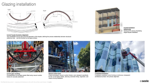
Specially designed transport frames with adjustable support points were used to accommodate both convex and concave geometries, ensuring uniform load distribution and preventing local stress concentrations. The glass units were transported in vertical orientation to minimize bending stresses, while controlled lifting procedures were defined to limit deformation during crane operations and installation handling.
Given the high geometric precision required, safeguarding dimensional stability throughout the supply chain was critical. The curved insulating glass units and steel components were sourced from specialised international fabrication partners capable of achieving the required tight tolerances and curvature accuracy. The logistics concept was therefore closely coordinated with fabrication and installation planning to ensure reliable delivery conditions and compatibility with the overall digital workflow.
This integrated approach ensured that geometric integrity was maintained from fabrication to installation, forming a key prerequisite for the successful realization of the façade system.
3.6. Installation Strategy and Deformation Management
A key innovation of the project was the development of a fully suspended façade system, in which the entire dead load of the glass and steel substructure is transferred to a top steel ring beam (Fig. 1). The realization of this concept required advanced structural modelling to calibrate load paths, connection stiffness and cumulative tolerances over the full façade height. In parallel, manufacturing processes were aligned with these engineering principles to control geometry, weight and fixing accuracy, ensuring that the installed behaviour corresponded to the design assumptions. The primary structure, including cantilevered concrete slabs, was deliberately pre-cambered to account for façade-induced deflections and to achieve the intended final geometry.
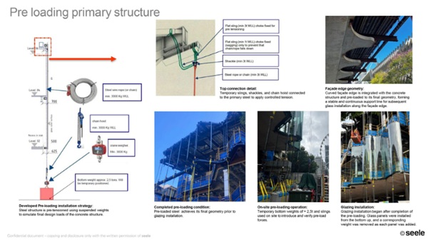
Due to the flexibility of the supporting structure and the sensitivity of the curved glazing units, deformation management played a central role during installation. A controlled pre-loading strategy was implemented to compensate for anticipated structural movements, ensuring that permanent dead load deflections were realised prior to glazing installation. The installation sequence followed a defined structural logic, beginning with secondary steel components and pre-loading operations, followed by alignment of box beams and tension rods, installation of glass fins, and finally the placement of curved and planar glazing units.
Continuous geometric verification using digital surveying methods ensured alignment between the installed façade and the design model. On-site load testing was carried out to validate structural behaviour under representative conditions. A test load of approximately 2 tonnes was applied to the primary steelwork using calibrated lifting equipment, with measured deflections between 1.5 mm and 2.5 mm, closely matching predicted values of 2 mm to 4 mm.
The installation process required careful management of tight tolerances, differential movements, temporary structural deformations and the coordination of steel and glazing works. Through the integration of structural design, pre-loading strategy, manufacturing precision and installation control, the façade was successfully realised while maintaining its intended transparency and optical continuity.
4. Discussion
The Glasshouse Theatre façade demonstrates the coordinated interaction of structural design, digital modelling, fabrication control and installation strategy required for the realization of complex curved glass systems. The project highlights how geometric complexity, tight tolerances and large-format glazing units require a fully integrated approach across all project phases.
A key aspect in achieving the required precision was the continuous alignment between digital design models and fabrication processes. Parametric modelling allowed consistent control of geometry and interfaces, while manufacturing processes were tailored to meet these requirements at millimetre-level accuracy. This ensured compatibility between glass units, supporting structure and SSG joints, despite the continuously changing façade geometry.
The project further emphasizes the importance of deformation management during installation. The combination of pre-loading strategies, pre-cambered structural elements and defined installation sequencing allowed anticipated deflections to be incorporated in advance, reducing residual movements and maintaining geometric accuracy. The effectiveness of this approach was confirmed through on-site load testing, where measured deflections closely matched predicted values.
In addition, mock-up validation and digital measurement techniques proved essential for verifying interface conditions, fabrication quality and installation procedures. These processes enabled early identification of deviations and ensured consistent quality throughout production and assembly.
Overall, the project illustrates that the successful realization of complex free-form façades is not defined by individual components, but by the precise coordination of structural behaviour, fabrication tolerances and installation processes within a unified engineering workflow.
5. Conclusion
The Glasshouse Theatre Brisbane demonstrates the successful realization of a geometrically complex all-glass façade through the integration of structural design, digital modelling, precise fabrication and controlled installation processes. The project required consistent management of geometry, tolerances and structural behaviour across all stages, ensuring alignment between design intent and built outcome.
Particular importance was placed on the coordination between engineering assumptions, manufacturing accuracy and installation methodology. Pre-loading strategies, controlled sequencing and continuous geometric verification enabled effective management of structural deformations and ensured the required level of precision despite challenging boundary conditions.
A decisive factor in the successful delivery was the close coordination between all project participants, allowing interfaces between glass, steel and SSG components to be resolved efficiently and reliably throughout the project.
The approaches developed and applied in this project demonstrate how complex façade geometries can be translated into buildable and high-performance systems. They may provide useful references for future projects involving large-scale curved glazing, where structural performance, geometric precision and visual quality must be achieved simultaneously.
Acknowledgements
The authors would like to thank all project partners, fabrication teams and installation personnel involved in the successful realization of the Glasshouse Theatre Brisbane façade.
References