This paper was first presented at GPD 2025.
Link to the full GPD 2025 conference book: GPD_2025_ConferenceProceedingsBook.pdf

Authors: Filippo Gerin a,b, Alberto Consolaro a, Massimo Maffeis a, Gianni Royer Carfagni b
a. Maffeis Engineering SpA, Solagna (VI), Italy
b. Department of Engineering for Industrial Systems and Technologies, University of Parma, Italy
Abstract
A main challenge in laminated glass design is determining the degree of shear coupling between the glass piles through the interlayer, which leads to behavior somewhere between the monolithic limit (perfect coupling) and the layered limit (free-sliding glass layers). The warping of cross-sections caused by significant transverse shear strains in soft interlayers makes traditional laminated plate theories based on the plane-section assumption unreliable. Many commercial software packages exist to assist with this, but they often have limitations, particularly with geometric nonlinearities. Some of these programs only incorporate second-order theories, which are insufficient for thoroughly analyzing curved structures. Here, we introduce an in-house developed FEM code, which employs a nonlinear theory based on solid-shell models to overcome these limitations. Our code applies the quasi-elastic approximation, where polymers are linear-elastic materials with a secant shear modulus depending on temperature and time. The geometrically exact solid-shell finite element approach allows us to use one single element per layer (glass or polymer) in the thickness direction but can also accommodate the multiple sheets in multi-material interlayers, used to impart hybrid characteristics to the laminate. Visual programming tools can import any curved geometry into the model, which approximates elements using displacement nodal values on the top and bottom surfaces of each layer with inherent regularity. An alternative solid-shell model with fewer parameters is derived by enforcing equal finite rotation of the rigid layers at each surface point through a local rotation-free re-parametrization of nodal displacements and by imposing plane stress conditions. This approach, which facilitates coupling with a solid discretization for modelling connections, is based on a straightforward strain measure quadratic in the displacement unknowns, suitable for handling finite strains. Comprehensive numerical examples for LG plates and curved shells with large deflections are included to illustrate the code potentiality.
Article Information
- Published by Glass Performance Days, on behalf of the author(s)
- Published as part of the Glass Performance Days Conference Proceedings, June 2025
- Editors: Jan Belis, Christian Louter & Marko Mökkönen
- This work is licensed under a Creative Commons Attribution 4.0 International (CC BY 4.0) license.
- Copyright © 2025 with the author(s)
1. Introduction
Laminated glass is composed of alternating layers of stiff materials (glass plies) and soft materials (interlayers). The significant disparity in their mechanical properties causes uneven warping of the cross-sections under bending. As a result, homogenized models, such as first-order or higher-order shear theories for laminated plates, fail to accurately predict structural behavior in terms of deflection, stress distribution and buckling. Specifically, the glass layers act as plates or shells, exhibiting both membrane and flexural stiffness, while the thin, soft interlayer connects them through its shear stiffness. This interaction enhances the overall bending capacity of the laminate, which lies (Norville et al., 1998) between the lower bound of freely sliding glass plies (layered limit) and the upper bound of fully bonded glass plies (monolithic limit). Consequently, cross-sectional warping is most irregular at the layered limit and virtually nonexistent (no warping) at the monolithic limit. Accurately modeling the actual degree of shear coupling between glass plies via the interlayer is one of the most extensively researched topics in glass engineering.
Various approximate engineering methods have been used, most of which introduce the concept of effective thickness—defined as the thickness of a monolith that exhibits equivalent bending properties in terms of stress and deflection. One such method is the Enhanced Effective Thickness (EET) approach (Galuppi & Royer Carfagni, 2012), which is also referenced in the updated version of the Eurocode for structural glass (Feldmann et al, 2023). This method is based on a variational approach that assumes that the deformation shape mirrors that of a monolithic plate. However, these methods are grounded in linear elasticity theory, making it difficult to account for geometric nonlinear effects. Additionally, their accuracy diminishes when applied to highly asymmetric laminated plates or under pseudo-concentrated loads.
Laminated glass is most frequently analyzed using specialized software. One of the most widely utilized tools in design practice is undoubtedly SJ Mepla. The theoretical foundation for its implementation (Bohmann, 2018) prescribes to discretize each stiff layer into Mindlin–Reissner finite elements, with independent rotations and in-plane displacements. The transverse displacement is assumed to be uniform across all layers, while the kinematics of the soft layers are derived from the variables of the stiff layers, assuming perfect bonding and negligible thickness strain. However, the software has certain limitations: it is restricted to flat geometries; the model is only second-order accurate and not exact for large deformations; the nonlinear solver is load-controlled, making it unsuitable for general instability problems.
Here, we introduce a novel approach developed within a Finite Element Method (FEM) framework, based on the theory of solid shells for plates as initially proposed by Liang and Izzuddin (2015). This model represents an advanced Mindlin–Reissner formulation that integrates independent in-plane displacements of the soft layers, with the equal rotation of the stiff layers treated as a direct variable. The study also introduces a locking-free shell finite element, and the geometrically nonlinear model is formulated using the co-rotational approach, which is particularly effective for small strain scenarios (Felippa and Haugen, 2005). Further developments, especially in the modeling of creep behavior in viscoelastic interlayers, are thoroughly discussed in Liang et al (2016), but rheological aspects will be addressed only in a future version of the code.
This model offers a simple and practical way to analyze laminated glass, as well as other laminated structures characterized by an alternating sequence of stiff and soft layers. It overcomes the limitations of small-displacement analysis and the Kirchhoff assumption, which neglects transverse shear strains in the stiff (glass) layers. The displacement field is represented using standard polynomial shape functions, as the weak formulation does not require C1 continuity—a condition typically achieved only through specialized finite element techniques or isogeometric analysis (Leonetti et al, 2019). The code offers a comprehensive nonlinear geometric description of the deformation, rather than relying on a second-order approximation, feasible only for flat geometries, as with SJ Mepla. This capability enables the code to effortlessly handle curved geometries, which can be directly imported from visual design platforms such as Rhinoceros Grasshopper.
2. The solid shell model
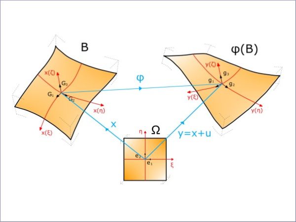
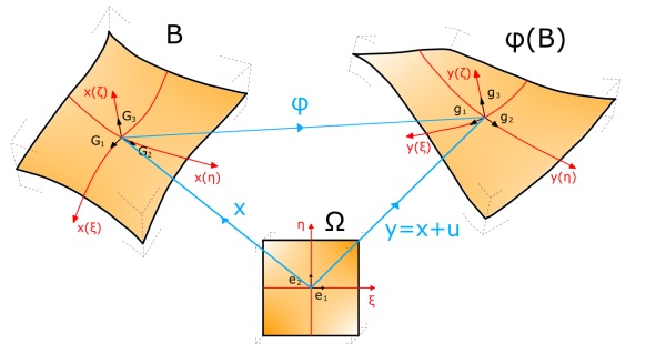
The theory underlying the specialization of the solid shell model to laminated glass are more comprehensively explained in (Magisano et al, 2023). As indicated in Fig. 1, The undistorted reference configuration of the shell is described via the convective curvilinear coordinates 𝝃 = [𝜉, 𝜂, 𝜁], with (𝜉, 𝜂) representing the middle surface and 𝜁 ∈ [−ℎ𝑖/2, ℎi/2] the thickness coordinates for the i-th layer of thickness ℎ𝑖. Such geometry can be automatically imported from design platforms. The position of the point 𝐲(𝝃) in the distorted configuration is given in terms of its position 𝐱(𝝃) in the reference configuration and the displacement 𝐮(𝝃) as 𝐲(𝝃)= 𝐱(𝝃) + 𝐮(𝝃).
The solid shell assumption consists in a linear through-the-thickness approximation, such that the position vector is given by
![]()
in terms of the bottom and top positions of the layers, respectively 𝐱𝑏[𝜉,𝜂] = 𝐱[𝜉,𝜂,−ℎ𝑖/2] and 𝐱𝑡[𝜉,𝜂] = 𝐱[𝜉,𝜂,ℎ𝑖/2]. Similarly, the displacement field is approximated as
![]()
where 𝐮𝑏[𝜉,𝜂] = 𝐮[𝜉,𝜂,−ℎ𝑖/2] and 𝐮𝑡[𝜉,𝜂] = 𝐮[𝜉,𝜂,ℎ𝑖/2] correspond to the bottom and top surfaces.
The Green-Lagrange strain tensor is then calculated via differential geometry. The constitutive equations for a neo-Hookean solid are assumed; specifically, the second Piola-Kirchhoff stress tensor is a linear function of the Green-Lagrange strain tensor through the fourth-order elasticity tensor.
FEM implementation considers an element for each layer. Since the displacement field is described by the displacements of the bottom and top surfaces of the layer, it is straightforward to consider structures composed of many layers under the hypothesis that there is no slip between them. In fact, any two adjacent layers share a common interface, whose deformation is described by the corresponding displacement vector field. In the simplest case, trilinear shape functions can be used. This approximation usually provides accurate results. In the most difficult cases, higher order shape functions can be used or, alternatively, a layer can be decomposed in sub-layers.
The linear element so defined is prone to transverse shear and trapezoidal locking, which can be eliminated by the Assumed Natural Strain (ANS) technique (Bischoff & Ramm, 1997). To avoid the thickness locking arising from the assumption of linear displacement through the thickness, the constitutive equation can be simplified using the Plane Stress Enforcement (Magisano et al, 2023).
A simplified approach involves adopting a reduced kinematic model for the laminate, where all stiff layers are constrained to maintain the same orientation during deformation, meaning the normal vector to each layer remaining identical across all layers. This simplification, usually assumed in commercial codes for laminated glass, reduces the total number of variables but also imposes the condition that the interlayer thickness remains constant. As a result, localized thickness strains in the interlayer, which can occur under pseudo-concentrated loads on laminated glass, cannot be accounted for. Anyway, for laminated shells with a small number of layers, the computational efficiency gained from this constrained kinematics is generally not essential.
3. Examples
3.1. Laminated glass plate under pseudo-concentrated load
We now present numerical experiments for a few paradigmatic cases.
Consider a 3 m × 4 m laminated glass element, composed of two glass plies, 8 and 6 mm thick, sandwiching a 1.52 mm polymeric interlayer, under a load of 5 kN, distributed on a 100 mm × 100 mm area on the top of the 8 mm glass layer. The interlayer is representative of a PVB operating at room temperature under short-term loading, for which the shear modulus is estimated as G = 50 MPa.
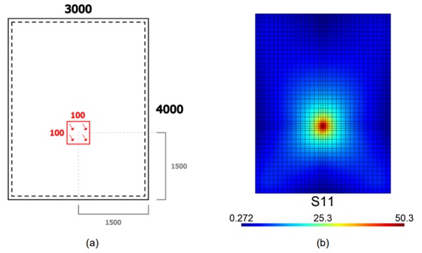
Figure 2(a) represents the layout of the plate simply supported on the four sides, with indication of the loaded area. The adopted mesh, made of 32 × 42 rectangular elements, refined in proximity of the loaded portion, is indicated in Figure 2(b). The same figure shows the maximum principal component of stress, obtained on the external tensile surface at the intrados. In this numerical experiment, we do not use the reduced kinematic model. In fact, it is necessary to consider that the pseudo-concentrated nature of the load may produce the thickness straining of the interlayer, producing a curvature difference in the deformed shapes of the two glass plies.
Results were successfully compared with those obtainable with a 3D mesh, employing 20 node brick elements, with a mesh size comparable with that of Figure 2(b), implemented in the Strand7 FE code (Strand7, 2010). Thanks to our lightweight ad hoc implementation, computation time is significantly reduced compared to software like Strand7. Our approach achieves a speedup of approximately 3× relative to the Hexa8 Strand7 simulations.
3.2. Curved laminated shell
The problem is that of a curved shell, with a radius of curvature equal to 3000 mm, simply supported on the two straight sides, as indicated in the layout of Figure 3(a). The laminated package consists of two 6 mm glass ply and 1.52 mm interlayer, for which we again assume a shear modulus equal to G = 50 MPa. The structure is subjected to the action of a 15 kN load, applied on a 100 mm × 100 mm portion.
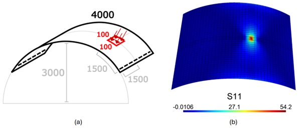
Figure 3(b) presents the result from the FEM simulation in terms of the maximum tensile surface, attained at the intrados of the laminated structures. Again, we did not apply the reduced kinematic option to properly consider the straining of the interlayer and the consequent reduction of its thickness. Comparison with the results from Strand7 (Strand7, 2010), with a 3D mesh employing brick elements with a mesh size comparable with that of Figure 3(b), demonstrated an excellent agreement. The difference is the order of 0.1 % in terms of maximum displacement and 1 % in terms of maximum stress. The computational time was 15 s for our code, about 1 min for Strand7 hexa8 brick elements, and about 9 min for the simulation in Strand7 with hexa20 elements.
3.3. Pendulum test
This problem requires a dynamic analysis, also implemented in our code. Inertial contribution is included, and the problem is discretized in time and solved using the Newmark method (Newmark, 1959).
The pendulum test, conducted in accordance with EN 12600 (CEN TC/129, 2002), is simulated using the same methodology proposed by SJ Mepla (Bohmann, 2018). The impacting mass of 50 kg is surrounded by two tires inflated to an air pressure of 3.5-4.0 bar. The model treats the mass as a pointlike object, assuming it has an initial velocity at the impact, determined by the pendulum's dropping height. The elasticity of the tires is represented by a nonlinear spring that acts only in compression, with a stiffness defined as 𝐶𝑅 = 300 + 2⌈ΔwR⌉ [N/mm], where Δ𝑤𝑅 is the spring's elongation. Since the stress state in the laminate is highly influenced by the extension of the contact area between the deformed tire and the plate surface, the force transmitted by the spring is distributed over the tire's footprint. This is calculated, at each time step, by approximating each one of the tires as a toroidal shape and determining its intersection with a plane parallel to the torus axis, positioned at a distance Δ𝑤𝑅 from the tire's outer surface.
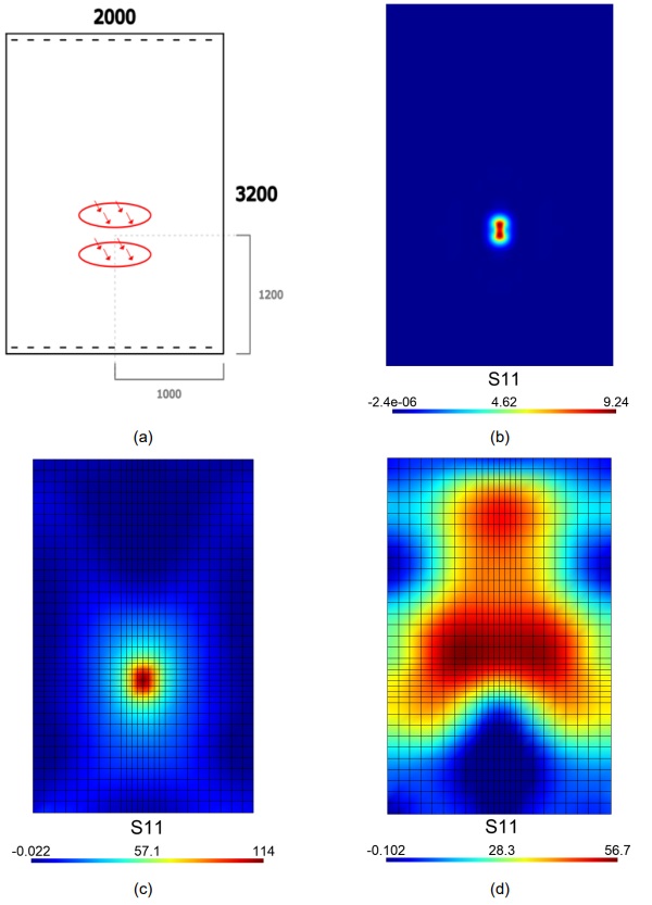
The case study is that of a 2 m × 3 m laminated glass plate, composed of two 6 mm glass plies and 1.52 mm interlayer, for which we assume a shear modulus G = 12 MPa. The stiffness of the interlayer is assumed to be very low on purpose, to test the code in the severe condition in which the interlayer is soft. As described in Figure 4(a), the plate is simply supported on the two short sides, and is subjected to the action of the impactor, described as above, with a drop height of 1 m, with center of impact at 1200 mm from the lower side of the plate. The same figure also indicates the shape of the footprint from the tires, represented by two ellipses, whose size is calculated as a function of Δ𝑤𝑅 at each time step, using the same approximation indicated in (Bohmann, 2018).
The state of stress is calculated at each instant assuming that the tires exert a uniform pressure on the current footprint, having as resultant the (non-linear) spring reaction. The difficulty in the calculation is that the size of the footprint changes in time, according to the actual value of Δ𝑤𝑅. Figures 4(b), 4(c) and 4(d) show the maximum principal stress, on the tensile surface, at various instants after the impact: (b) at t = 0.0015 s, (c) at t = 0.0195 s and (d) at 0.037 s. In state (b), the mesh is refined by doubling the number of elements on each side, allowing for a clearer representation of the imprint shape left by the two tires. The state in (c) is that of maximum stress during the analysis; here, the shape of the two tires is not recognizable, due to the diffusion of stresses in the glass ply. The case (d) corresponds to a condition in which the plate is no longer in contact with the pendulum and oscillates freely. Since the impinging tires are modelled through a non-linear spring acting in compression only, their action becomes zero when the impactor bounces back and detaches from the glass plate.
The results were compared with those obtained from SJ Mepla, demonstrating excellent agreement in replicating the full strain and stress history during the impact. The maximum displacement difference is in the order of 0.1%, while the discrepancy in maximum stress is less than 1%. Although this deviation can be deemed acceptable, it may be attributed to the fact that SJ Mepla employs only a second-order approximation for geometric non-linearities and does not account for thickness straining of the interlayer.
Naturally, our code can be extended to model the impact of the normalized pendulum on curved glass panels of any shape and size. In such cases, it will still be essential to account for the specific shape of the footprint, which will arise from the intersection of the toroidal shapes—used to approximate the tire geometry—with the initially curved surfaces of the glass. This process can be carried out based on purely geometric considerations, considering the distortion Δ𝑤𝑅 of the one-way spring that represents the stiffness of the tires.
4. Conclusions
We have briefly presented an in-house developed code that applies the solid shell model specifically to laminated glass. Its primary strength lies in its ability to accurately capture nonlinear geometric effects in laminated glass behavior, including initial curvatures. Therefore, we can equally analyze either flat or curved laminated glass, without fundamental distinction. The code is versatile, capable of analyzing laminated glass of any shape, size, and composition under diverse boundary and loading conditions. It also accounts for the dynamic response of laminated structures; the proposed examples have demonstrated the impact of a standardized pendulum as per EN 12600. Additionally, the code incorporates the thickness straining of the interlayer material, which can be significant under pseudoconcentrated loads that cause localized differential curvatures between the glass layers.
The use of this code for insulated glass units, particularly focusing on the load shearing between glass layers via the gas-filled cavity, is thoroughly discussed in a separate article presented at the GPD 2025 conference. In the present version of the code, the polymeric interlayer is modeled as linear elastic, using a secant shear modulus that aligns with the characteristic duration of the applied loads and the environmental temperature. A future update of this code will incorporate the complete viscoelastic behavior of the interlayer.
This code powers a web application freely accessible at apps.maffeis.it. The final version features an intuitive interface for defining geometry, supports, loads, and combinations, while also displaying solver results through interactive plots and generating a comprehensive calculation report in PDF format. It streamlines compliance checks with EN 16612 and ASTM 1200 standards, making the designer's workflow significantly more efficient.
Acknowledgements
F.G. acknowledges his enrollment to the PhD Program in Industrial Engineering at the University of Parma, made possible through a collaboration agreement between the Academic Institution and Maffeis Engineering SpA.
Funding declaration
This research was entirely supported by Maffeis Engineering SpA.
References
Bischoff, M., & Ramm, E. (1997). Shear deformable shell elements for large strains and rotations. Internat. J. Numer. Methods Engrg. 40 (23), 4427–4449. https://doi.org/10.1002/(SICI)1097-0207(19971215)40:23<4427::AID-NME268>3.0.CO;2-9
Bohmann, D. (2018). SJ Mepla Theory Manual, Version 5.0. SJ Software GmbH Aachen, Aachen.
CEN TC/129 (2002). EN 12600 – Glass in building - Pendulum test - Impact test method and classification for flat glass. European Norm.
Feldmann, M. et al. (2023), The new CEN/TS 18100: Design of glass structures. Glass Structures & Engineering, 8, 317-337. https://doi.org/10.1007/s40940-023-00219-y
Felippa, C., & Haugen, B. (2005). A unified formulation of small-strain corotational finite elements: I. theory. Comput. Methods Appl. Mech. Eng. 194 (21), 2285–2335. http://dx.doi.org/10.1016/j.cma.2004.07.035.
Galuppi, L., & Royer-Carfagni, G. (2012). Effective thickness of laminated glass beams: New expression via a variational approach. Engineering Structures, 38, 53-67. https://doi.org/ 10.1016/j.engstruct.2011.12.039
Leonetti, L., Magisano, D., Madeo, A., Garcea, G., Kiendl, J., Reali, A. (2019). A simplified Kirchhoff–Love large deformation model for elastic shells and its effective isogeometric formulation. Comput. Methods Appl. Mech. Engrg. 354, 369–396. http://dx.doi.org/10.1016/j.cma.2019.05.025.
Liang, Y., & Izzuddin, B. (2015). Nonlinear analysis of laminated shells with alternating stiff/soft lay-up. Composite Structures, 133, 1220–1236. http://dx.doi.org/10.1016/j.compstruct.2015.08.043.
Liang, Y., Lancaster, F., & Izzuddin, B. (2016). Effective modelling of structural glass with laminated shell elements. Composite Structures, 156, 47–62. http://dx.doi.org/10.1016/j.compstruct.2016.02.077
Magisano D., Leonetti L., Garcea G., & Royer-Carfagni, G. (2023). A constrained solid-shell model for the geometric nonlinear finite-element analysis of laminates with alternating stiff/soft layers. Applications to laminated glass. Int. J. Sol. Struct., 274, 112287. https://doi.org/10.1016/j.ijsolstr.2023.112287
Newmark, N. M. (1959). A method of computation for structural dynamics. Journal of the Engineering Mechanics Division, 85 (EM3) (3), 67–94. https://doi.org/10.1061/JMCEA3.0000098
Norville, H.S., King, K.W., Swofford, J.L. (1998). Behavior and strength of laminated glass. J. Eng. Mech. 124 (1), 46–53. http://dx.doi.org/10.1061/(ASCE)0733-9399(1998)124:1(46).
Strand7 Software (2010). Theoretical Manual, Theoretical Background to the Strand7 Finite Element Analysis System.