Article Information
- Digital Object Identifier (DOI): 10.47982/cgc.10.808
- Published by Challenging Glass, on behalf of the author(s), at Stichting OpenAccess.
- Published as part of the peer-reviewed Challenging Glass Conference Proceedings, Volume 10, June 2026, 10.47982/cgc.10
- Editors: Christian Louter, Freek Bos & Jan Belis
- This work is licensed under a Creative Commons Attribution 4.0 International (CC BY 4.0) license.
- Copyright © 2026 with the author(s)
Author:
Vladimir Marinov - Define Engineers, United Kingdom

Abstract
Cast borosilicate glass offers significant architectural potential for external façades, but its large-scale use is limited by the absence of established design data and standardised verification methods. This paper presents a performance-based methodology for thick, undulating cast borosilicate glass panels laminated to borosilicate float glass. Project-specific testing was undertaken to determine density, elastic modulus, thermal expansion and bending strength. The strength data were assessed using Weibull statistical methods, comparing EN, ASTM and weighted least-squares regression approaches. A calibrated equivalent-thickness method was developed to translate scanned three-dimensional cast geometries into practical shell models for façade analysis. Structural verification considered self-weight, wind loading, support conditions, local bracket zones and laminated glass interaction. Thermal shock risk was assessed using measured optical properties, local climatic data, solar radiation modelling and façade-specific shading scenarios. The resulting temperature differentials were converted into thermal stresses and checked against probabilistically derived material capacities. The work demonstrates a repeatable framework for combining testing, probabilistic design, finite element calibration and environmental assessment in non-standard façades.
1. Introduction
Glass has long been used in building envelopes as a transparent or translucent plate material with well-defined manufacturing processes and codified design procedures. Cast borosilicate glass changes that premise. It can provide mass, depth, texture and sculptural variation that cannot readily be achieved with conventional float glass, for instance local undulations and sharp steps of amplitude 40-50mm are not extreme for such material. However, the engineering basis for its use as an externally exposed facade material is far less mature. The material may be thick, geometrically irregular, partially opaque, optically absorptive and locally variable in thickness. Its mechanical properties may depend on casting quality, annealing regime, surface condition and defect population rather than on the standardised assumptions used for common soda-lime facade products.
This paper summarises a performance-based design framework developed for a large external facade application using cast borosilicate glass. The paper is intentionally anonymised: architectural form, project name, panel arrangement and geometry-specific information have been removed. The focus is the transferable engineering method. The aim is to establish a credible basis for design where material properties, strength distribution, thermal behaviour and structural modelling assumptions all had to be derived from project-specific evidence.
The novelty lies in the integration of four strands of work. First, the material was characterised through extensive testing rather than by reliance on published values. Secondly, the bending strength data were treated probabilistically, acknowledging that no standard characteristic strength existed for the cast material. Thirdly, the complex undulating geometry was reduced into an equivalent-thickness modelling method calibrated against solid finite element analysis. Finally, thermal shock was assessed through optical measurement, environmental simulation and thermal stress calculation rather than by prescriptive comparison alone.

2. Façade system and design challenges
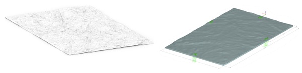
For this project an outer cast borosilicate glass layer is laminated to a thinner borosilicate float glass layer using a 3.04mm structural PVB (Saflex DG 41) interlayer. The outer cast varies in thickness between 28mm and 85mm to provide the visual mass and surface character, while the float glass ply and interlayer contributed to post-fracture integrity, composite behaviour and robustness.
The design challenges may be grouped into four categories. The first is material properties uncertainty. Before any project-specific mechanical testing had been undertaken, the manufacturer proposed T/ZBH 023—2023, Glass Panels for Architectural Exterior Decorative Use as the starting material-performance reference; however, its stated minimum bending strength of 18 MPa was unexpectedly low when compared with the 35-45 MPa characteristic bending strength typically adopted for annealed borosilicate float glass under European standards such as BS EN 3585.
The second is geometric uncertainty. Surface undulation and variable thickness result in variable locked in residual stresses stemming from differential cooling of variable thicknesses across the domain. The low characteristic strength implies that a careful analysis of the undulated geometry must be performed. The undulation also results in local stress concentrations and global stiffness variation. The third is support interaction. Again, driven by the low available bending capacity, the methods of fixing the glass back to the building are relatively limited. For instance, the glass cannot be fixed by drilling any holes or notches into it as this creates disproportionately large stress concentrations. A method of fixing with local brackets bonded with structural silicone is adopted for this project. Bracket zones and local fixing regions govern stress peaks and those must be studied in detail. The fourth is environmental exposure. The use of borosilicate glass on this project is in the form of an outer skin with overlapping panels. This shingling effect creates localised sharp shadows which combined with the broader site shadowing and the high solar irradiation result in a high risk of thermal shock which required careful consideration.
The method adopted here therefore separates the assessment into material characterisation, probabilistic strength derivation, finite element structural modelling and thermal shock verification. Project-specific test results were interpreted within the Eurocode “design assisted by testing” framework of BS EN 1990:2002+A1:2005, Clause 5.2 and Annex D, to derive resistance parameters for a material without established published design strengths.
3. Material Characterisation of Cast Borosilicate Glass
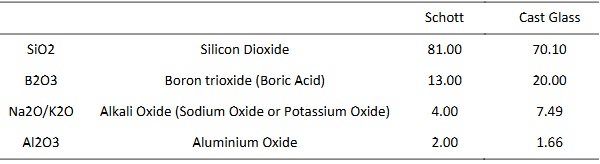
Compared with borosilicate float glass and the stated ranges within EN 1748-1-1, cast glass chemical composition shows a reduced silica content and increased boron oxide content. This is likely to reflect a casting-optimised borosilicate formulation to allow for lower viscosity and higher workability.
Table 1: Chemical composition as tested
Density was established from direct measurement of representative samples of known volume. The measured average density was found to be 2368 kg/m3. The elastic modulus was derived from the linear region of load-displacement curves measured on 10 near-flat test specimens subjected to four point bending as per EN 1288-3. Simple beam theory was used for initial back-calculation resulting in an average Young's modulus of approximately 36560 MPa (StDev 1148, CoV 3%). This value is significantly lower than the value of 60 GPa typically used for borosilicate float glass and is likely linked to the manufacturing imperfections and the presence of various imperfections.
A project-specific SCALP measurement methodology was developed as part of the production quality control regime to screen cast panels non-destructively after annealing and capture as many defective or abnormally stressed panels as possible before release from the production line. The method was used to identify residual stress patterns outside the tested production population, rather than as a substitute for mechanical strength testing.
The coefficient of linear thermal expansion was assessed from manufacturer provided data, independent testing at TU Delft and published borosilicate reference values. For design, a conservative value of 4.1 x 10^-6 /K was adopted for thermal shock calculation. This selection is the closes to the manufacturer measured values.
3.1. Probabilistic Strength Assessment
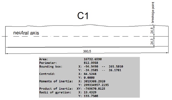
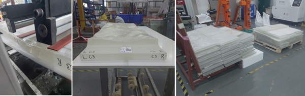
Bending strength was assessed through an extensive programme of four-point bending tests through modified EN 1288 – 3 test methodology and supplemented by full-size panel tests (2.5 x 3.8m). Due to the undulated nature of the glass the standard test methodology was modified and calibrated to suit. A series of trials were performed at TU Delft and a guidebook (project specific and not publicly vailable) was developed together with Define Engineers as relates to the proper methodology for the strength tests.
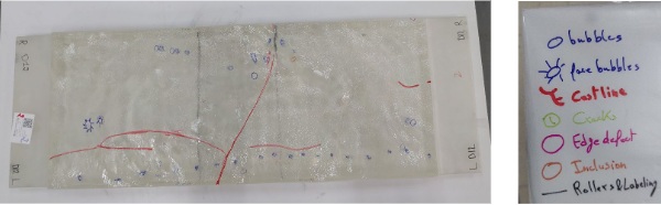
The test methodology involved crack pattern and root cause cataloguing, imperfection correlation which influenced the final manufacturing specification and quality procedure for the product. The size of inclusions and bubbles were tightly controlled on the production line based on the correlation of strength versus size and location of inclusions and imperfections. This process allowed for a balanced criteria to be developed together with the manufacturer to maintain the project programme and optimise wastage level while not deviating from the tested ranges.
The test results showed a broad distribution, as expected for a glass product governed heavily by defects. The mean strength is 19.2 MPa with Coefficient of variation (CoV) of 25%. About one third of all tested panels the crack initiated at the centre of the glass, in the other two thirds the crack originated from the edge. The full distribution was retained for lower-tail assessment, recognising that facade reliability is controlled by the weaker part of the population rather than by the mean value. A total of 82 four-point bending results were recorded as well as 4 full-size control samples were tested for size correlation.
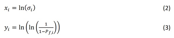
The strength results were ranked in ascending order and assigned empirical probabilities of failure using the Hazen plotting position:

Where 𝑖 is the rank of specimen and n is the number of valid test results. The data were then transformed into Weibull coordinates thus:
A two-parameter Weibull distribution was adopted in the form:
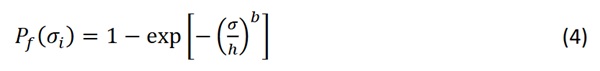
Where b is the Weibull shape parameter and h is the scale parameter. In linearised form this becomes:
![]()
The adopted statistical fit uses weighted least-squares regression with Faucher and Tyson weighting, combined with Hazen E2 plotting positions. This approach was selected because the lower tail of strength distribution governs design, and weighted fitting provides a more appropriate representation of this region than an unweighted regression of the full population. The regression minimises:

Where 𝑊𝑖 is the weighting factor and:
![]()
For the tested cast glass population, the adopted lower-tail Weibull model gave:
b = 4.12, h = 20.91 MPa, c = -12.53
The strength corresponding to any selected probability level p may be obtained from:

To assess the sensitivity of the fitted lower-tail strength, the test population was compared using several recognised Weibull fitting procedures (Datsiou, K.C. & Overend, M, 2018). These included the weighted least-squares regression with Faucher and Tyson weighting and Hazen E2 plotting positions, an alternative weighted least-squares regression, the EN 12603 GLUE approach, and a two-parameter Weibull maximum likelihood estimate consistent with ASTM C1239-13 principles. The comparison showed that the weighted least-squares and ASTM/MLE approaches provided the closest representation of the observed test population, whereas the EN 12603 GLUE fit gave a significantly poorer representation of the measured distribution and was therefore not adopted for the present assessment.
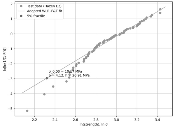
The adopted Weibull model gave a 5% fractile bending strength of approximately 10.2 MPa, which is substantially below the characteristic bending strength commonly associated with conventional borosilicate float glass. Taken in isolation, such a low characteristic value may restrict the range of feasible architectural applications for thick cast glass, particularly where large panel sizes, point supports or severe environmental exposure are required. For non-standard architectural materials, the 5% fractile may be used as a benchmark within a broader design-assisted-by-testing framework, in which the selected design value is supported by test evidence, quality control, consequence assessment and project-specific verification. In this study, the statistical strength model was therefore used not as a generic material certification value, but as part of a broader design-assisted-by-testing methodology. The experimentally derived strength distribution was combined with partial material factors, load-duration factors and façade-specific structural and thermal analyses to obtain design resistances for the relevant limit states. This approach allowed the cast glass to be assessed on the basis of its measured performance, while retaining a conservative treatment of the lower-tail strength population.
A key influence of the bending strength within the framework of EN1288-3 is the edge working. For this project, saw cutting as well as water jet cutting were considered. A 4-point bending study was carried out at TU Delft to investigate the influence of the edge working on the bending strength. It was established that waterjet cutting would have offered approximately 47% increase in bending strength (Mean 28MPa, CoV 25%) which may be beneficial in projects where cutting times can be tolerated. The cutting rate for these results was 5mm/min resulting in total machining time for the project of 28,700 hours. This was intolerable for the project programme even with multiple waterjet cutters in parallel, therefore, to meet programme the manufacturer decided on saw cut edges with hand polishing before lamination. The glass edges are saw cut inboard by about 50-100mm then ground and polished by hand. The glass back surface (laminating face) is ground back to near flat and then polished in conjunction with Kuraray’s recommendation for SGP lamination. Separate lamination tests for conformance and quality were performed which are outside of the scope of this paper.
In addition, it was found that there was little to no influence of which side of which the glass is tested, mould side (undulated) or air side (ground). This was evident from approximately 20 additional tests performed on fully ground and polished four- point bending samples (EN1288-3). Additionally, the 16 samples tested for waterjet cutting influence were alternated up or down without clear bias in strength increase. All sample results which were used in the final statistical strength calculation were tested with the undulated (mould side) in tension. The air side is laminated to another sheet of glass and as such the tensile stresses in that fibre were considerably lower in service.
4. Structural Modelling Methodology
The irregular cast surface created a practical FE modelling problem. Direct three-dimensional solid modelling of every facade panel would have captured the undulating geometry most accurately, but it would also have been computationally extremely expensive and impractical for any project related work involving repeated design iterations. Conversely, a simple flat shell model would have ignored the effect of local thickness variation and surface form on stiffness and principal tensile stress. A calibrated equivalent-thickness method was therefore developed.
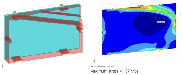
Representative cast geometries were modelled using three-dimensional solid finite elements based on scanned mould geometry.:
The mould fabrication required the Architect’s prototype clay moulds to be 3D scanned using Target-Based 3D Scanning (Global Registration / Marker Alignment). The moulds were manufactured in cast steel and 3-axis milled to match the scanned 3D geometry. The glass and the moulds were essentially identical geometries (when flipped) but it is important to acknowledge that the resulting piece of glass from each mould was cut by a range of 50-100mm from the edge of the mould after casting and before further processing. Thus the analysis of the solid 3D FE was such that the worst-case cookie cut glass was examined in an iterative fashion. Each of the approximately 20 moulds was assessed under a standardised set of support and loading conditions selected to capture adverse bracket positions and load directions. For each representative geometry, the maximum displacement and maximum principal tensile stress were extracted. Due to localised stress concentrations resulting from the peaks and throughs in the undulated surface the choice of calibrating to global deflection or local stress was based on a set of parameters. Finally, two separate zones were considered – an equivalent thickness zone in the brackets area with influence zone decided as per solid FE model (stress calibration, approx. offset around bracket of 300mm) and a global equivalent thickness in the remainder of the domain based on global deflection (stiffness calibration).
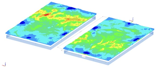
A two-dimensional shell model of constant thickness was then tuned until it reproduced the governing solid-model response. Where displacement and stress calibration gave different equivalent thicknesses, the more onerous stress-based calibration governed.
This produced a practical shell modelling basis for the global facade assessment. The approach retained the structural significance of the cast surface without requiring every analysis case to be run as a high-resolution solid model. Separate equivalent properties were used for general panel regions and local support zones with local interlayer influence zones within the same large scale model capturing each elevation of the facade. A futher advantage of this technique was that the classical approach of having separate local and global separate models was avoided.
The modelling methodology is intentionally on the safe side to account for small manufacturing variations in thickness. It does not claim that an equivalent shell model reproduces every local solid stress feature. Rather, it provides a calibrated engineering simplification that can be used transparently and efficiently at facade scale.
5. Thermal Shock Methodology
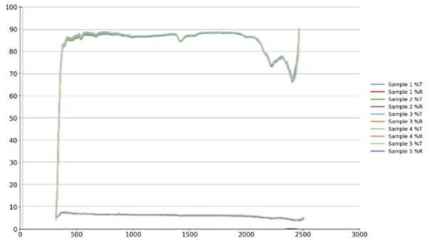
Thermal shock assessment was carried out for the scenario of high temperature differential generated between shaded and exposed glass areas during a cold winter morning. The optical properties of the cast borosilicate glass and the full laminated build-up were first established from measured spectral data (TU Delft lab), allowing solar absorption to be represented for the actual material rather than inferred from standard float-glass values.
Hourly climatic data were then used to define the relevant environmental boundary conditions, including ambient temperature, direct solar radiation and diffuse solar radiation. The terrain topography, and all surrounding buildings were modelled in Rhino 3D and detailed solar sun path analysis was performed via Grasshopper + Ladybug. Solar exposure was calculated over a representative year, accounting for orientation, inclination, self-shading and surrounding obstructions. The resulting annual dataset was filtered into critical temperature/radiation combinations using ambient-temperature bins and the most onerous solar exposure cases:
Table 2: Peak solar radiation and panel filtering table
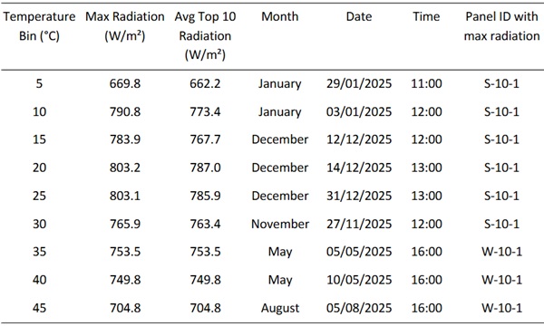
For each selected case, the temperature of the directly exposed glass region and the shaded region was calculated using the glass optical properties and appropriate heat-transfer coefficients. The thermal shock demand was defined by the instantaneous temperature differential and summarised on case by case basis for various shading scenarios.
Both still-air and wind-cooled conditions were considered, since convective cooling affects the peak glass temperature and therefore the induced stress.
The calculated temperature differentials were applied to representative finite element models to determine the resulting principal tensile stresses.
The French thermal shock guidance AFNOR NF DTU 39 P3:2006, Travaux de vitrerie-miroiterie — Partie 3: Mémento calculs des contraintes thermiques, was reviewed as a benchmark reference. However, its calculation method is principally applicable to conventional glass panes framed on four sides and is therefore not directly suitable for panels with different restraint, support or boundary conditions.
Finally, the thermal stresses were factored and combined appropriately with other relevant effects (e.g. Wind load) in the action combinations recommended in Eurocode 0. The effects were combined taking into consideration load durations. The total combined applied stress (ULS combination) was compared against the design material resistance for the relevant load duration (ULS resistance) utilising the partial load and material factors within the Eurocode limit state framework. The ULS resistance utilised the load duration factors (kmod) and material partial factor as recommended by EN 16612:2019.
5.1. Experimental Thermal Shock Validation
In addition to the solar/shading thermal shock mechanism, sudden surface cooling scenarios were considered to represent cold liquid contact with a hot glass surface, such as rain impact after solar heating, spray cooling, washing (Oikonomopoulou et al., 2018). These scenarios are different from shadow-induced thermal shock because the temperature gradient is driven by rapid convective cooling of the exposed surface rather than by differential solar absorption across the pane. The purpose of these tests was to assess whether the cast borosilicate glass could tolerate abrupt local cooling when already at elevated temperature. Submersion, partial submersion and spray-type tests were therefore used as empirical checks on the sensitivity of the material to rapid thermal gradients. A statistically significant test of partial (half) submersion of 100x100x50 blocks resisted a differential temperature of 90°C. These tests supplemented the analytical solar/shading assessment and provided additional confidence that the thermal shock evaluation covered both gradual solar exposure effects and sudden cooling events representative of rain or water contact on a hot day.
6. Results and Discussion
The results confirm that cast borosilicate glass should not be treated as a direct substitute for conventional borosilicate float glass. The measured elastic modulus and lower-tail bending strength were significantly below standard float-glass reference values, with a 5% fractile strength of approximately 10.2 MPa. This finding governed the subsequent design strategy and required a project-specific approach based on testing, statistical interpretation, and manufacturing control.
The calibrated equivalent-thickness method provided a practical means of translating complex undulating cast geometries into façade-scale shell models while retaining the governing stress response observed in solid finite element analysis. The thermal shock assessment further demonstrated that panel-specific solar exposure, shading and boundary conditions are critical for non-standard cast glass with low strength. Generic thermal shock rules for conventional four-side-framed glass were therefore insufficient, and finite element assessment using measured optical properties and realistic environmental inputs was required.
7. Conclusion
A performance-based framework has been presented for the assessment of thick, undulating cast borosilicate glass in external façade applications. The study demonstrates that material characterisation, Weibull lower-tail strength assessment, calibrated finite element modelling and thermal shock analysis must be considered together when using non-standard cast glass.
The proposed methodology provides a repeatable route for advancing cast borosilicate glass from architectural concept to engineered façade application. Future work should focus on larger production datasets, improved defect classification, factory production control and standardised guidance for structural and semi-structural cast glass products. Full scale thermal shock tests utilising solar radiation simulations in lab conditions would allow for experimental calibration of the numerical methodology described in chapter 5.
References
Datsiou, K.C., Overend, M.: Weibull parameter estimation and goodness-of-fit for glass strength data. Struct. Saf. 73, 29–41. Elsevier (2018). https://doi.org/10.1016/j.strusafe.2018.02.002
Define Engineers Ltd.: Project-specific experimental and finite element data from an anonymised external façade engineering assessment. Unpublished technical dataset/report (2026).
Galuppi, L., Royer-Carfagni, G.: Thermal and elastic modeling of architectural glass unevenly heated by the environment. Formal symmetry from Biot’s variational principle. Int. J. Solids Struct. 277–278, 112329. Elsevier (2023).
Galuppi, L., Haydar, A., Royer-Carfagni, G.: Specialization of a new flux-based approach to thermal problems. Numerical study of glass façades of buildings with cast shadows. J. Build. Eng. 98, 110949. Elsevier (2024).
Galuppi, L., Maffeis, M., Haydar, A., Royer-Carfagni, G.: Innovative FEM for the thermal analysis of architectural glazing exposed to solar radiation. Proposal for a simplified engineering approach. Glass Performance Days 2023, Tampere,
Finland (2023).
BSI: BS EN 1288-3:2000. Glass in building — Determination of the bending strength of glass — Part 3: Test with specimen supported at two points (four point bending). British Standards Institution, London (2000).
BSI: BS EN 16612:2019. Glass in building — Determination of the load resistance of glass panes by calculation and testing. British Standards Institution, London (2019).
BSI: BS EN 410:2011. Glass in building — Determination of luminous and solar characteristics of glazing. British Standards Institution, London (2011).
BSI: BS EN 3585:1998. Borosilicate glass 3.3 — Properties. British Standards Institution, London (1998).
AFNOR: NF DTU 39 P3:2006. Travaux de vitrerie-miroiterie — Partie 3: Mémento calculs des contraintes thermiques. Association Française de Normalisation, Paris (2006)
Oikonomopoulou, F., Bristogianni, T., Veer, F. A. and Nijsse, R. (2018). “The construction of the Crystal Houses façade: challenges and innovations.” Glass Structures & Engineering, 3, 87–108.