This paper was first presented at GPD 2019 by Julia Schimmelpenningh from Eastman Chemical Company.
The question of how much vertical slip or “creep” an unsupported glass layer (ply) would exhibit is frequently asked. A test method to assess creep performance in laminates has been created since no international standard exists and in-situ data is difficult to obtain. Laminated glass specimens having a size which is safe and easy to handle are subjected to a test method which allows the front glass layer (ply) to remain supported only by the interlayer.
The interlayer creep test method, and results of subsequent testing of various laminated architectural glass products are presented in this report. Laminated specimens were subjected to high temperatures over an extended period of time and the resulting change in glass alignment is reported, thus providing a measure of creep which has occurred under test conditions. The test method development, creation of test fixtures, evaluation of various interlayers having common thicknesses and the effect of glass thickness on creep was examined. Test results demonstrated that conventional interlayers have some amount of creep over the test duration while stiff PVB interlayers do not exhibit creep under the conditions tested.
Background
Laminated glass panels installed in structurally glazed applications may, at times, not have full glass thickness support along the laminate bottom edge. This can result is a displacement of the outer glass layer (ply) compared to its original position, deemed glass “creep”. The question of how much creep an unsupported lite would exhibit is a frequently asked question when installation methods are designed which do not fully support glazing. Although computer simulations have been carried out in order to calculate interlayer deformations in laminated glass for such applications, the analysis is complicated and yields conservative results with larger creep values based on the findings of this study (D’Haene1).
Since no international standard exists on how to conduct a test and in-situ data is difficult to obtain, a test to measure creep in a simulated unsupported laminate configuration has been created. The hypothesis of this test is that a fixed area and aspect ratio of laminated glass under controlled test conditions will yield results extractable to full size panels since the area of interlayer adhering to the glass will increase in accordance with the glass size.
As such, laminated glass having a size safe and easy to handle were subjected to a test method which allows the front glass to remain supported only by the polymer interlayer while the back glass is fully edge supported. The panels are then subjected to a constant high temperature and the amount of displacement of the front glass from the original position, or creep, is measured.
The degree of vertical movement may depend on several parameters including time, temperature, the thickness (weight) of the unsupported glass panel, interlayer type, interlayer thickness, and interlayer rheology. An important parameter determining the deformation of the polymeric interlayer is its rheological behavior. An instantaneous, followed by a continuous, deformation or creep occurs when a viscoelastic material is subjected to a shear deformation and is typical for most polymeric materials.
Eastman has completed an evaluation of creep for laminated panels using both simulation (D’Haene1) and physical testing by the method described in this paper. This evaluation was completed on several interlayer types, thicknesses were as available from manufacturers or those deemed as “commonly used“ in the market when several thicknesses were available. The objective of the testing was to create a reproducible physical laboratory test method that would provide directly measured data of a unsupported glass creep for laminated architectural glass in vertical applications. This data has been generated for various scenarios and related back to simulation information where possible.
Methodology
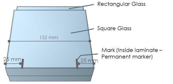
Dissimilarly sized laminated glass specimens (Glass 1: 152mm x 152mm; Glass 2: 152 mm x 172 mm;Figure 1) were constructed following interlayer supplier recommended practices. Glass alignment of the bottom edge during specimen preparation is critical. Laminates were trimmed flush, with no interlayer being attached to the extended top tab of the glass and no interlayer wrapping around the bottom edge as a means of false support. Post autoclave trim was completed as necessary. The interlayer was marked during assembly along the bottom (i.e., even glass edge) using permanent marker to ensure consistent measurement locations throughout the test.
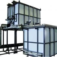
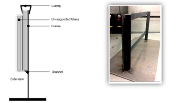
The specimens are placed on specially fabricated frames. The supported glass sits on a small fin (~ 3mm) that is designed to support only one glass of the laminated glass construction (Figure 2). The laminates are attached to the rack with a clamp which holds only the extended tab of the larger, rectangular glass and does not contact the laminated glass portion. The glass is positioned 90° vertical with no slope of the specimen permitted.
The mounted glazing and frame is then subjected to high temperatures over an extended amount of time by placing the entire system in the oven. The resulting change in distance between the two glass layers (plies) is measured and recorded, indicating the amount of creep having occured under the test conditions. Three (3) specimens of a given construction are tested as a sample set and the resulting data is averaged in the reported results.
Glass thicknesses and interlayer configurations evaluated by this test included: 3 mm, 6 mm and 10 mm glass laminated with conventional and high-performance interlayers. Thinner glasses were not tested as predictiive models and previously presented information such as D’Haene¹ and Froli² suggest limited movement that was deemed ‘immeasureable“ by this method for glass thicknesses <3mm. After the initial round of testing was completed, it was deemed acceptable to test using only the 6 mm glass thickness as it was able to initate creep and was more easily processed than the thicker glasses.
Laminates were heated in an oven at 100°C for 1000 hours to elicit creep development with measurements taken at 24, 100, 250, 500 and 1000 hours heating time. The temperature for this study was specifically chosen for multiple reasons: (a) it is at a temperature at which hydrogen bonding weakens due to molecular vibrations, (b) it is sufficiently above the temperature expected for highly absorbant spandrel or dark glass (~2% Visbile light transmittance) in extreme climates (55°C day, no wind, glass surface temperature of 75°C) and (c) it is the standarized test temperature established by all safety glazing standards for laminated glass (bake or boil tests) deemed to demonstrate proper lamination and durability.
Data collection
Laminates were assessed for creep of the unsupported glass layer (ply). The change in position between the front glass (ply) and the supported back glass (ply) over time are measured in millimeters (mm). Measurements were made initially at the zero time interval and at the designated durations with heat exposure. The initial value, if present, is subtracted from the value measured at each designated interval to give an absolute offset of the unsupported glass (ply) during that testing segment.
The final offset value is reported at 1000 hours. A visual assessment of the laminate is also completed at each interlayer with notes of any bubbles, their location, discoloration or other anomalies. The values were collected individually and then averaged. In no case was there a deviation between the measurements taken at the left and right side marks of a laminate, or among specimens of a sample set during this test for the PVB interlayers.
Measurements were made after 24, 100, 250, 500 and 1000 hours of heat exposure. The specimens were removed from the oven and allowed to reach ambient condition (minimum 30 minutes) while remaining on the racks in an undisturbed condition prior to measurement. This was done to ensure safe handling, minimize thermal shock and reduce the potential of mechanically forcing artificial creep into the specimens.
When cooled, the specimens were removed from the racks, laid horizontally on a benchtop, measured, re-set on the racks and replaced into the oven for continued exposure until the next or final interval was reached. Interval rating was done to minimize the time out of the oven and keep to predetermined rating segments. The laminate edges and any deformation were measured at the previously marked locations and captured digitally. Any visual defects such as bubbles, delamination or color change were also recorded.
Samples Tested
The following laminate configurations were tested in this portion of the study:
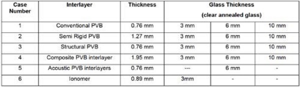
The total number of configurations was 14. A total of 42 laminates were tested with three laminated glass specimens for each case. The laminates were constructed with the defined interlayer configuration for each case in clear annealed glass. All panels were vacuum bag deaired and autoclaved in the horizontal orientation.
Test Equipment
This test requires an oven capable of maintaining a consistent temperature of 100°C ±2°C, clamps, a calibrated metric ruler and a test frame capable of holding the sample in the vertical (90 degree) orientation by supporting only the interior or inside piece of glass while ensuring that the exterior or outside piece of glass is completely unsupported except by the interlayer.
Results
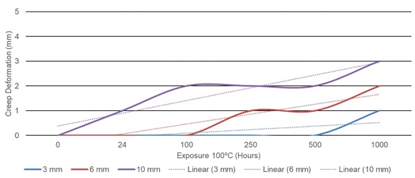
The measurements of each sample set are included as Figures 3 through 8.
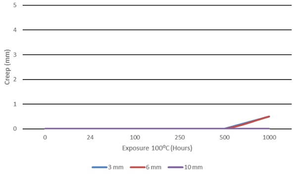
The following graphs show the trends for those laminated glass configurations with conventional PVB interlayers at 0.76 mm (Case 1) exhibiting creep during this test.
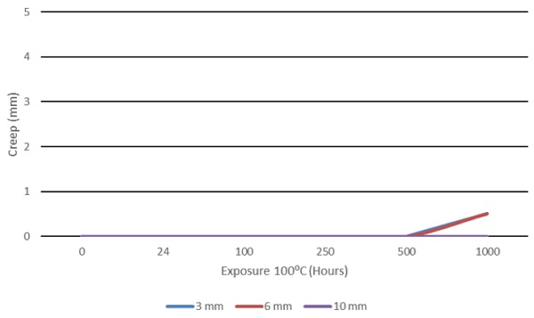
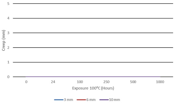
The following laminate configurations containing semi-ridgid PVB and composite PVB-PET interlayers had creep deformation for all glass thickness at 1mm or less. The laminates containing structural PVB interlayer showed no creep deformation of the unsupported glass.
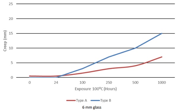
The acoustic and ionomer interlayers tested as laminates demonstrated significant creep deformation (Figures 7 and 8). The two acoustic PVB interlayers showed creep as expected based on the rheology of the products. These were tested with 6 mm glass only. The creep began to increase at 100 hours and progressed until the end of the test for both types.
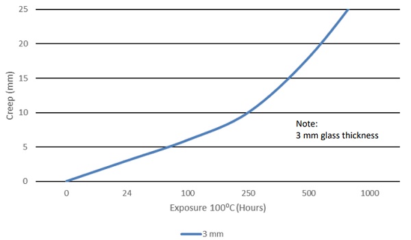
The ionomer (Figure 8) showed significant creep begining at the first rating period with only 3 mm glass. One difference between ionomer and PVB samples was the inconsistent side to side creep of the ionomer when compared with the other interlayers tested. One ionomer sample set exhibited the maximum distance of creep physically allowed by the frame (134mm), leading to discontinuation of testing for ionomer laminates with unsupported glass thicker than 3 mm.
Additional Studies
Additional studies were run at 50ºC and 65ºC to investigate the effect of exposure temperature on creep. Laminates containing conventional or structural PVB formulations at various interlayer thicknesses from 0.76 mm to 1.52 mm were tested. The unsupported glass was 12 mm thick for the 50ºC test and 6 mm thick for the 65ºC test (testing dictacted by projects). Zero creep was recorded after 1000 hours. The data was consistent for all interlayer thicknesses tested.
Studies were also conducted varying the overall glass dimensions to verify the theory of upscaling the results. The standard test size has 100 mm² of laminated area and samples with 200 mm² and 1200 mm² were added for this test. All interlayers were tested with a single type of acoustic PVB as it was determined that this interlayer would show movement. The test was run at 100ºC for 1000 hours. All panels showed nominally the same level of creep (within ± 1 mm) when compared to the smaller samples of the same configuration, suggesting the theory of scaleup from the test data is valid.
In order to assess the rate of heat gain in the laminate on this test, highly absorbing, very dark (0% visible light transmittance) interlayer, white interlayer and control clear interlayer were also tested for 1000 hours exposed at 100ºC. There was no difference noted in the time to creep or the amount of creep between the various products. The products tested were conventional PVB formulation with and without colorants.
Moisture content of the PVB interlayer was also examined with moisture content target of 0.2, 0.4 and 0.8%. All interlayer thicknesses were 1.52 mm using conventional PVB formulation. There was no creep deviation based on moisture content of the sheet.
No visible defects, such as bubbles or delaminations, were seen in any of the laminates tested. Edge discoloration was inconsistently noted in some samples at 1000 hours when exposed at 100ºC.
Conclusions
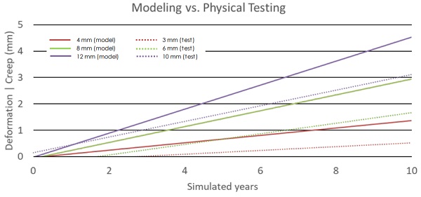
In comparing the physical test data from this study to the computational details presented by D’Haene in 2001(1), there seems to be reasonable agreement and verification of the modeling being conservative (predicting greater amount of creep) versus physical testing. One limit of the physical testing is the accuracy of measurement in less than 1 mm increments, however, this can likely be improved with the use of microscopic analysis.
The chart below (Figure 9) is a combination of a regenerated Figure 11 from D’Haene showing computer modeling of creep, overlayed with linear fit trends from the physical studies conducted and reported in this paper. Although the glass thicknesses are not identical, it can easily be seen that the data tracks well and is consistent with the 10 year data previously presented from modeling.
The modeling is interpreted using years while the test is using hours on the horizontal axis. A correlation of hours to modeling cannot be directly assessed at this point without further studies, however the ability to develop that correlation with side by side testing and modeling is evident.
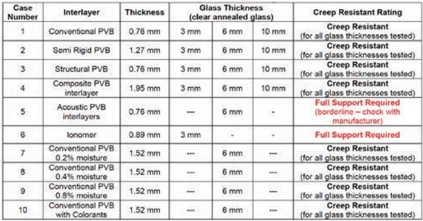
In reviewing displacement allowances from ASTM International C 11725, Standard Specification for Laminated Architectural Flat Glass and ISO 125436, Glass in building -- Laminated glass and laminated safety glass -- Part 5: Dimensions and edge finishing, the maximum allowable displacement whether due to out of square dimensioning or layer shift of glass during manufacturing is between 6 and 8 mm. Using that information as the pass/fail criteria for creep, allowance was set at 6 mm.
The assessment of creep greater than 6 mm occurring at any time during the testing, be it consistent across the laminate or sloped across the edge, shall be deemed as an interlayer that requires full edge support during installation and is assigned as: “Full Support Required”. All other laminates exhibiting less than 6 mm creep from origin shall be designated: “Creep resistant” (see Table 2).
Laminated glass with an unsupported glass layer (ply) can be tested through the devised protocol, allowing for an assessment of creep for the configuration. This method is suitable for the measurement of small laminated glass test specimens specifically created to examine creep of an unsupported glass in laminated architectural glass in vertical applications.
This test method yields non-adjusted data for laminates with designated glass thicknesses, interlayer types and thicknesses for designated durations. Test temperature of 100ºC yields consistent results and is consistent with test temperature for durability testing of laminated glass. Although well extended in duration over traditional quality testing of bake and/or boil, the temperature removes adhesion as a variable in the test as it is above the hydrogen bonding temperature and is realistic for laminated glass in applications particullarly those with absorptive qualities or high heat exposure.
Differences in the amount of creep vary by interlayer type, glass thickness and duration of exposure. Further studies may be needed to evaluate lamination and exposure variables, however conventional formulation PVB, semirigid and structural PVB all perform well. Acoustic PVB interlayer exhibits creep as does ionomer interlayer and both should be fully supported in use.
Physical testing seems to correlate well to previously reports deformation modeling.
Recommendations
Additional testing to further examine processing parameters of laminated glass and the use of unsupported glass thicknesses up to 19 mm should be completed. Also, the test temperature could be varied to examine potential creep of the products when subjected to cyclical climates. Glass with coatings, frits and printing could also be examined. Further correlation with modeling and the rheology of interlayer products will also be considered.
References
1. Structural Glazing – Creep Deformation of PVB in Architectural Applications, Dr. Pol D’Haene, Solutia Europe SA/NV Glass Processing Days, 18–21 June 2001 www.glassfiles.com
2. Adhesion, creep and relaxation properties of PVB in laminated safety glass, Prof. Ing. Maurizio Froli, Dr. Ing. Leonardo Lani, Department of Civil Engineering, Structural Division, University of Pisa, Via Diotisalvi 2, Pisa -Italy
3. D’Haene, P., Savienau, G., Mechanical properties of laminated safety glass – FEM study, Glass Performance Days 2007, Tampere, FI. 4. Viscoelastic properties of polymers, J.D. Ferry, J. Wiley & Sons, 2nd edition (1970).
5. ASTM C 1172, Standard Specification for Laminated Architectural Flat Glass, ASTM International, 100 Barr Harbor Drive, West Conshohocken, PA USA. www.astm.org
6. ISO 12543, Glass in building -- Laminated glass and laminated safety glass -- Part 5: Dimensions and edge finishing, International Organization on Standardization ISO Central Secretariat Ch. de Blandonnet 8 Case Postale 401 CH – 1214 Vernier, Geneva Switzerland. www.iso.org