First presented at GPD 2017
The changes in interlayer stiffness, adhesion and tear resistance after exposure to 3 different environmental conditions are recorded and compared to newly manufactured specimens. It was found that each environmental condition was detrimental to performance in different ways, but for each weathering condition investigated a significant deterioration was noted.
1. Introduction
Laminated glass deteriorates with time: appearance, light transmittance, mechanical properties and even chemical composition can all change when subject to different environmental conditions. The consequence of this deterioration on the post-fracture performance is unquantified, and consequently weathering is not specifically included in material safety factors for post-fracture design.
There has been some research into the impact of weathering in laminated glass. Much of this has been directed by interlayer manufacturers towards the prevention of visual defects. Recently research has been conducted into the deterioration of mechanical properties after weathering, predominantly for unfractured glass. The impact of weathering on postfracture glass is different to that of unfractured glass. Before fracture, the role of the interlayer is to transfer shear only. After glass fracture, the interlayer carries both tension and shear, and must maintain adhesion to the glass, as such this topic warrants investigation beyond the pre-fracture case.
Weathering can occur either before fracture, i.e. during the lifespan of the glass, or after fracture for example glass breakage in a humid or wet environment. Weathering after fracture is a separate topic not addressed within this work, but was published as part of a separate study [1].
This work investigates the impact on post-fracture performance of different environmental conditions by means of through-crack tensile tests on small scale PVB laminates. The changes in interlayer stiffness, adhesion and tear resistance are recorded and compared to newly manufactured specimens. It was found that each environmental condition affected post-fracture performance in different ways, but in all cases deterioration was significant and warranted further, larger scale study.
2. Existing Literature
The existing body of research can be divided into three categories: 1) That focussing on visual deterioration; 2) studies investigating change in the mechanical performance of unfractured glass, and 3) studies from the adhesive community which investigate deterioration of adhesion under different environmental exposures. Each topic is addressed in turn below.
The largest body of research into weathering has been conducted by interlayer manufacturers. The aim of which is predominantly to develop their interlayers and lamination techniques to resist visual defects. In 1998 accelerated weathering procedures for the assessment of visual performance was standardised in Europe by EN ISO 12543-4 [2, 3]. Three accelerated weathering procedures are prescribed: high temperature, high humidity and exposure to UV. Laminates must be able to withstand these procedures without occurrence of visual defects. There is no requirement for assessment of the mechanical performance after these weathering procedures.
Delincé [4] investigated changes in the shear stiffness of PVB and SG after artificial exposure to UV and high humidity. Specimens were subject to the artificial weathering procedures outlined in EN ISO 12543-4. After weathering, the specimens were tested in shear and fourpoint bending and compared to a reference set of non-weathered specimens. They found that exposure to both UV and humidity increased the stiffness of PVB marginally for the shear specimens, but decreased the stiffness in the four-point bending specimens.
Sackmann [5] also performed shear tests on PVB laminates exposed to humidity and UV-radiation. They found that UV-radiation reduced the shear modulus by about 10%, whilst humidity exposure reduced the shear modulus by as much as 50%. The reader is also directed to detailed studies conducted by Ensslen [6] who conducted shear tests on both naturally and artificially weathered specimens; Serafinavicius [7] who conducted four-point bending tests on specimens subject to the artificial weathering procedures prescribed in EN 12543-3; and Kothe [8, 9] who investigated changes in the glass transition temperature after different weathering procedures.
Recently there has been some work into the durability of interfacial adhesion. Additionally, the literature is supplemented well by research conducted on glass-specific adhesives. Louter [10] investigated changes in adhesion in steel-glass composite beams bonded with an SG interlayer after exposure to humidity and thermal cycling weathering procedures. Louter found that adhesion was reduced in specimens which had been exposed to humidity, but could not conclude if thermal cycling affected adhesion. Both Delincé [4] and Sackmann [5] found that both humid environments and high UV radiation caused a reduction in adhesion for PVB-glass laminates, whilst Goebel [11] found no reduction in adhesion in glass-EVA laminates after exposure to salt spray for 28 days.
3. Weathering Procedures
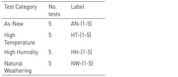
In this work 3 different environmental exposures were investigated and compared to nominally identical newly-manufactured specimens. The 4 testing categories are summarised in table 1.
Two accelerated weathering procedures were investigated alongside one “natural” weathering procedure. These were compared to tests conducted on nominally identical, newly manufactured specimens. The two accelerated weathering procedures that seek to simulate the effects of long term exposure to high temperatures and high humidity environments respectively. The procedures outlined in BS EN 12543-4 were followed for both conditions. This standard prescribes accelerated weathering procedures developed specifically for PVB glass laminates.
High Temperature: Specimens were heated in a convection oven from room temperature to 100 °C over a period of 30 minutes. The specimens were then held at 100 °C for a further 16 hours before being allowed to cool at room temperature. Once fully cooled, the specimens were tested within 24 hours.
High Humidity: Specimens were held above water in a sealed chamber heated to 50 °C for a period of 2 weeks. This creates a relative humidity of 100% within the chamber. Specimens were subsequently tested at ambient conditions (21 °C; 45% RH) within 3 hours of removal from the chamber.
Naturally weathered: Specimens were placed in an external environment in Cambridge, UK, for a period of 1 year (10th March 2013 - 10th March 2014). The specimens were positioned on a west facing surface inclined at 20° to the horizontal in an area with no shade. A sloped surface was utilised to prevent soaking of the specimens during heavy rain-fall. These conditions by no means represent a worst-case scenario, but indicate whether weathering should be a consideration for all glazing, or if it is relevant only to extreme environments.
The TCT specimens in the naturally weathered group were placed in an external environment in Cambridge, UK, for a period of 1 year (10th March 2013 - 10th March 2014). The specimens were positioned on a west facing surface inclined at 20° to the horizontal in an area with no shade. A sloped surface was utilised to prevent soaking of the specimens during heavy rain- fall. These conditions by no means represent a worst-case scenario, but indicate whether weathering should be a consideration for all glazing, or if it is relevant only to extreme environments.
4. Experimental Work
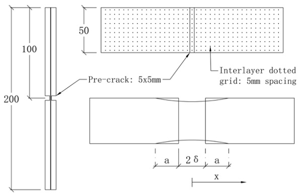
Through crack tensile (TCT) tests were conducted on 200 mm x 50 mm laminated glass specimens as shown in figure 1. The specimens were manufactured from two layers of 6 mm annealed soda-lime-silica glass, laminated with a 0.76mm Saflex RB41 PVB interlayer. A dotted grid was printed on one side of the interlayer. The lamination process was representative of standard production techniques.
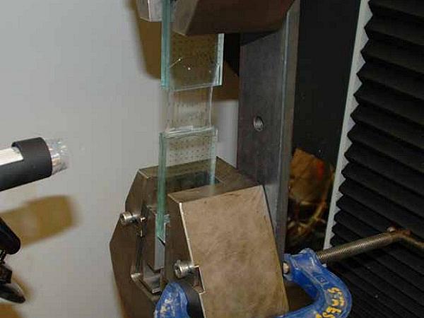
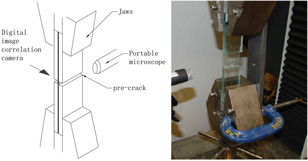
The TCT test was initially developed by Sha et. al. [12], and has since been used widely as a simple and controlled method of assessing post-fracture performance. The test set-up is shown in figure 2: the glass is clamped rigidly in an Instron 5500R universal testing machine. A tensile force is applied to the 2-ply laminate which has a single, coincident fracture in each glass ply.
The applied load is transferred across the glass fracture by the polymer interlayer which elongates, and delaminates from the glass surfaces. The specimens fail by tearing of the interlayer or by excessive delamination between the glass and the interlayer. A pre-crack was created by grinding a 5 mm wide and ≈ 5 mm deep channel across the mid- line of each glass ply using a diamond coated wheel as shown in figure 1. This process left 1mm of glass intact on either side of the polymer interlayer. The pre-crack was formed after the weathering procedure, in order to ensure that the test was a true representation of weathering occurring before glass fracture.
Slip at the interface between glass and test rig was eliminated by bonding pure aluminium plates on the glass in the region to be clamped. Whilst the test specimens were placed a small, but constant tension was applied. This prevented compressive forces causing buckling of the slender ‘pre-crack’. Once secured the remaining 1 mm of glass was fractured in tension, immediately prior to testing. This significantly reduced the occurrence of damage to the interlayer.
A displacement rate of 2δ =0.264 mm/s was applied across the fracture such that the interlayer stretched and delaminated. This speed corresponds to that used during a previous study at the University of Cambridge. Applied force was recorded by the universal testing machine. Distortion of the dotted grid was captured using a high-definition video camera at 25 frames/second. The images were analysed using the open source digital image correlation (DIC) software by Eberl [13]. Finally, the delamination front was captured throughout the duration by a portable digital microscope.
5. Results
5.1 Response of as-new specimens
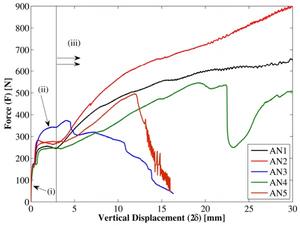
The response of the newly manufactured specimens is shown in figure 3. It can be divided into three distinct phases:
(i) Linear phase, with forces increasing to an average peak of 275 N. This phase is labelled as (i) in figure 3. The response is interrupted by a discontinuity at 160 N caused by movement in the test rig. During this phase the length of initially un-bonded interlayer stretches; little to no delamination occurs
(ii) Steady-state phase during which delamination commences and continues at a roughly constant rate. The force also remains constant. This phase, labelled as (ii) in figure 3, continues until approximately 3 mm total displacement
(iii) Failure phase - beyond displacements of 2δ = 3 mm the response varies between specimens. This has been noted previously by Ferretti [14].
Three different failure methods were observed: specimens 2 and 4 failed in tension across the delaminated interlayer; specimens 1 and 5 failed by slip between glass and jaws, both specimens exhibited large interlayer deformation prior to failure. Specimen 3 failed by interlayer tearing. This tearing occurred early in the test before significant delamination. This is attributed to a damaged interlayer, caused during glass fracture.
5.2 Response after High Temperature pre-conditioning
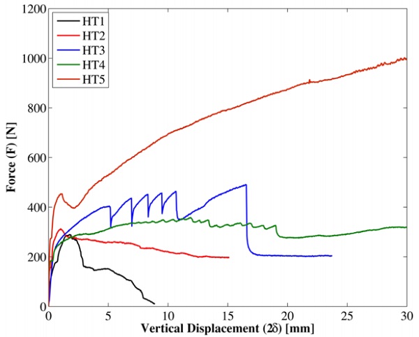
The force-displacement response of the specimens which were pre-conditioned with the high-temperature accelerated weathering procedure can be seen in figure 4. These specimens also show an initial linear response, with a peak force of 340 N. Beyond the linear phase, each specimen responded differently. As previously reported by Ferretti [14], TCT test responses are frequently very varied, even for newly-manufactured specimens.
The high temperature specimens showed a stiffer response than newly-manufactured, forces were higher and delaminated lengths smaller. Ink from the dotted grid transferred from PVB to glass, making digital image correlation difficult. Failure occurred by local tearing in specimens 1 and 2; slip at the glass- jaw interface in specimen 3; delamination in specimen 4; and global tension in specimen 5. The failure mechanisms were not significantly different to newly manufactured.
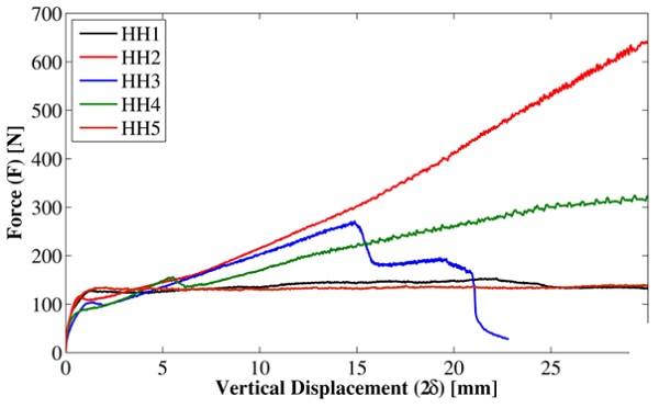
5.3 Response after High Humidity preconditioning
The force-displacement response of the specimens which were pre-condition with the high-temperature accelerated weathering procedure can be seen in figure 5. The response is markedly different to both the as-new and high-temperature categories. After the initial stretching phase, the steady-state delamination phase occurred at approximately 115 N. The delamination phase continued for significantly longer than the as-new and hightemperature specimens: specimens 1 and 5 remained in the steady-state delamination phase throughout the entire test duration.
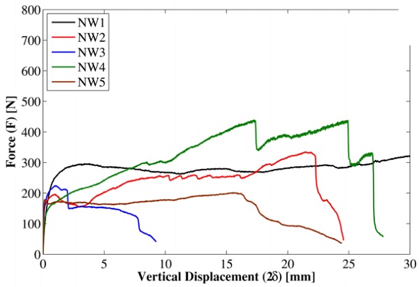
5.4 Response after Naturally Weathering
The naturally weathered specimens exhibited a lower load-carrying capacity than the asnew specimens. Steady state delamination occurred at just under 200 N, compared to 115 N in the high-humidity tests, and 275 N in the as-new specimens. The response can be seen in figure 6. Specimens 2-5 showed some uneven delamination and then tore. In previous categories, tearing was only seen when no delamination occurred, and it was attributed to interlayer damage. Specimens 2-5 all tore after delamination, suggesting a significant reduction in interlayer tear resistance.
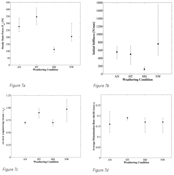
5.5 Results Comparison
Figure 7 shows a summary of the test data for each weathering category. In image (a) the average steady state force as recorded during phase 2 of the test is shown. It is clear that the high humidity environment reduces the force required to delaminate the PVB interlayer. This is consistent with previously published results [1]. In figure 7(b) the average initial stiffness of each weathering category is shown. The stiffness is calculated for the linear phase (phase 1 in figure 3) only. This stiffness is recorded before significant delamination and is therefore a measure of the effect of weathering on the bulk interlayer shear modulus. Again, the humid environment was found to be severely detrimental to performance.
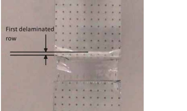
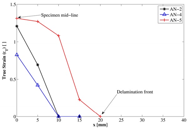
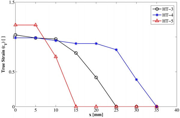
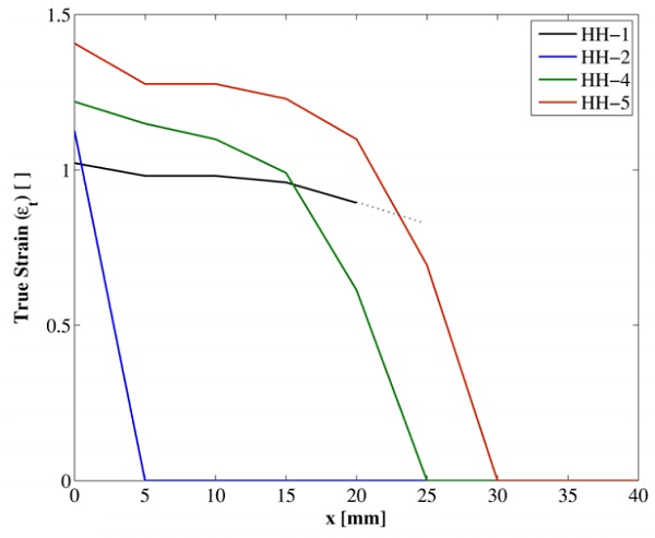
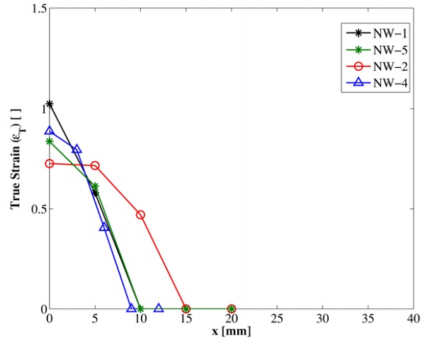
In figure 7(c) the interlayer strain causing delamination is shown. This was calculated using digital image correlation software to measure strain in the first delaminated row (see figure 7(e)), This represents interlayer strain before significant creep and can be used to assess adhesive strength after weathering. Figure 7(d) shows the delamination rate before onset of tearing. A consistent response is seen across all categories. This is a strong indicator that adhesion is strain-governed as opposed to stress-governed. Finally, DIC was used to determine the interlayer strain profile at failure.
The results can be seen in figure 8. In Figure 8 the strain profile represents a snap shot in time at the point of TCT specimen failure. The distance x represents distance, measured vertically from the specimen midline. The findings of all tests are summarised in table 2.
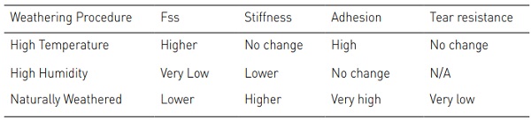
6. Discussion
The results show that the post-fracture performance is changed for each weathering condition investigated. Different weathering procedures influence interlayer bulk behaviour, interfacial adhesion, and tear resistance in different ways.
Exposure to high temperature: High temperature led to an increase in steady state force without a corresponding increase in bulk interlayer stiffness. This indicates that temperature has no effect on the bulk interlayer but increased the interfacial adhesion. Unfortunately, increased adhesion is well known to increase susceptibility to tearing.
Exposure to high humidity: High humidity led to significant reduction of interlayer stiffness. This is in agreement with the observed reduction in steady state force. It appeared that there was no change in the adhesion causing strain. This contrasts with earlier published results [1], and implies that the reduction in stiffness is sufficiently high to govern global postfracture behaviour.
Exposure to natural weathering: The specimens exposed to natural weathering recorded lower forces than those observed in the newly manufactured specimens. Conversely, both stiffness and interfacial adhesion were found to be higher than as new. This infers that the energy was being dissipated by other means – probably local large strain mechanisms that eventually led to the early tearing witnessed in this category.
These findings are reflected in the strain profile at failure shown in figure 8. The area below the strain profile curve combined with the steady state force, indicate energy dissipated by interlayer strain. The intersection with the x-axis shows the total delamination at failure.
More energy was dissipated as strain for the specimens which underwent hightemperature weathering. Both the area under the curve and steady state force are higher than newly manufactured. The observed high adhesion strength limited energy dissipated by delamination. Conversely, the total delaminated length was also higher, this suggests some increase in resistance to tearing. The specimens exposed to high temperatures, also exhibited a more symmetrical and even delamination; this could also account for the increase in total delamination.
There is an increase in area under the curve for the high humidity tests, however this is matched with a reduction in steady state force and increased test duration. From the strain profile alone it is difficult to decompose the global behaviour into the constituent bulk and adhesive parts.
The strain profile of the naturally weathered specimens shows that little energy is dissipated in both global deformation and interlayer delamination. Instead the energy is dissipated in local large strain mechanisms which eventually lead to tearing.
7. Conclusions
All weathering procedures investigated here caused a change in the post-fracture response. Humidity was found to decrease interlayer stiffness. High temperatures increased adhesion which could lead to premature tearing. The naturally weathered specimens showed a significant decrease in tear resistance.
The work highlights the need for further study, in particular for the need to investigate the post-fracture performance of full scale, naturally weathered laminates from a variety of real-world environments.
It is impossible to perform a quantitative assessment of the impact of weathering from lab based research on small scale specimens. The qualitative results presented here require real world data to inform:
1) Influence of specimen size
2) Relationship between accelerated weathering procedures outlined in BS EN 12543 and “real-world” environments.
Acknowledgements
The authors would like to thank Interpane for providing the samples for this work, and also to thank Eckersley O’Callaghan for their time and guidance.
References
[1] C. Butchart and M. Overend, “Influence of Moisture on the Post-Fracture Performance of Laminated Glass,” Glass Performance Days, Finland, June 2013.
[2] CEN. BE EN ISO 12543-4:2011 Glass in building - Laminated glass and laminated safety glass - Part 4: Test methods for durability, 2011.
[3] Norbert Wruk. A New ISO Standard for Laminated Glass. Glass Processing Days 1999
[4] D. Delincé, J. Belis, Gauthier Zarmati, and Benoit Parmentier. Structural behaviour of laminated glass elements – a step towards standardization. In Glass Performance Days 2007, pages 658–663, Finland, June 2007.
[5] Vincent Sackmann, Christian Schuler, and Holger Gräf. Testing of Laminated Safety Glass. In ISAAG 2004, pages 1–8, 2004.
[6] Frank Ensslen. Influences of laboratory and natural weathering on the durability of laminated safety glass. In Glass Performance Days 2007, volume 2, pages 584–590, Tampere, 2007.
[7] T Serafinavicius, Jean-Paul Lebet, Christian Louter, A Kuranovas, and T Lenkimas. The effects of environmental impacts on durability of laminated glass plates with interlayers (SG, EVA, PVB). In Challenging Glass 4 & COST Action TU0905 Final Conference, pages 455–462, 2014.
[8] Michael Kothe and Bernhard Weller. Influence of environmental stresses to the ageing behaviour of interlayer. In Challenging Glass 4, pages 439–446, 2014.
[9] Bernhard Weller and Michael Kothe. Ageing Behaviour of Polymeric Interlayer Materials and Laminates. In Glass Performance Days 2011, pages 240–243, 2011.
[10] Christian Louter, Jan Belis, Fred A. Veer, and Jean Paul Lebet. Durability of SG-laminated reinforced glass beams. In Glass Performance Days 2011, pages 343–347, Tampere, 2011.
[11] Horst Goebel. Laminated safety glass with EVAbased densely cross-linked interlayer: Durability, mechanical and optical properties. In Glass Performance Days 2013, pages 232–234, 2013
[12] Y. Sha, C.Y. Hui, E.J. Kramer, P.D. Garrett, and J.W. Knapczyk. Anal- ysis of adhesion and interface debonding in laminated safety glass. Jour- nal of Adhesion Science and Technology, pages 49–63, 1997.
[13] C. Eberl. Digital Image Correlation and Tracking, 2006. URL: http://www.mathworks.co.uk/matlabcentral/fileexchange/ 12413-digital-imagecorrelation-and-tracking.
[14] Daniele Ferretti, Marco Rossi, and Gianni Royercarfagni. Through-cracked- tensile delamination tests with photoelastic measurements. In Challenging Glass 3, number June 2012.