Challenging Glass 6
Conference on Architectural and Structural Applications of Glass
Louter, Bos, Belis, Veer, Nijsse (Eds.), Delft University of Technology, May 2018.
Copyright © with the authors. All rights reserved.
ISBN 978-94-6366-044-0, https://doi.org/10.7480/cgc.6.2180
Author:
Raul Corrales Marcos | BIFF SA - biffsa.ch
The aim of this paper is to explain how the design intent of a bespoke glazed façade develops from the point of view of the façade consultant BIFF SA. The explanation of this concept development is not only interesting because of the different phases of the process, but also because of the unusual specifications and demands established by the architects and the Client, and for the project evolution trough several technical solutions up to final project state. During the concept development materials like stone, steel, aluminum or fabric are normally combined with glass.
This challenging glazed façade has been developed for a luxury villa in Switzerland where a triple laminated glass cladding has been selected as the final most suitable solution for creating a building envelope with glass panes of 3000mm W x 7000mm H bonded to a back frame with structural silicone. These units have obviously aesthetic requirements and also different functional applications and the solution should fulfill all demands and do not the technical aspects of building up a façade with such a big glass units.
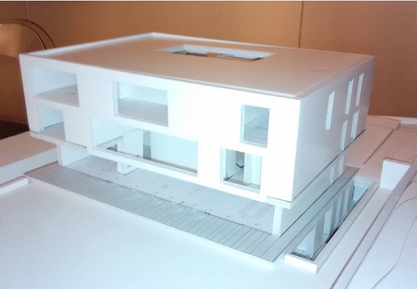
1.Building description and main façade elements
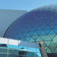
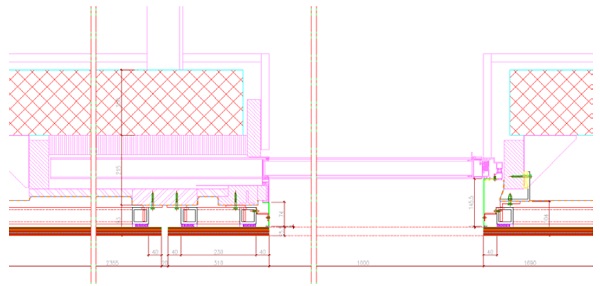
The construction project of the villa located in Switzerland is a luxury building with about 1000 m2 of façade. Theten meters high main building consists of two levels of rectangular shape, the floor level has some transparent glazed areas and opaque zones, first and second levels have transparent, opaque and opened areas (balconies). There is a step between the floor level façade (floor façade) and the upper façade (main façade), so that both façades are not in the same plane and an exterior ceiling covers the cantilever area.
In this paper we will only cover the main façade and the external ceiling because of the continuity of the cladding.
The main façade has a sort of box shape 24m wide x 13m deep x 7m high and the following type elements are identified:
- Opaque façade cladding
- Transparent double skin windows
- Transparent frameless sliding windows with glass barriers
- Large size fixed windows
- Barriers and balcony cladding
- Opaque ceiling cladding
The different façade elements are required for complying with the habitability constrains and must be considered in the envelope concept development.
2.Architect design intent
One of the main challenges of this project is to achieve the architect ́s design intent. At the beginning the client and the architect looked for a continuous façade with the minimum number of joints preliminary in mirror aspect and after in white or almost white color and with the possibility of using LED light for getting back-lightning effect during the night.
Next points indicate more details about these elements.
2.1.Continuous façade
Reducing the number of cladding joints in order to get a smooth and continuous façade is the most important point, the 7m high façade should not have horizontal joints while the vertical joints should be set out as separated as possible at minimum of 2 m.
The consequence is that standard unit sizes should be equal or bigger than 2000 wide x 7000mm high and the cladding material should be as continuous as possible at joints positions (only the cladding material should be visible).
2.2.Color and material
This is normally one of the most important points because depending on the color and texture chosen by the architect because it would have an impact on the specification of materials and potential systems.
At the beginning the client suggest to have a mirror aspect. The idea of being able to contemplate oneself in a mirror and of having the perfect image of the sky and countryside was attractive, but considering the effects of solar radiationthe client understood that it would not be the most appropriate solution.
In this case the white color was quite rapidly defined and there was not any advice about the texture. Samples in aluminum, steel, vitrified steel, fabric, composite, glass and laminated stone were presented along with the Maximum dimensions, datasheets and other technical constrains of each one of them.
2.3.Translucently
As the client wished to use LED light in order to create an effect of retro lightning, using complete opaque materials was not the most suitable solution. Opaque materials were disregarded because using the joints gap was the only way to get this effect and the joints would have to be too big (that would break the continuous and smooth façade).
Translucent materials were required and the use of glass became a must also due to of the issue of the glare, a glossy surface gas also required.
3.Material and aspect selection
Once glass was the chosen material, four different samples were presented to decide the most suitable solution and start with the façade concept development:
- Marble and glass laminated façade: Dimensions limited to 1500mm x 6000mm with intermediate edge to edge joints.
- Laminated glass with fabric interlayer: Dimensions are limited to, 2000mm x 4700mm Maximum. The main issue is the requirement of preventing moisture from damaging the glass edges.
- Ceramic fritted glass: It is possible to fabricate the required dimensions but without texture.
- Digital printed glass: It is possible to fabricate the required dimensions with the desired image of texture.
- PVB colored glass: It is possible to fabricate the desired dimensions but combining opaque and transparent areas in the same unit was really complicate.
At this stage the client took the main decision concerning the façade, the cladding material would be glass and the texture requirement was disregarded. The client selected a 100% fritted glass RAL 9010 color.
The unit dimensions were also fixed at this stage, the cladding would be made of 3000mm x 7000mm units.
4.Technical aspects
Once it was decided that a glass material would be used with 3000mm width and 7000mm high unit sizes, we could define the main technical aspects to be considered in the façade conception.
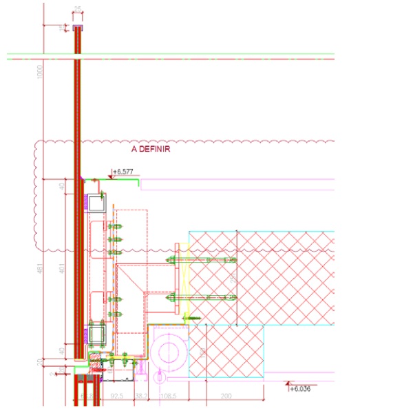
4.1.Sub-structure and insulation performance
Thermal calculations had already been carried out by our team so defining the insulations type, performance and thickness was quite simple.
Due to the complexity of the sub-structure we decided to use mineral wool as insulation material as there were many fixings back to the main structure and the mineral wool is a material that can be adapted to this arrangement.
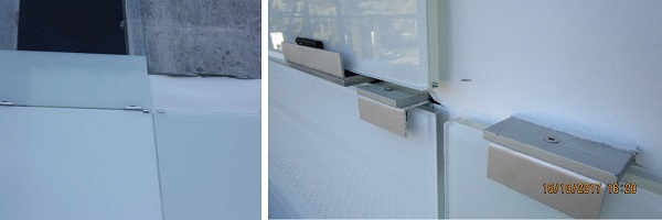
For determining the sub-structure we run several glass calculations in order to decide where the glass would need to have supports (frames). Due to all intermediate required sub-structures we also decided to integrate a white back film in the design in order to reduce the aesthetic effect of the sub-structure due to the relative translucently of the cladding.
All sub-structures and frames should be fabricated with aluminum or stainless steel to reduce metal corrosion, ironmongery and screws should be provided in A2 Stainless steel for the same reason. Thermally broken elements were also indicated to ensure the cladding thermal performance of 0.16 W/m2k.
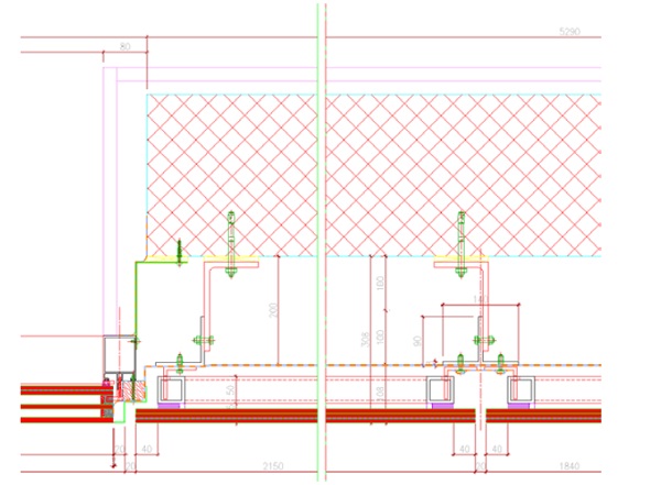
4.2.Frame
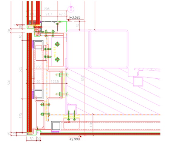
Frames should not be visible, so we needed to use a bonding frame bonded to the back of the glass. We decided to use a structural silicone system with mechanical supports withstanding the dead load, the design should be made in accordance to the EOTA requirements.
In the case of the glass ceiling these supports would be more visible because the vertical load is vertical to the façade, the support should overlap the front glass face.
The structural silicone bonding must always be calculated, in this case a specific calculation was made for assessing the minimum thickness of the bonding material in order to cope with the thermal expansion of different materials.
4.3.Glass composition
We decided to use laminated PVB glass in order to minimize the risks in case of glass breakage. It was recommended to use heat strengthened glass for improving stability under breakage conditions but also because of the lower anisotropy and optical issues compared to a full toughened solution.
Low iron glass was selected for minimizing color distortions and the opaque white RAL 9010 frit was specified in face 2 in order to reduce the visual impact of the back frame.
The glass edges should be grounded for improving the visual quality and the glass global resistance, so reducing the probability of brakeage and being able to easily assess potential issues prior installation. The edges would be fully ventilated and exposed to weather conditions.
4.4.Glass calculation
The glass cladding presents several different situations and the worst case scenario of each of them has been assessed. The main cases were indicated in the point 1 of this document, the list below shows the main situations and constrains of the standard situations.
- Opaque façade cladding: 3000mm with by 7000 high unit. Dead load, wind load and thermal load considered.
- Transparent double skin windows: Like opaque cladding.
- Transparent frameless sliding windows with glass barriers: 3000mm with by 7000 high units. Dead load, wind load, barrier load and thermal load considered. These units present pockets in the window areas placed in different positions, so different calculations were carried out to asses them.
- Barrier and balcony cladding: Specific areas with different dimensions, the most critical one is the transparent barrier requiring a longitudinal fixed connection at the bottom edge and pin connections at the top edge. Dead load, wind load, barrier load and thermal load considered.
- Opaque ceiling cladding: 3000mm with by 2000 high unit. Dead load, wind load and thermal load considered.
Once these calculations were made we were able to define the cladding glass composition: Low iron heat strengthened glass, 10+10 mm thickness laminated glass with 4x0.36mm PVB interlayer, frit on face 2 (fully or partially depending on the building position), with grounded edges.
4.5.Movements
The building does not present excessive movements, however, at the South façade there is an specific area where a 12m span carbon fiber beam supports the cladding and also a triple glazed glass unit 8m length.
This details was studied in depth so we ensured it worked for all potential movements and deflections.
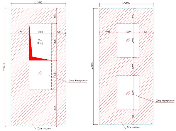
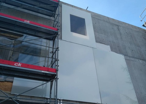
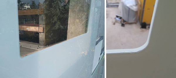
4.6.Glass pockets
The project window areas were commonly placed at the center of the big glass units, the glass cladding should be transparent at the window barrier area and there should not be any glass in the main vision area of the window. The large glass units contained glass pockets which difficulted both, calculation assessment and aesthetics as the pocket corner should not be sharp. A rounded 20mm radius corner was specified in order to reduce the stress concentration at these points.
4.7.Other technical issues
The architectural design intent was to have a continuous and smooth white façade, without any protruding elements, and with as much visible glass as possible. The consequence is that all aluminum finishes should not achieve main façade plan and should present a flushed detail with the glass edges.
The connection between glazed areas, for instance between the TGU and the cladding, should be completely flushed with both elements on the same plane and without any capping.
5.Commercial issues / existing market products
In the preliminary study we had already contacted several glass manufacturers for clarifying the fabrication possibilities, however, the final glass composition is quite big and unfortunately not too many companies in Europe are able to fabricate it.
In our case, it was not possible to find the glass in Switzerland, the client had to be aware of this because there will be only a few façade companies interested in working with foreign glass suppliers and consequently negotiation options would be quite limited.
Finding the façade company willing to make a bespoke façade is also not so easy for quite a small project, so that we have to manage a difficult tender phase. It is important to anticipate this situation engage with potential subcontractors that could be interested in the project and so get advice from them at early stages.
6.Execution phase design
A local company has been awarded with this project, they were deemed to review the full system and to developed all execution details and calculations.
The frame, sub-structure and general cladding concept were not adapted, the façade company just decided to use stainless steel for the sub-structure and its fixings.
During the technical development their main concern was the issue of the glass supplier and its location, the façade company was much more comfortable dealing with a national supplier because of the language barrier, reduction of delivery times, and the preference to work with their current chain of suppliers. Another of their concerns was the glass breakage risk, dealing with a supplier close to the site should reduce this risk, especially if they were able to do the structural bonding in their facilities.
Above issues were presented for the façade company and the consequence was a possible adaptation of the project. On visual prototype had to be presented by the company and any possible change should be showed in this prototype.
After several discussions with all parties and especially with the local glass supplier the façade company decided to propose an alternative glass composition, an alternative was needed because the local supplier was not able to produce de glasses neither before the deadline nor with the required painting thickness.
The proposal was using a triple laminated glass with a PVB opaque and the main key points of the implications of this composition on the project are indicated below.
- The local supplier was not able to produce de glasses neither before the deadline nor with the required painting thickness.
- Opaque PVB: with the white PVB the white color was more consistent and due to its thickness and opacity the structural silicon bonding and the sub-frames were less visible.
- Transparent areas: In the building some transparent glazed areas are required for creating the window barriers and doubles skins. The triple laminated glass is required for creating these zones, the three glasses would be introduced in the autoclave and the top glass would have a pocket (hole) in the transparent area, the white PVB would not stick against the glass in this area and it would be removed at the end of the process.
- Improvement in thickness would modify all sub-structure and all developed fixings would have to be reengineered.
7.Visual mock-up
A fritted composition had been approved by the client with the samples, the façade company was deemed to present a visual mock-up according to the project specs and another second mock-up as per the new glass description.
Both prototypes were presented together with the aim of facilitating the final glass composition choice. The North façade of the real building would be used for fixing the glasses, it was decided to use this façade because of the simplified access with standard plant and also because it was the most visible façade.
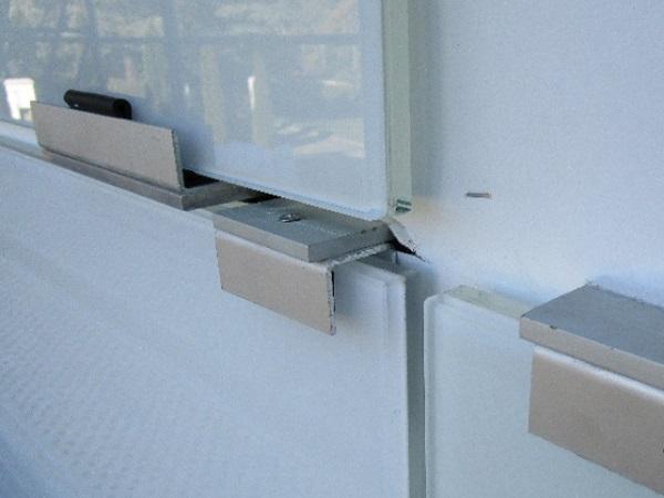
The objective of the mock-up was evaluating the aspect and choosing confirmation the choice of the glass composition. The mock-up fixing clamps were simplified but it was important to keep the real thicknesses of insulations and the real colors of sub-structures. A white film was fixed against the insulation for reducing the sub-structure effect and also to assess different joint solutions.
The client had the chance to evaluate the mock-ups and to understand most of the different constrains and aspects (suppliers, delays, costs, risks and aesthetics) for each one of them. The base project glass composition was the best solution from the technical point of view but the client liked the aesthetics of the other one due to the white PVB which provided a whiter color.
A third mock-up was fabricated for confirming the feasibility of the triple laminated glass with a transparent area. Up to date the glass supplier had just evocated the possibility of trying to produce a glass like that but he had not made a test. This third mock-up was installed beside the first ones and the client decided to push to use this glass composition.
All glasses, supports, frames, sub-structures, fixings, frames, etc. were reengineered and new drawings were produced for the new glass composition. The final glass composition was a triple laminated glass with 8mm thickness each pane.
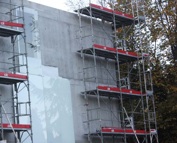
8.Façade installation
Façade cladding installation started in November 2017 with the setting out of brackets and in December 2017 the sub-structure, the insulation and the white back film had already bee installed.
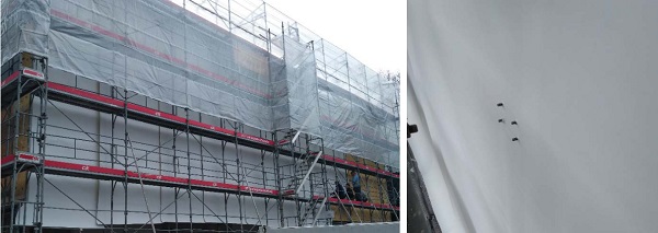
Glass production has also kicked off and the structural silicone bonding has been applied in the workshop under specific conditions.
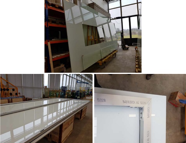
9.Conclusions
Façade glass cladding installation is scheduled in the beginning of April and unfortunately the final project pictures are still not available. Up to date all works have been executed as expected and even when the final conclusions should be written at the end of the project it is already possible to highlight some key points in the façade concept development: the importance of the communication with the client understanding and setting up his preferences; the necessity of research for evaluating all possible material options; and the possibility of developing custom materials and solutions to accomplish all project requirements.
Acknowledgements
Thanks to all BIFF SA team for participating in this project from the first building physics calculations to the final contribution to the execution.