Source:
Challenging Glass 7
Conference on Architectural and Structural Applications of Glass
Belis, Bos & Louter (Eds.), Ghent University, September 2020.
Copyright © with the authors. All rights reserved.
ISBN 978-94-6366-296-3, https://doi.org/10.7480/cgc.7.4479
Authors:
Marcin Kozłowski - Silesian University of Technology
Kent Persson - Lund University, Faculty of Engineering, Department of Structural Mechanics
Dániel Honfi - RISE Research Institutes of Sweden
Natalie Williams Portal - RISE Research Institutes of Sweden

1.General
During the last decades,an increase in structural applications of glass in modern architecture has been observed. This particularly applies to the building components that,in addition to serving as infill elements for openings in buildings, have a special role in ensuring the safety of building occupants.
The main purpose of using barriers in buildings is to protect their users against falling from heights. Barrier elements are usually installed in places where there is a difference in levels between both sides of the barrier (Pinto and Reis 2016). To fulfil safety measures, barriers must meet the requirements regarding minimum height (calculated from the finished floor level to the top edge), load capacity for the strength design (statically and dynamically), and minimum stiffness to limit excessive deflections that may disturb its functionality or building occupants.
Barriers should fulfil their function under ordinary circumstances but also in exceptional cases, e.g. when one glass sheet of the laminate is fractured (Pinto and Reis 2016). Since glass components are susceptible to sudden and brittle fracture, it is important to consider other limit states in addition to the ultimate limit state (ULS) ensuring safety and the serviceability limit state (SLS) focusing on aesthetics and comfort.
These novel limit states (fracture and post-fracture limit states) relate to the situation in which, e.g.one sheet in the laminated glass is damaged,to ensure sufficient damage tolerance and robustness (Honfi et al. 2014, Lenk and Honfi 2016, CEN 2019). In this case, the fractured element should meet the safety function,however, with reduced load. This limit state will be included in the new Eurocode on structural glass (Feldmann and Di Biase 2018).
To guarantee that barriers meet the code requirements, especially regarding impact loads, experiments are often performed. Such tests are costly and time-consuming and are usually limited to a single design case with fixed geometry, thus neglecting the influence of size effect and temperature on the stiffness of the components (Kozłowski 2019a). Finite Element (FE) simulations are an alternative and complementary method to experimental testing.
Despite the good correlation to the results from experiments reported bye.g. Kozłowski (2019a), full nonlinear transient FE models of impact on glassare time consuming and usually require access to advanced commercial FE software and extensive knowledge of users. In the design process, however, time efficient reduction methods allow for a quick check of alternative designs (Fröling et al. 2013, Fröling et al. 2014).
The paper presents an overview of the work completed within the on-going research project “Structural safety of glass components” carried out at the Silesian University of Technology, Lund University and RISE Research Institutes of Sweden. The work involved testing of glass panels having different functions and mounted using different fixing methods, such as linear clamps, local clamp fixings and bolted point fixings through holes in glass. The theoretical basis of a reduced numerical model for the prediction of glass strength under soft body impact is also presented.
2.Classification of Glass Barriers
The most common classification of glass barriers was originally included in the German regulations (TRAV2003) and later adapted in the German standard (DIN 18008-4). The classification of glass barriers protecting against falling depends on geometric features, fixing method and load-transferring function (primary structural element or secondary, non-structural infill). Three main classes of glass barriers are defined: Class A -full height protective barriers, Class B -free-standing glass safety barriers and Class C -barriers with glass infill panels. The correct classification of a barrier is a key element required for structural design and which governs the value of impact loading.
Full height protection barriers (Class A) are vertical glazings fastened linearly or locally, without a handrail to take the horizontal load. Such barriers can take on different shapes and usually consist of full glazing (from floor to ceiling). However, if a handrail carrying horizontal load is mounted in front of the barrier, such an element is classified as Class C (DIN 18008-4).
Free-standing glass barriers (Class B) are panels mounted to the superstructure linearly or locally along its bottom edge. In the case of these barriers, glass is the only structural element carrying the load providing safety for the building users. A handrail along the top edge transfers loads to adjacent panels in the event of glass breakage. Glass filled barriers (Class C) involve a frame carrying the horizontal loads. In this type of protective barrier, glass is only an infill element and does not contribute to the stiffness of the main frame.
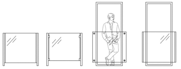
There are barriers with glass infills that do not fit into any of the classes described above, see Fig. 1. In such solutions, glass elements are mounted between steel posts, which may seemingly indicate Class C. However, these panels can be defined as primary structural elements carrying horizontal loads and should therefore be classified as Class A.
3.Impact loads produced by humans in motion
According to the principles of classical mechanics, the kinetic energy of a moving body is a function of its speed and mass (Nilsson 1976). However, during an impact of a human body to an obstacle, only 30-60% of its mass takes part in the event and the reduction of mass is caused by the fact that the human body is not perfectly rigid but it is a complex dynamic system and some energy remains diffused during the impact (Nilsson 1982).
Nilsson (1982) conducted research to assess impact forces associated with various types of human activities. The researcher employed volunteers leaning on and kicking a glass pane with the dimensions of 1000×2000 mm2 with a 10 mm thickness. The glass pane was equipped with a load cell measuring the applied impact force. The main aim of the research was to define factors to approximate the dynamic force based on the static mass of a human. For kicking, leaning and pushing a person ona glass pane, the dynamic amplification factor achieved was 1.5, 3.9 and 4.1, accordingly.
Huber (1995) carried out experiments with volunteers who shouldered a glass pane measuring 875 × 1938 mm2 with a 10 mm thickness. The specimen was supported along all edges and equipped with a load cell. A maximum dynamic force of 2.2 kN was obtained.
Wörner and Schneider (2000) conducted human body impact tests using volunteers with the following weights 68, 83 and 90 kg. In the first stage, the volunteers ran from a defined distance of 2.5 m and hit a glass pane that measured 847 × 1910 mm2 with a 10 mm thickness. The pane was supported along all edges. In the next stage, the same pane was hit with a 45 kg impactor from drop heights: 450, 700 and 1200 mm.
During the experiments, the strain in the glass was measured with gauges mounted on the tensile stress side of the glass. The researchers observed that the micro strain in the glass was much lower as a result of human impact compared to the pendulum impact. The maximum measured strain in the glass, recorded under human impact with a mass of 90 kg, was approximately 60% lower than the strain obtained when the pendulum was dropped from the highest drop height of 1200 mm.
It was also observed that the contact time measured during tests with volunteers in relation to the pendulum impact was longer by approximately 50% and lasted in average 80 ms. This result is due to the lower rigidity of the human body as compared to the stiffness of the pendulum. Additional results research are presented in Schneider (2001).
Ummenhofer (2004) conducted research with volunteers running and hitting a wooden board with the dimensions 500 × 500 mm2 and 12 mm in thickness. A load cell was attached to the board measuring the response during impact. An average force obtained in the experiments was 1.66 kN.
Bucak (2004) carried out a study in which a volunteer, weighing 82 kg, was skateboarding and shouldering a glass pane. The glass pane, supported along its short edges, measured 360 × 1100 mm2 with a 8 mm thickness. Before each impact, the speed of the skateboard and the deflection of the pane were measured. The results of the tests were compared with results from a numerical model of a glass pane. The numerical results were based on a 50 kg pendulum load moving at the same velocity as the maximum speed of the skateboard measured during the tests. It was found that the results from the numerical model were approximately 50% greater than that observed during the experiments with the volunteer. Additional results are presented in Schuler et al. (2005).
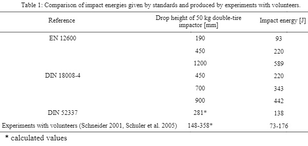
Table 1 presents a comparison of impact energies given by standards and produced by experiments with volunteers. The impact energy calculated with the method in DIN 52337 was calculated based on the assumptions that an 80 kg human is moving at a velocity of 2.4 m/s (maximum speed of a human inside buildings) and that 80% of its mass is actively involved in the impact event. For comparison, Table 1 provides corresponding drop heights of a 50 kg double-tire impactor calculated from the impact energies achieved during the experiments with volunteers. The values were calculated using the formula for the potential energy Ep= m×g×h, where m is the impactor mass, g is the acceleration of gravity (9.81 m/s2) and h is the drop height (in meters).
4.Overview of Experimental Campaign
An extensive experimental campaign was carried out in this research project. The testing program involved both the static and dynamic characterization of a double-tire impactor, as well as impact testing of glass panels mounted using various fixing methods. The fixing methods included linear clamping, bolted point fixings through holes in glass and local clamp fixings without penetration of glass. The investigation was made by varying glass thickness, types of glass and interlayer stiffness.
4.1.Static and dynamic characterization of a double-tire impactor
In the project, a double-tire impactor according to EN 12600 was used. The 50 kg impactor consists of two pneumatic tires, inflated to 3.5 bar air pressure, and a central steel cylinder. To define the parameters of the hyper elastic material model assumed for the rubber in the tire, a tensile test of a strip cut from the tire was tested in tension. In addition, static compression of the inflated impactor was performed to obtain stiffness features under static loads. Details of the set-up and results can be found in (Kozłowski 2019a, Kozłowski 2019b).
Dynamic characterization of the impactor was performed by setting the impactor into pendulum motion from different drop heights and hitting an obstacle of very high stiffness. By regarding the obstacle as rigid, it was possible to determine the dynamic characteristics of the impactor. In the study, five drop heights were investigated: 100, 200, 300, 450 and 700 mm resulting in impact energies ranging from 49.1 to 343.4 J. To measure the acceleration and contact time of the pendulum during impact, a single-axis accelerometer was mounted to the steel cylinder above the top tire. Acceleration measurements were carried out with data acquisition of 5 kHz.
4.2.Soft body impact tests
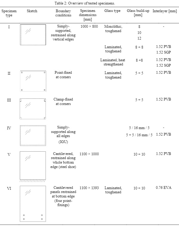
An overview of the specimens tested in the soft-body impact tests is presented in Table 2. The specimen type and the boundary conditions employed in the study represent the most prevalent fixing techniques applied in buildings. The glass specimens in this study were regular soda-lime silicate float glass, which is the most common glass type in the building industry. Two types of heat treated glass were applied: heat-strengthened (HS) and fully tempered (FT) glass. Three types of interlayers were applied: regular polyvinyl butyral (PVB), ethylene vinyl acetate (EVA) and SentryGlas® (SG).
The research project included the following elements:
• Glass panels supported along their vertical edges. Panels with dimensions of 1000 × 800 mm2 supported linearly along their vertical edges were investigated. Three monolithic panels of various thickness: 8, 10 and 12 mm made of toughened glass were tested to obtain data to calibrate numerical models. Moreover, two laminated glass panels (8+8 mm) made of toughened and heat-strengthened glass with two interlayer materials: PVB and SG 1.52 mm in thickness were investigated.
• Point and clamp fixed panels. These types of elements are usually installed as infill panels for steel balustrades. Panels measuring 1000 × 800 mm2 supported locally (with point fixings and clamps) at points located approximately 50mm from the corners were investigated. A single laminated panel composed of two 5 mm toughened glass panes laminated with a 1.52 mm PVB interlayer was investigated.
• Insulated glass units. Two specimens with symmetric and asymmetric configuration were investigated. The first specimen consisted of two single 5 mm panes, while the second specimen had a laminated ply with 5+5 mm glass,and a 1.52 mm thick PVB layer on one side. In both cases, the gas-filled cavity was 16 mm in width and the glass was fully toughened. The panels were simply supported along all edges.
• Free-standing glass balustrades (Biolzi et al. 2018, Baidjoe et al. 2018). These are cantilevered elements supported at the bottom edge only. In the research project, both line and point fixed configurations were tested in both static and dynamic loading. Laminated glass panels were composed of two 10 mm plies made of toughened glass laminated witha1.52 mm thick PVB interlayer for the line fixed configuration and a 0.76 mm EVA interlayer for the point fixed configuration.
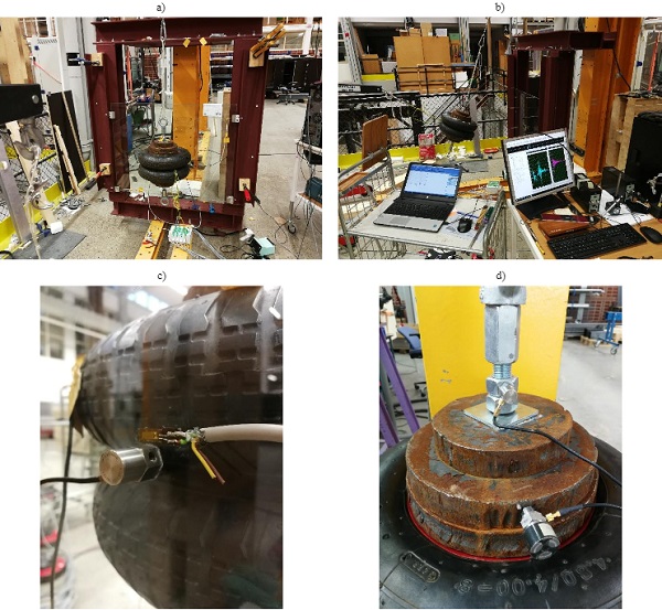
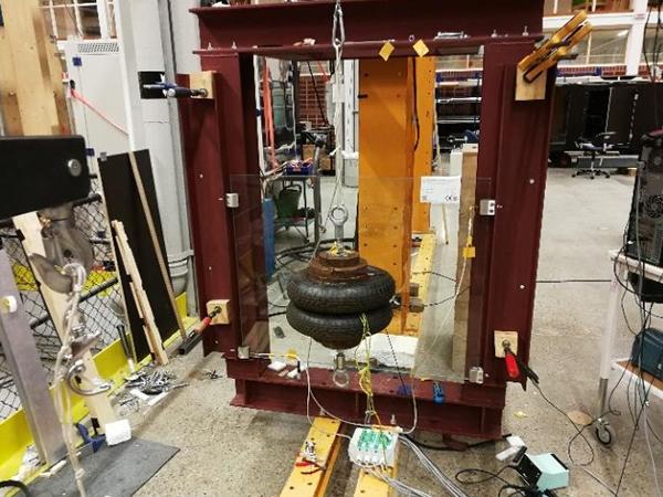
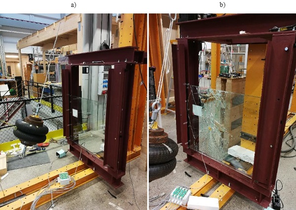
Specimens I-V were tested in a custom-made steel frame of high stiffness (Fig. 2a). The set-up allowed for fixing the various specimens and releasing the impactor from defined drop heights. To measure the structural response of the glass elements during soft-body impact, two systems with a number of sensors were installed (Fig. 2b). To measure strains in glass, strain gauges with a measurement length of 10 mm and a single axis accelerometer were bonded to the specimens (Fig. 2c).
The signals from the strain gauges were logged at a frequency of 600 Hz, where as the readings from the accelerometers were recorded at 5 kHz. A single-axis accelerometer was also mounted to the impactor (Fig.2d). To obtain statistically reliable results, at least six repetitions for each drop height were performed. All tests were carried out at a temperature of 22±1 °C.
The specimens were tested in both an intact (Fig 3a) and a damaged state (Fig 3b) to investigate the behaviour of specimens, where one of the plies were intentionally fractured. To brake one of the panes in the laminate, a hammer and a steel chisel were used. Due to the energy stored in the heat-treated glass (introduced to the glass in a tempering process), the damaged ply increased its volume and some of the strain gauges bonded to the cracked glass were damaged.
Specimen VI was tested at another laboratory and in a different set-up, as described in Williams Portalet al. (2019). Static and impact tests were conducted on a self-supporting glass balustrade with point-fixings. The specimen was subjected to both static and impact loading (with various drop heights).
The dynamic structural response of the glass specimen was analysed by three-dimensional Digital Image Correlation (3D-DIC) measurements using a stereoscopic camera setup with two high-speed cameras. This measurement technique makes it possible to determine the strain and deformation of any point on the specimen surface and to study its deformed shape in detail.
5.Full Transient and Reduced Numerical modelling
5.1.Full modelling
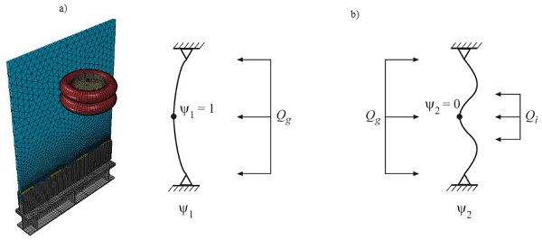
Numerical models were created to reproduce the structural behaviour found on the specimens subjected to the soft-body impact. Models were created using the commercial finite element analysis (FEA) software ABAQUS and were analysed using the Implicit Dynamic solver (Simulia 2018). An example of a numerical model of a free-standing glass balustrade and the impactor is shown in Fig. 4a.
The model of the impactor followed that of EN-12600 and consisted of two tires and a steel weight (Fig. 4a). The model of a single pneumatic tire was created by revolving a curve corresponding to the mid cross-section of the tire and the steel rim around its perimeter. To achieve a realistic behaviour of the tire, the reinforcement (nylon cords) was included and modelled by using a smeared approach in membrane elements. The displacements of the shell and the membrane elements were fully coupled. In this way, high tensile but low bending stiffness of the tire was achieved.
The air inside the tires was modelled using pneumatic elements in the closed cavity. This required the definition of a closed volume between the inner surface of the tires and the outer surface of the rim, the volume of the cavity being controlled by a cavity reference point. In such a case, the stiffness of the tire depends not only on the rubber material and the initial pressure exerted by the gas entrapped inside but also on the volume change of the cavity that is affected by the external loading and deformation of the tire.
To achieve equilibrium with the initial pressure of 3.5 bar, as required to conform with EN 12600, an overpressure of 4.25 bar was applied which after equilibrium iterations and tire deformations, settled at 3.5 bar. Laminated glass elements, including the glass panes and the interlayer, were modelled using eight-node continuum shell finite elements. Details of the tire model and the material properties can be found in Kozłowski (2019a).
Laminated glass elements, including the glass panes and the interlayer, were modelled using six-node continuum shell finite elements. Other elements of the model, such as steel elements of the test set-up, setting blocks and other glass fixing elements were modelled using solid elements. A non-regular, triangular mesh pattern was applied for the laminated glass components.
A finer mesh with an element size of 5 mm was used for the lower part of the panel where the highest stresses were expected, while the remaining zones were meshed with a coarser pattern with an average element size of 30 mm. For other components of the model, such as the steel plates and fastening elements made of polyoxymethylene (POM), a10 mm element size was applied. Details of the numerical model and material properties can be found in Kozłowski (2019a).
5.2.Reduced Modelling
Full nonlinear transient finite element analyses of impact events are advanced, time consuming and may require access to advanced commercial finite element programs and trained users. In the design process, it is important that the design tools used are such that alternative designs may be tested in an interactive fashion. To achieve this, there is a need to have methods that are very time efficient.
A solution may be to employ Model Order Reduction (MOR) methods for the FE-models. This means reducing the initial large number of degrees of freedom with the aim of keeping the dynamics of the original model as intact as possible. In many cases, only a very few degrees of freedom (dofs) are sufficient to provide a good solution, in many cases even only one dof can be sufficient.
In an ongoing study on model reduction of glass impact, the aim is to, in an efficient and simplified manner, be able to determine the maximum principal stress of a glass plate subjected to a dynamic impact load. The method must be valid for glass supported by various types of fixings and with different sizes and laminations. In Fröling et al. (2014) a reduction method for impact on glass based on Ritz vectors was suggested.
The method includes two Ritz vectors, calculated from two static load cases representing the glass structure, as well as a spring, dashpot and mass representing the impactor. The load cases are schematically shown in Fig.4b. Although this method has been shown to provide very good results for many glass types, dimensions and supports, it is not fully general. Since the method is based on two Ritz vectors determined from static load cases, the validity of the solution is dependent on that these load cases are valid.
A vast number of methods for model order reduction of dynamic problems have been developed within structural mechanics where various mode-based methods are the most frequently used methods. Fairly recently, methods originating from control theory have been employed within structural mechanics. In contrast to mode-based methods which have an explicit physical interpretation, the modern reduction methods are developed from a purely mathematical point of view.
An FE formulation of a structural dynamics problem results in a linear equation of motion of the following form
![]()
where M, Cand Kare the mass, damping and stiffness matrices respectively, F=F(t) is the load vector and u=u(t) is the displacement vector with n number of dofs. A dot denotes differentiation with respect to time, t. The objective of model reduction here is to find a system of m number of dofs in which m << n, one of which preserves the dynamic characteristics of the full model. The general approach is to approximate the state vector using transformation.
u = TuR, where T is a transformation matrix of size (m x n) and uR is a reduced state vector of size (m x 1). Applying the transformation in question to Eq. (1) results in
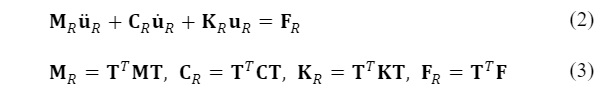
where MR, CR, KR are the reduced mass, damping and stiffness matrices, respectively of size (m x m).
The reduction methods can be categorised according to the type of dofs generated in the reduction process, where condensation methods involve only physical dofs, generalised coordinate methods are based solely on generalised coordinates, and hybrid reduction methods employ a combination of dofs of both types. A number of important methods within each category described further by Flodén et al. (2014) are listed below:
• Condensation methods: Guyan reduction, Dynamic reduction, Improved reduction system and System equivalent expansion reduction process
• Generalized coordinate methods: Modal truncation, Component mode synthesis by Craig–Chang, Krylov subspace methods and Balanced truncation
• Hybrid methods: Component mode synthesis by Craig–Bampton, Component mode synthesis by MacNeal and Component mode synthesis by Rubin
In the current work on finding a suitable reduction scheme for soft body impact on glass, these methods were studied together with updated methods based on Ritz vectors.
6.Results and Discussion
The section presents selected results from experimental tests. It includes results from the dynamic characterization of the impactor and results from the soft-body impact testing of glass panels.
6.1.Dynamic characterization of double-tire impactor
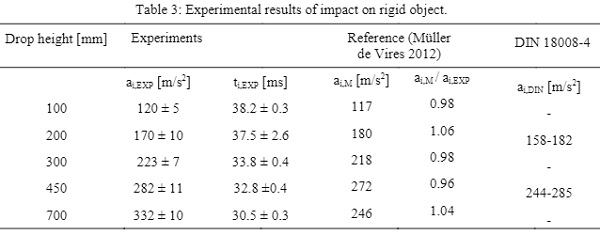
In Fig. 5a, the experimental set-up of impact on an obstacle of high stiffness (steel column) is shown and in Fig. 5b the results in terms of a time history of the impactor’s acceleration are presented. Table 3 shows obtained maximum values of acceleration (ai,EXP) and impact time (ti,EXP), which relate to the time of contact between the tires and the rigid body. As a reference, the results obtained by Müller de Vries (2012) and DIN 18008-4 are presented.
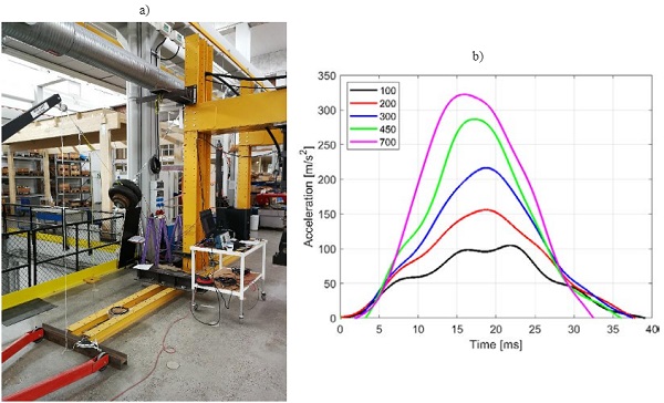
The experimental results obtained in the study have a good correlation with the reference values. The 6% difference was likely caused by the differences in the test set-ups. In the reference studies (Müller de Vries 2012), the impactor hit a reinforced concrete wall with a presumably higher stiffness than the steel column used in the current study.
In addition, in the reference tests, the pendulum was inflated to a pressure of 4.0 bar, while in these tests, the air pressure was 3.5 bar, which is in accordance with EN 12600. In Table 3, the reference range of the impactor’s acceleration (provided by DIN 18008-4) tested against a rigid wall for the drop heights of 200 and 450 mm are also presented. The experimental results obtained in this study fit within this range.
6.2.Soft body impact tests
This part of the paper presents selected results of the impact tests carried out within the research project. The stress in the glass was calculated based on the measured strain and a value of Young’s modulus of 70 GPa. For the specimen type I, the results show stress values in the glass based on the measurements from strain gauges mounted on the backside of the panel (the surface of the pane that is on the opposite side to the pendulum). Regarding specimen type V, a pair of gauges were mounted on opposing sides to measure both tension and compression stresses (Kozłowski 2019a).
6.2.1. Specimen type I – monolithic and laminated panels
Fig. 6a presents histories of horizontal stress in glass under soft-body impact for drop heights: 300 and 500 mm, which correspond to the impact energy of 147.1 and 245.2 J, respectively. The results are shown for the specimen type I – monolithic panels, simply-supported along vertical edges, with different thickness: 8, 10 and 12 mm. The panels were made of toughened glass. Thinner glass panes show higher stress under impact than thicker panes.
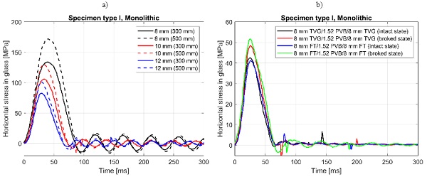
Fig. 6b presents horizontal stress histories in the glass under soft-body impact for laminated specimens type I. The laminate in this glass consisted of two plies of 8 mm in thickness bonded with a 1.52 mm PVB interlayer made of one toughened and one heat-strengthened glass. In the tests, the impactor was released from a 300 mm drop height.
Two states of the laminated elements were considered: the intact state and a broken state in which one of the plies (located on the pendulum side) of the laminate was fractured. It is a well-known observation that fully toughened and heat-strengthened glass fracture in different manner. This phenomen on results in different stiffnesses of laminated elements (with single ply fractures) and thus the stress in glass depends on which type of glass is broken.
6.2.2. Specimen type V – free-standing glass balustrade
During the experiments with the glass balustrade in the intact state, special attention was paid to its detailed global behaviour during impact. Four characteristic phases were identified. In the first phase, the pendulum hit the glass balustrade and showed significant deformations. Subsequently, in the second phase, the balustrade experienced elastic deformations and in the third phase, the balustrade sprung back towards its initial position to hit the pendulum a second time. Then, the impactor started moving in the opposite direction away from the balustrade. This phenomenon can be also noticed in the stress history (Fig. 7b) in which the stresses in glass, after reaching the maximum value, does not decrease smoothly and a second smaller peak can be noticed.
The balustrade shows a different behaviour when one pane is fractured, as shown in (Fig. 7a). It depends primarily on which side the fractured ply is located (in relation to the impactor). By comparing the stresses measured during the impact (Fig. 7c and 7d), it can be concluded that the influence of the fractured pane on the compression side contributes to the global stiffness of the element; whereas, the fractured pane on the tensile side is negligible, given that the effect of the added mass is neglected.
7.Numerical modelling
This section presents selected results from numerical simulations of soft-body impact testing related to the specimen type V – free standing glass balustrade.
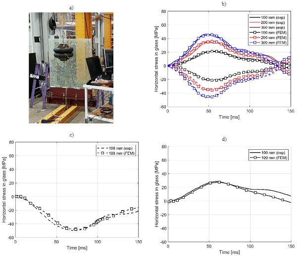
In the intact state, a good correlation of experimental and numerical results can be observed for the stress history, see Fig.7b. This applies especially for the time duration before the first contact of the impactor with the glass pane. At 100 ms, when approximately the second impact occurs, the numerical model slightly underestimates the stress values measured in the experiments.
This is probably due to the fact that the PVB interlayer has a viscoelastic behaviour that is rate dependent and since the strain rates differ between the first and second impact.Thus, a lower stiffness during the second impact is observed in the experiments. This is a phenomenon not included in the FE model. The second impact in the simulations takes place approximately 10 ms earlier than in the tests, which indicates a higher stiffness of the balustrade as compared to the experiments and thus confirms the above observations. In the intact state, the numerical results over estimate the experiments by less than 10%.
Fig. 7c and 7d show comparisons of the experimental and numerical results for the specimen in a fractured state with the broken panel located on the impactor side and on the opposite side, respectively. As in intact state, a good agreement was obtained in the first stage of the impact (up to approximately 100 ms). In terms of maximum stress in the glass, the numerical model underestimate the experiments by less than 5%.
8.Conclusions
With the increasing use of glass in buildings as a result of new technical solutions and updated requirements, better methods are needed for the safety verification of glass balustrades. A combination of testing and numerical modelling is useful in gaining a better understanding of the structural behaviour of such assemblies, especially with regard to impact loading.The studies performed in the current project lead to the following major conclusions:
• Experiments with volunteers show much lower values of impact energy than given by the standards (DIN 18008-4, DIN 52337). Maximum energy obtained in the experiments with volunteers corresponds to the drop height of approximately 360 mm with a double-tire impactor with the mass of 50 kg. The maximum drop height provided by DIN 18008–4 is 900 mm, which provides a safety factor of 2.5.
• It is possible to predict the structural behaviour of free-standing glass balustrades subjected to soft-body impact using full transient non-linear numerical models, however, these are time consuming and require access to advanced commercial FE software and extensive user knowledge.
• There is a strong need for reduced modelling techniques that are time efficient and allow for a quick check of alternative designs.
9.Acknowledgements
This presented work was financed within the research project “Structural safety of glass components” (grant number 18-510) financed by the ÅForsk Foundation.
10.References
Baidjoe, Y., Van Lancker, B.,Belis, J. Calculation methods of glass parapets in aluminium clamping profiles. Glass Struct.Eng.3, 321–334 (2018)
Biolzi,L., Bonati, A., Cattaneo, S.:Laminated Glass Cantilevered Plates under Static and Impact Loading.Adv.Civ.Eng.vol. 2018, Article ID 7874618, 11 pages, (2018)
Bucak Ö.: Bauteilversuchezur Ermittlung der Schultersteifigkeit beim Anprall an Glas, Forschungsbericht, Fachhochschule München (2004)
Feldmann,M., Di Biase, P.: The CEN-TS Structuralal Glass –Design and Construction Rules as pre-standard for the Eurocode Proceedings of Engineering Transparency, Duesseldorf pp. 90-98(2018)
Flodén, O., Persson, K., Sandberg, G.:Reduction methods for the dynamic analysis of substructure models of lightweight building structures. Comput.Struct.138, 46-61(2014)
Fröling,M., Persson,K., Austrell,P.E.: A reduced model for glass structures subjected to dynamic impact loads. Proceedings of COST Action TU0905 Mid-Term Conference on Structural Glass, 9-13 (2013)
Fröling,M., Persson,K., Austrell,P.E.: A reduced model for the design of glass structures subjected to dynamic impulse load. Eng. Struct. 80, 53-60 (2014)
Huber,K.: Entwicklung eines Stoßkörpers für Pendelschlagversuche, 34867, IFT Rosenheim Institut für Fenstertechnik Fenstertage (1995)
Kozłowski, M.: Glass balustrades. Experimental and numerical analyses, basis of design, Silesian University of Technology Publishing, Gliwice (2019a), ISBN 978-83-7880-618-9
Kozłowski, M.: Experimental and numerical assessment of structural behaviour of glass balustrade subjected to soft body impact.Comput. Struct. 229,111380 (2019b).doi: 10.1016/j.compstruct.2019.111380
Müller de Vires, C.: Numerical simulation of facade/window glazing fracture under impact loading. In: Proceedings of Challenging Glass 3-Conference on Architectural and Structural Applications of Glass, Delft (2012)
Nilsson,L.: Impact Loads Produced by Human Motion, Part 1: Background and experimental investigation, Lund University, Lund (1976)
Nilsson,L.: Impact loads produced by human motion, LundUniversity, Lund (1982)
Pinto,A., Reis,L.: Barrier for buildings: analysis of mechanical resistance requirements.Proc. Struct. Integr. 1, 281–288 (2016)
Siebert,B.: Glass balustrades and French balconies –Design and testing. In: Proceedings of Challenging Glass 4 & COST Action TU0905 Final Conference, 463-471, Lausanne (2014)
Simulia ABAQUS v. 6.14; Computer Software and Online Documentation; Dassault Systems: Providence, RI, USA (2018)
Schneider,J.: Impact Loading on Glass Panes by Soft Body Impact –Theoretical Analysis and Experimental Verification. In: Proceedings of Glass Processing Days, 682-687, Tampere (2001)
Schneider,J.:Festigkeit und Bemessung punktgelagerter Gläser und stoßbeanspruchter Gläser, Technische Universität Darmstadt Institut für Statik, Dissertation (2001)
Schuler,C., Koch,S., Binder,M., Bucak,Ö.: Comparative studies to shock loads during the construction project Zoo Wuppertal, University of Applied Sciences Munich (2005), unpublished
Ummenhofer,T.: Auswertung von Anprallszenarien von Menschen auf Kraftmessdosen, Institutsbericht unveröffentlicht, Technischen Universität (2004)
Wörner,J., Schneider,J.: Zwischenbericht zur Durchführung von Versuchen zum weichen Stoß mit dem Pendel nach DIN EN 12600, Institut für Statik, Darmstadt (2000)
Williams Portal,N., Flansbjer,M., Honfi,D.: Testing of self-supporting laminated glass balustrades, RISE Report: 2019:112 (2019).http://ri.diva-portal.org/smash/record.jsf?pid=diva2%3A1372865&dswid=4819
DIN 18008-4 Glass in Building–Design and construction rules -Part 4: Additional requirements for barrier glazing (2013)
EN 12600 Glass in building. Pendulum test. Impact test methodand classifi-cation forflat glass method and classification for flat glass (2002)
TRAV 2003 Technische Regeln für die Verwendung von absturzsichernden Verglasungen (TRAV), Fassung (2003)
prCEN/TS xxxx-1:2019 Design of glass structures —Part 1: Basis of design and materials