Article Information
- Digital Object Identifier (DOI): 10.47982/cgc.8.460
- This article is part of the Challenging Glass Conference Proceedings, Volume 8, 2022, Belis, Bos & Louter (Eds.)
- Published by Challenging Glass, on behalf of the author(s), at Stichting OpenAccess Platforms
- This article is licensed under a Creative Commons Attribution 4.0 International License (CC BY 4.0)
- Copyright © 2022 with the author(s)
Authors:
- Keyan Rahimzadeh - Front, Inc.
- Evan Levelle - Front, Inc.
- John Douglas - Alutec Qatar
Abstract
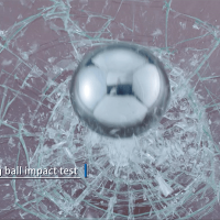
Cold-bent glass is seeing increasing adoption in construction projects with non-planar geometries. This paper presents work undergone for a set of four high-rise towers, featuring 11,136 unique cold-bentpanels, hundreds of which are pushed beyond 250mm. The panels are all unique, non-rectangular, and in some cases, slightly curved. The challenging geometry complicates the prediction of the final panel shape, which is an essential step for producing fabrication drawings of a panel’s flat shape prior to bending.
While Machine Learning is still a nascent technology in the AEC industry, prediction is a class of problems for which many Machine Learning techniques are ideal, especially when dealing with a large quantity of data, or in this case, panels. The paper discusses the geometric characteristics of highly bent glass, a methodology for the shape prediction of the panels, and the use of Machine Learning in its implementation. The methodology was deployed for over 3,500 pieces of installed architectural glass, and was shown to reduce geometric deviations as much as 75%, down to sub-millimetre tolerances.
1. Introduction
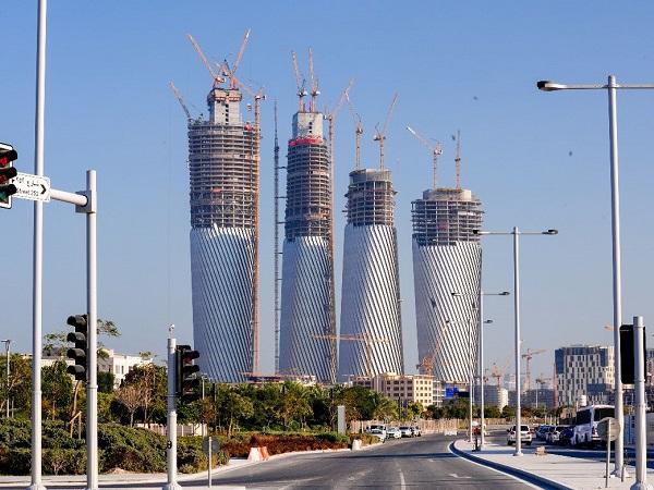
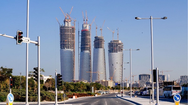
Cold-bending is a technique that enables the use of glass in construction projects that feature organic or otherwise non-planar geometries. As cold-bending methods become more thoroughly understood and deployed, their limitations are being investigated and challenged. In a recent project, four high-rise towers (two at 240 meters height, two at 300 meters) feature 11,136 unique cold bent panels. Of those thousands, several hundred panels are pushed as much as 200 to 400mm out of plane.
Much of the research around cold-bending and its mechanical limitations regard rectangular, or even square panels, but it’s also well established that the shape of the panel has a significant impact on the buckling characteristics. Since rectangles cannot tile a non-planar surface, it is very likely that most cold-bending applications will require panels that are not rectangular. The panels in this project are skewed quadrilaterals and serve as a useful study for the nature of elastic deformation in non-rectangular shapes.
While the interplay of geometry and material is important to understand during design and engineering, it is absolutely essential when preparing for fabrication. For the panels to fit into their frames correctly, one must properly account for the geometric distortions when predicting the final, flattened panel shape. Doing so requires a series of material simulations which are computationally expensive and time consuming, at least at the scale of thousands and thousands of unique instances.
Prediction, however, is a class of problems well suited to Machine Learning algorithms. We therefore created a methodology to define the surface as a set of parameters, which makes it possible to train a Machine Learning model for the prediction of cold bent surface geometries in architectural glass panels.From that final predicted shape, we use Finite Element Analysis to simulate the bending in reverse, and predict the flat, “unrolled” shape, while accounting for material properties and thickness.
Herein, we discuss the idiosyncrasies of highly deformed glazing and the methodology for training and implementing the Machine Learning model.
2. Project Description
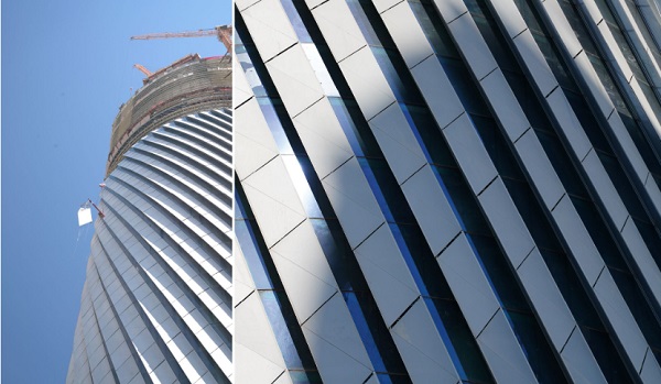
The towers' overall shape is defined by two ellipses, one at the base and one at the top, which have slightly different radii, and are rotated relative to each other by 90 degrees. A custom algorithm defined by the architects determines the freeform surface that interpolates these two guiding curves. That surface provides the basis for subdivision into facade panels.
The facade features a 3-dimensional shading element, and the panelisation follows an incline to increase the effectiveness of the shade. This results in the angled, spiralling effect, and importantly, results in panels that approximate parallelograms. Of course, because the massing is a continuously curving shape, the panels cannot sit flat on the surface, but must bend out of plane.
There are many techniques for deforming glass to conform to non-linear shapes, and the considerations for selecting one technique or another have been discussed widely (Beer 2019, Gopal 2015, Datsiou 2017). Among the advantages of cold-bending is the fact that you do not have to use heat to soften the glass, the deformation is done at room temperature. This reduces time and equipment required. Of course, the technique also comes with limitations, including but not limited to the structural capacity of the glass when bending, and the onset of a unique type of buckling, sometimes referred to as “snap-through” buckling (Bensend 2015, Bensend 2016, Bensend 2018).
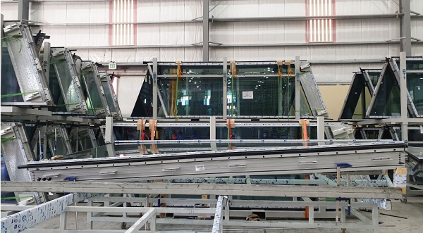
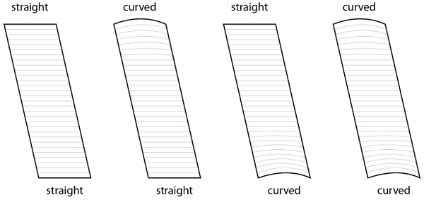
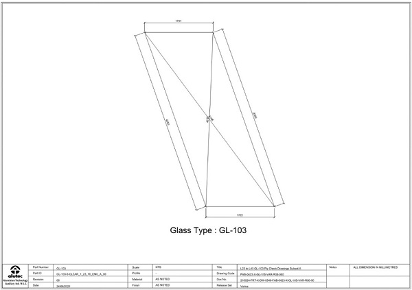
Since the structural slab is following the contours of the façade, there are some locations where the glass panels, if they were to have all-straight edges, a straight line along the top or bottom would encroach on the space between the façade line and the slab. For this reason, some panels have a curved edge at the top, bottom, or both. This leads to four panel types, as shown in Figure 3.
3. Problem Definition
Stated most simply, the challenge is to correctly predict the final 3-dimensional shape of the glasssurface. If predicted correctly, then a material simulation can be used to "flatten" the 3D shape into the correct 2D outline, so that it may be fabricated from flat stock materials.
Below are explanations of the many facets of the problem.
3.1. Geometry of Cold-Bent Glazing
In small degrees of cold-bending, the amount of distortion in the shape is small, and therefore the flat 2D shape can be derived from a 3D wireframe of the edges in a straightforward way, such as measuring the edge lengths and internal angles, then re-drawing the panel in 2D. However, as the surface undergoes significant deformation, such methods lose accuracy, which will be discussed in more detail below.
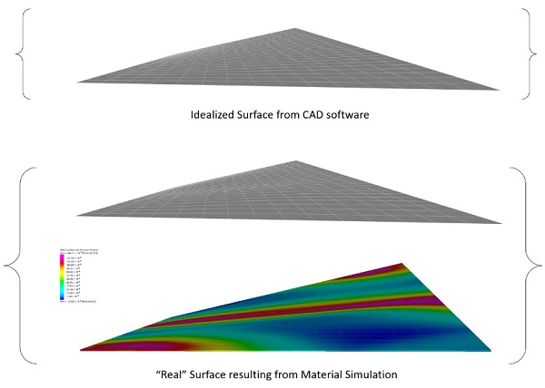
This surface also cannot be simply generated using then native surfacing algorithms in a given CAD software, such as NURBS or other geometric frameworks. For example, lofting or creating a 4-sided NURBS surface from the boundary curves will produce a surface that is informed by the mathematical formulations of Bezier splines, not the physical-mechanical behaviour of glass.
There have been advances in the interactive prediction of 3-dimension glass surfaces directly in the modelling environment (Gavriil, et. Al 2020), however those methods focus on monolithic thin-glass applications and do not encompass the question at hand here, namely, how to predict the flat fabricated shape that will, when deformed, match the 3D frame.
The most common application of cold-bending assumes a flat rectangle, with one corner raised out of plane. In purely geometric terms, this is well known as a “hypar”, short for hyperbolic paraboloid, a shape that famously features straight ruling lines but also anti-clastic double curvature. While such geometry is double-ruled, and therefore can be realized with linear elements, it is not-developable, i.e., it cannot be created from physical sheet materials without stretching or distortion.
At low levels of cold bending, the degree of curvature is minor, so the rigid glass panel can approximate the shape within tight levels of tolerance. As the double curvature increases, the theoretical anticlastic shape and the true shape that a rigid material would form, diverge further and further, eventually becoming significant enough to be relevant to matters of construction.
Depending on the motivations of the designers and engineers, this may or may not be a problem. If the designer intends to maintain strict control over the surface curvature of the glass (and therefore the visual qualities of reflections), then cold bending is not likely to be a suitable strategy. The decision whether to pursue cold bending requires a nuanced conversation among the design team about the expectations of visual distortions (Gopal 2015).
3.2. Panel Distortion and Edge Conformance
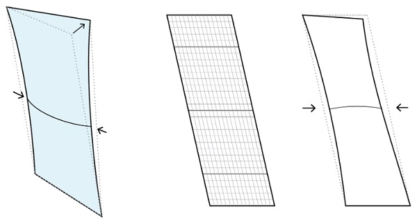
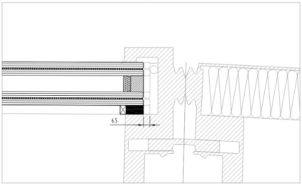
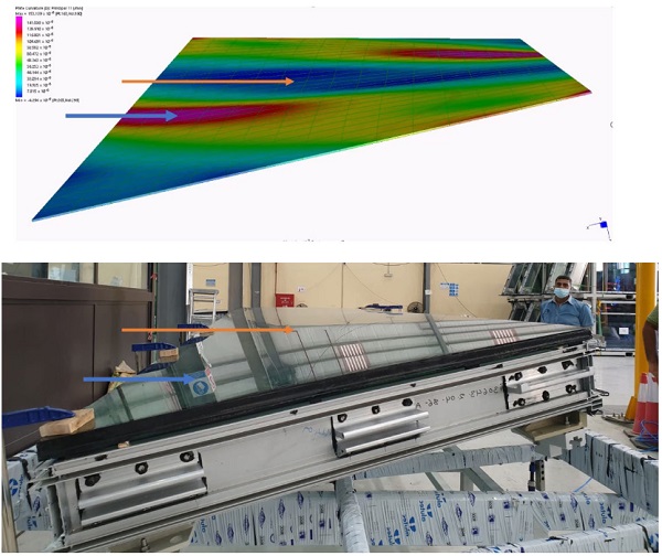
However, even if the design team agrees that visual distortions do not need to be managed, this geometric deviation still presents technical challenges. One of these issues is the linearity of the framing, as compared to the potentially non-linear edge of the deformed glass panel.
As illustrated below, as the panel develops curvature in its central area, the edges do not maintain linearity. The narrowing effect is small relative to the size of the panel, ranging from negligible to as much as 6.5mm. While this may seem minor, 6.5mm is enough to significantly compromise the structural silicone bite, or the viability of mechanical restraint systems.
3.3. Engineering and Fabrication Considerations
Cold bending is still a relatively new approach to facade design, and there are many factors to consider when engineering the system. There are also many different solutions and techniques that can be used. The reader is referred to the literature for a more complete review of these topics (Beer 2019, Nardini 2018).
For the purposes of providing context for the rest of this paper, the most relevant decisions made throughout the design process are as follows:
- Frames will be built in their final 3D shape prior to glazing. Therefore, the stiffness of the frame itself contributes to maintaining the shape and reducing long term stress on the structural silicone bite.
- The IGU is comprised of two laminated lites, which have been formed into their final 3D shape in a process sometimes called "lamination bending", or "cold bent lamination"
- The individual plies of glass are laid up, as a glass-interlayer-glass sandwich, which is then held in its warped shape within a rigid frame, or jig. At that point, it is placed into the autoclave.
- As the interlayer sets, the stiffness of the interlayer works to hold the two plies of glass in the desired 3-dimensional shape.
Because the individual plies are warped into shape before the interlayer has been bonded to the glass,there is no shear transfer between plies prior to lamination. The task at hand was to be able to approximate the distorted surface geometry of the panel closely enough to predict the flattened shape; it was assumed at this stage that the two plies of the laminate would have the same deformed shape (since they are the same flat shape, pushed to the same depth), and therefore could be simulated as independent plies, at least for the purposes of determining the fabrication geometry. Whether the interaction of two stacked plates with physical contact but no shear interaction influences the final cold-bent shape prior to lamination (or after, for that matter) is a question that merits further investigation.
3.4. Unique Panel Shapes
Because the overall form is bi -axially symmetric, one may presume that the facade would feature some degree of repetition, especially since this may provide manufacturing advantages. However, while the surface itself may feature symmetry, the facade panelisations follows a single direction of inclination, which significantly complicates matters of repetition. Further, because ellipses have a continuously variable curvature, each panel is different from the one adjacent to it, so there would only be, at best, 4 copies of a given panel – one in each quadrant of the ellipse.
For these reasons, among others, the project was conceived early on to employ principles of Design For Manufacture and Assembly (DFMA). That is, the pre-existing assumption that panels would be fabricated using CNC and automated processes. Since there would only be, at best, 4 copies of a given panel, the overhead required to keep track of types and repetitions was more cumbersome than developing a management system that was defined by an assumption of 100% bespoke panels.
3.5. Machine Learning as a Technique
Machine Learning is a broad field of study, primarily in the field of computer science. There is a huge body of writing and research on this topic; for the purposes of this paper, we provide a very simple description of its principles, as relates to the studies. In short, “Machine Learning” (ML) refers to a subset of algorithms and techniques in the broader field of “Artificial Intelligence” (AI). In essence, the algorithm receives a “sample”, which is an instance of input values and output values.
The algorithm will aim to create a “map” from the inputs to the outputs. As the sample size grows, meaning more instances correlating inputs to outputs, the accuracy of the “mapping” improves. This mapping is called a “model”, and the process of providing example samples is called “training”. Eventually, when the model has been trained to a sufficient level of accuracy, then new input values can be provided, and the algorithm will then return predicted output values.
There is significant detail and nuance to this process, and a huge variety to the algorithms and systems that can be used; those who are familiar with Machine Learning may find this explanation an oversimplification, but for those who are new, hopefully this serves as a sufficient framework for understanding the rest of the discussion.
Machine Learning is very helpful in finding patterns or correlations between multiple variables whenthose relationships may not be explicitly clear. A classic example includes estimating the sale price of a house: the size, location, and amenities in the house have a complex interdependent impact on the sale price, which cannot be concretely discerned. However, by evaluating a large enough data set, the algorithm is able to predict the outputs via correlation, rather than explicit understanding.
We will discuss below how Machine Learning is employed to create a model that reads in 3 known aspects of the panel (the depth of bending, the curvature of the top edge, and the curvature of the bottom edge), and returns 7 parameters that can be used to define the panel’s final surface geometry.
It is also important to consider whether Machine Learning methods are being used as an approximation, or whether they are being used with an expectation of precision, as discussed further below.
3.6. Machine Learning Considerations
Another important aspect of the problem is that a specific solution must be provided for every single instance on the building. That is, a system must be developed that can take in an individual sample and produce an explicit result directly for that sample. The logic must be explicit and direct. Because of this, the "black box" nature of many Machine Learning algorithms must be considered carefully.
For example, if one were to develop the ML algorithm to produce fabrication documents directly, one would need to do extensive testing and checking to convince themselves of the reliability of the algorithm. There would also have to be an acceptable tolerance for error. There would be no way to know when the model was extrapolating too far beyond the sample set, and therefore more likely to produce an errant result.
This is a distinct constraint for the AEC industry, as AI and Machine Learning sees further adoption. Much of the proliferation of AI/ML algorithms in the broader field of technology address problems that have "fuzzier" answers: things like product recommendation, analysis of customer sentiment, or price estimation. It is the author's opinion that these technologies are far better suited for the early design phases, where precise answers are not required, and that the efficacy of AI/ML in the field of structural and facade engineering requires closer examination. Of course, this a broad topic that merits broader discussion. Even within the field of software, there is increasing resistance to accepting "black box" algorithms, where the computer's arrival at a particular result cannot be explained explicitly. Indeed, there is significant discussion within the legal community about regulations that would require algorithms to be able to explain the process of arriving at its output (Bathaee 2018, Streel 2020).
That said, there are examples of using AI/ML within the fields of architecture and engineering, as there are still many analyses that call for estimation and approximation, rather than explicit derivations or calculations. Wind analysis, for example, is a field that relies heavily on statistics, and can be significantly augmented by AI/ML, as demonstrated in some recently released technologies (RWDI 2022). There is also precedence for using Machine Learning techniques in tandem with Finite Element Simulations, as we have done here. Machine Learning can accelerate, augment, or even replace the simulations altogether. The aforementioned research of Gavriil et al. (2020) uses ML to greatly accelerate solution times.
4. Preparing the Machine Learning Solution
4.1. Establishing Parameters
The first step was to simulate the bending of several panels, to develop an intuitive feel for the behaviour of the system. Examining the results of many initial simulations, a method was developed for defining the surface geometry of a single panel by its given geometric constraints, which is described here.
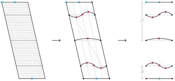
A study of many different panels featuring varying degrees of cold-bending and edge curvature led to the derivation of a sort of "shape function". This is inspired by the shape functions used in Finite Element Analysis, which use the corner points of an element and then define how to interpolate values for locations between those points. In much the same way, we will define a set of points, and then interpolate the surface geometry between them.
Through a series of geometric investigations, it was found that the around the 1/6 portion of the panel, a section through the shape would create differing types of curves - sometimes single curvature, sometimes reverse curvature. Using three sample points across the line, one can roughly define the curve, and use the interpolation in NURBS packages to create the continuous shape.
It is worth noting at this point, that the true sectional curve at these locations may not precisely match an interpolated NURBS curve, but the deviations were found to be inconsequential.
Across the middle of the panel, it was found that section curves cut through a number of simulations never revealed a reversal of curvature, and could be adequately defined by its end points and a central point.
Therefore, with the bounding shape as a given input, it was determined that, for this application, the 7 points could be used to determine the cross-s ectional shape of the panel at the given locations. Thiscreates a set up with three inputs, and 7 parameters that can be measured.
![]()
By generating 3D material simulations for thousands and thousands of panels, a database is created that maps the three inputs to the seven outputs on a panel-by-panel basis.
4.2. Automation of Finite Element Analysis
Because thousands of simulations needed to be defined, modelled, solved, and interrogated, a sequence of scripts were developed to automate this process. This was built primarily in Rhino 3d and Grasshopper, with a custom-built library that enables interaction with Strand7. One script simulates 3D-to-2D, and the other 2D-to-3D, along with some features that allow for querying the Strand 7 results, recording things like deformation, stress, and model convergence.
In order to produce the sample data to train the Machine Learning model, an initial “flattening” routine is first executed on all of the panels on the project.
4.3. Training the ML Model
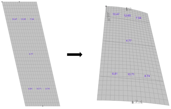
The 3 input parameters are simply given by the setout wireframe geometry and can be measured directly. Then an initial estimate of the surface is used, using the available methods in the NURBS package (Rhino 3D, in this case). This surface is then used to create an FEA simulation of forcing the panel from 3D to 2D.
The “flattened” shape will not be a correct one – as mentioned earlier, the NURBS surface cannot be truly flattened. There will be residual curvature in portions of the panel. However, the shape is then traced, and a new simulation is created with this flat, 2D outline, pushing the panel from 2D to 3D. Thereby giving us an approximation of what the real surface geometry will be, having started with a flat shape that is close to the correct shape. That cold-bent shape is then measured at the 7 specified points, and an entry is created in the database along with the 3 input parameters.
The compiled results are then ingested into the ML training step. We employ a technique called “multivariate polynomial regression” to create a best-fit mapping from the 3 inputs to the 7 outputs.There is a wide variety of algorithms that can be used to create this mapping, and the selection of one algorithm over another is a critical influence on the accuracy and behaviour of a Machine Learning model. It takes some experience and experimentation to determine the optimal algorithm for a given scenario, so a full exposition would be a bit beyond the scope of this paper.
4.4. Machine Learning Shape Prediction Loop
With the model having been trained on a set of initial approximations, the process for the predicting the final shape follows this sequence.
- Measure the 3 input parameters from the wireframe
- Predict the final 3-dimensional shape
- Execute the flattening simulation
- Trace the resulting 2D geometry
- Execute the cold bending simulation, back to the 3D shape
- Test the result against the design wireframe
- If outside of tolerance, measure the shape parameters, add them to the database, retrain the model, and re-execute the loop
- Otherwise, accept the result, and produce a fabrication drawing.
The 7th item re-trains the model when its results fall outside of acceptable limits, which adds another layer of “training”, by constantly improving the mapping of parameters. At the end of this process, the output is actually a very simple .DXF file that is sent to a CNC glass cutting machine, along with a PDF that the factory can use to measure the panel as a form of Quality Control.
5. Results and Future Study
Broadly speaking, the training algorithm allowed for the accurate fabrication of approximately 3,500 unique pieces of glass. Edge deviations were reduced from 6.5mm to less than 1.0mm. In this sense, the strategy achieved the desired result of maintaining a close adherence to the linear shape of the framing and preventing any issues that would arise from an unmanaged narrowing of the panels.
Perhaps more interesting is the behavior of the glass panels at these extreme degrees of cold-bending. Whenever discussing the upper bounds of cold-bending, "snap-through" buckling is an important consideration. This has been studied for many years and is covered much more extensively elsewhere (Bensend 2015, Bensend 2016, among others).
Much of the existing research, however, regards panels that are rectangular in shape. The panels here have two significant differences: their parallelogram shape, and curvature of one or more edges. In rectangular panels, the overall behavior at high levels of deformation is for the panel to fall into a lower energy state, whereby it "folds" along a diagonal. With the parallelogram geometry, there are two diagonals, which have different lengths and different internal angles. The longer diagonal terminates within acute angles, while the shorter cuts across obtuse angles.
One may expect that the panel would fold across the short diagonal, given the obtuse internal angle at the end will be easier to "fold" within, and the smaller diagonal dimension suggests that it will develop the dominant stiffness first. The curvature of one or both edges, of course imposes additional rigidity, which significantly affects the stability of the panel, as well as its deformation pattern.
In many cases, however, the center of the panel becomes very flat, even as the rest of the panel is curving significantly. We speculate that perhaps this is indeed the same diagonal stiffening that occurs in studies of rectilinear panels, but in this case the “ridge” that is forming is not from corner-to-corner, but across the center of the panel.
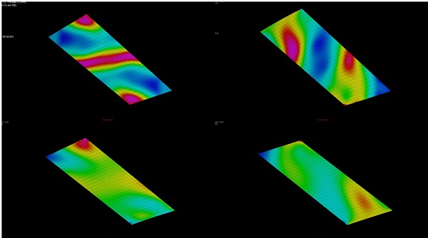
Further, while the 6 shape parameters within the 1/6 zone of the panels have significant interdependence with the input variables, the curvature across the center of the panel proved to be entirely independent of the edge curvature, and dependent only on the out-of-plane dimension. This leads to a very interesting result, where the curvature across the center of the panel can be seen to be increasingly convex in the lower degrees of deformation, then begin to flatten out, and eventually invert into a concave geometry at very high levels of deformation.
Because cold-bending is inherently a technique for resolving non-planar architectural geometries, the majority of panels in a given solution will be non-rectangular. Understanding the deformation of cold-bent, non-rectangular quadrilaterals will be important as the limits of elastic deformation are tested; a parametric study examining how the degree of non-rectangularity of a panel influences the buckling mechanisms of cold bending could prove to be very useful.
As building designs continue to push the limits on what is achievable with architectural glazing, we hope this study provides insight into mechanisms and considerations that affect cold-bent glass when it is pushed to an extreme degree. Further, as Machine Learning becomes an ever-more accessible tool, its utility as an analytic technique may prove very valuable, especially in circumstances where the interdependence of design factors is difficult to derive through conventional methods of calculation or analysis.
Acknowledgements
The authors would like to thank all the people that contributed to the realization of this ambitious and cutting-edge project. From Foster and Partners and their visionary design, to the contractors who have brought it into reality, Hyundai Engineering & Construction and midmac | MIC Construction. In particular we thank the façade contractor Alutec, who took on the challenge of producing these panels and included us as close partners throughout.
References
Bathaee, Y.: The Artificial Intelligence Black Box and the Failure of Intent and Causation. Harvard Journal of Law & Technology 31, 2. (2018)
Beer, B.: Free-Form Cold-Bent Façades and All-Glass Structures - Design and Value Engineering Challenges. Glass Performance Days 2017 Proceedings, Glass Performance Days, Tampere (2017)
Beer, B.: Options for Complex Geometry Facades – Single Corner vs. Free Form Cold-Bending. Glass Performance Days 2019 Proceedings, Glass Performance Days, Tampere (2019)
Bensend, A.: Beneath the surface: buckling of cold formed glass. In: Glass Performance Days 2015 Conference Proceedings, pp. 241-246, Glass Performance Days, Tampere, 24-26 June 2015
Bensend, A.: Maximizing the twist of cold formed glazing. In: Challenging Glass 5 Conference on Architectural and Structural Applications of Glass. Belis, Bos, & Louter (eds.), pp. 65-80, Ghent University, Belgium (2016)
Bensend, A.: The Effects of Cold Warping on Glass Stiffness. In: Challenging Glass 6 Conference on Architectural and Structural Applications of Glass. Louter, Box, Belis, Veer, Nijsse (eds.), Delft University of Technology (2018)
Datsiou, K.C.: Design and Performance of Cold Bent Glass. University of Cambridge (2017)
Galuppi, L., Royer-Carfagni, G: Optimal cold bending of laminated glass. International Journal of Solids and Structures 67-68 (2015).
Gavriil, K., Guseinov, R., et al.: Computational Design of Cold Bent Glass Facades. ACM Trans. Graph., Vol. 39, No. 6 (2020)
Gopal, N.: The consequences of panelisation on visual inconsistency of curved glass facades. University of Bath (2015)
Kimberlain, J: Durability of Structural Silicone Sealant in Cold Bent Glazing Design. Glass Performance Days 2019 Proceedings, Glass Performance Days, Tampere (2019)
Nardini, V., Hilcken J.: Mistral Tower: Value of System Design, Manufacturing and Installation in Cold Bent SSG Units. Challenging Glass 6 Conference on Architectural and Structural Applications of Glass. Louter, Box, Belis, Veer, Nijsse (eds.), Delft University of Technology (2018)
RWDI: Orbital Stack AI. https://orbitalstack.com/ Accessed 28 May 2022
Streel, A., Bibal A., et al.: Explaining the Black Box – When Law Controls AI. Centre on Regulation in Europe (2020).