First presented at GPD 2019
As more skins with complex geometry are built, design teams need to engage consultants and international industry experts to define the properties and constraints of curved insulated glass units in line with relevant standards and performance. This paper explores the traditional manufacturing capabilities, processes, and further investigates the advantages and structural performance of these glass products.
The stiffness gained from curvature in fact presents an opportunity to decrease the visual mass of mullions along straight edges. Thoughtful consideration is also given to address redistributed forces, buckling, and increased effects of climatic loads on a sealed interspace with flexible boundaries. The structural performance and design requirements are compared for insulated glass units with flat, shallow and tight curvature using a comprehensive glass, air, and silicone finite element model. Based on this study, suggestions for specification and analysis of curved insulated glass units is provided.
Introduction
The use of cylindrically curved insulated glass facades has emerged as a novel solution to meet both aesthetic and energy performance objectives. The stiffness gained from curvature has been recognized as a particular advantage over flat glass, decreasing support requirements and improving sightlines, or increasing spans. As a consequence of improved stiffness, curved Insulated Glass Units (IGU) have a reduced ability to equalize internal and atmospheric pressure changes through pillowing compared to flat units.
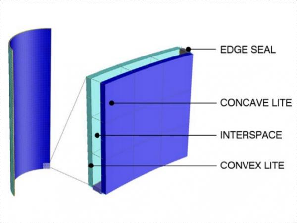
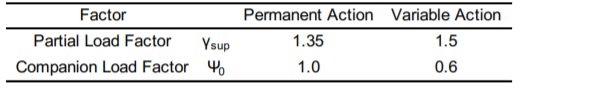
Knowledge of fabrication capabilities and structural behavior is critical to inform the design of curved glass units. This paper explores the parameters to be considered in the design of a curved IGU and the effects of pressure equalization on cylindrical units by comparing a flat IGU to units with shallow and tight curvature (Figure 1) using a comprehensive glass, gas, and silicone finite element model.
Curved Glass Fabrication and Considerations
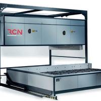
Cylindrically curved glass for architectural use is formed either by: 1) tempered bending with controlled quenching (fast cooling) to achieve a desired residual compressive surface stress distribution, or 2) slumping over a form followed by annealing (slow cooling) to relax residual stresses. Tempered bent glass dimensions are restricted by the radius of curvature and size of furnaces available in industry. Slumped glass can achieve a wider range of geometries, and as a rule of thumb can provide superior optical quality when compatible with strength requirements.
When designing a curved IGU, the following factors should be considered:
1. Coating: When a coating to achieve solar, thermal or aesthetic properties is required, attention should be paid to the type of coating and position of the coating in the IGU. While pyrolytic - ‘hard’ - coatings can be used on both concave and convex surfaces, approved - ‘soft’ - sputter coatings can currently be used on the concave surface without damage from rollers located on the convex surface in tempered bending ovens. Glass benders continue to investigate new techniques to offer soft coatings on either surface.
2. Glass type: Imperfections may be more visible when clear glass is used in lieu of low-iron with tempered glass compared to annealed or heat strengthened. Tempered glass is more prone to roller wave distortion on reflective coatings and iridescence (anisotropy) from uneven quenching. Laminated heat strengthened glass can be selected for better visual quality if compatible with the project constraints.
3. Glass thickness: Distortions and tolerances of fabrication will change depending on the type of heat treatment and thickness. Tolerances normally considered on a bent panel include local bow, twist deviations and accuracy of overall bending or deviation from glass thickness.
4. Radius of bending: Each glass bender has specific manufacturing limitations for the radii, girths and height of rise. It is advisable to confirm the latest requirements with the suppliers in the early phases of the project to understand compatibility of bending methods.
5. Number of glass plies: Laminated heat strengthened glass is also considered in certain cases as an alternative to tempered monolithic panels. Tolerances shall be discussed with the glass bender to assess if the interlayer can bridge the gap between multiple glass layers with different tolerances which can be cumulative.
6. In order to verify the aesthetics of the bespoke glass unit, review of material and progressive visual mockups at each design phase is recommended. The specimen shall be inspected under a diffuse light and not direct sunlight, at a distance greater than 1.5 m.
7. Thermal shock risks: While annealed slumped products are favorable when uncoated glass is used; coated annealed glass is at an elevated risk of breakage from thermal shock.
8. Site breakage: Installation of bent panels shall be studied in detail for compatibility with the glazing system tolerances and deformation. This is to limit additional stresses caused by unintended cold bending by forcing an edge to conform to the tolerances of the framing system.
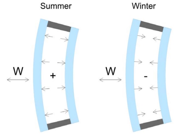
9. Equalization of IGU cavities: IGU are manufactured with a hermetically sealed gas cavity which are sensitive to pressure changes due to difference in elevation, seasonal Download presentation - 31 - GPD Glass Performance Days 2019 fluctuations in climate from barometric pressure, and variations of interspace gas temperature (Figure 2). The ability of an IGU to equalize internal pressures through pillowing is restricted by the stiffness gained through curvature. IGU which restrict equalization can develop extreme internal pressures on glass and seals causing lites to come into contact, resulting in premature failure of seals or glass breakage. Uncertainty exists regarding the proportion of equalization and confined internal design pressure.
The authors have observed that curved IGU are frequently specified on the basis of flat unit structural performance, without consideration of curvature stiffness or equalization. The effects of curvature were compared with the equivalent flat unit to assess curved IGU performance to enhance designer’s knowledge.
Equalization of IGU - A Comparative Study
Seasonal climatic loads generally have limited impact on the efficient design of balanced glass thickness, temper, or dimensions of the secondary seal. Analytical guidance on isochoric actions on IGU are not currently addressed in ASTM [1] or Australian [2] standards.
The effects of elevation change can have a substantial impact on the secondary silicone seal size. Secondary silicone sealant is typically designed for 5% of the transient design capacity for permanent actions. Curved glass fabricators consulted for this study regularly install temporary breather tubes on curved IGU to eliminate elevation effects during transportation to the curtainwall fabricator or site.
The structural performance of a 3.0 m tall by 1.5 m wide rectangular IGU with a 2:1 aspect ratio have been evaluated at flat, shallow (5° to 30°), and tight (60° to 120°) cylindrical curvature. An IGU consisting of symmetric 8mm lites with a 7.7mm minimum thickness [3] with a 16mm air filled interspace was selected on the basis of deflection efficiency for a 2 kPa unfactored wind load representative of high-rise building corners.
It is often possible to reduce or eliminate support at straight edges of curved glass due to stiffness gained from curvature. Rigid support is provided at curved edges, and along all edges of the flat IGU. Flexible support is provided at straight edges of curved glass units that would otherwise deflect more than L/175 for lateral loads (IGU curved at 5° to 15° for this study).
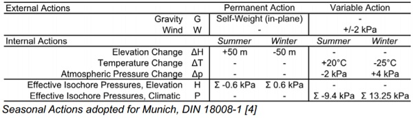
Seasonal climatic loads affecting interspace temperature and barometric pressure have been adopted from Table 2, DIN 18008-1 [4]. Change in elevation was reduced to +/- 50 m, respective of the unfavorable seasonal combination, so that edge seals of curved units could be designable for permanent actions. Load actions are summarized in Table 1. Partial load factors and companion load factors found in prEN 16612 [5] for flat units are intended for a reduced consequence class. The authors did not find a lower consequence class appropriate for analysis of glass with stability concerns. For this assessment, partial load and companion factors from DIN 18008-1 [4] are adopted as summarized in Table 2 for use with ULS & SLS load combinations [5].
A geometrically compatible finite element model representing glass, air, and silicone was used for the comparative study of flat and curved IGUs. For practical comparison, simplifications of spacer and edge seal mechanics have been made on the basis that glass does not develop a bending moment at the edges. This assumption is to be considered valid where: a) edge rotations are small, or b) the secondary seal is sufficiently narrow where edge rotations are large.
The Strand7 [6] model was composed of gradually curved QUAD8 plate elements for glass and silicone and HEX20 brick fluid elements representing air (Figure 3). Subdivision of the plate elements for glass was approximately 50 mm square. A pattern of releases and constraints allowed the fluid to be contained by the bounding perimeter
The secondary silicone seal for tensile performance was modeled as DOWSIL 3363 with Mooney-Rivlin 2-Parameter Hyperelastic Properties [7], attributed with rotationally released edges. Contact connection elements at the perimeter were representative of the spacer’s compressive properties. The secondary seal was given an increased bite width by adjustment of element thickness. The initial bite size assumption conservatively restricted elongation, resulting in higher gas pressures, without the need to iterate to optimized design dimensions.
Observations and Results
The results of curved IGU analysis fell into two groups: buckling susceptible and stiffness controlled. IGU within the stiffness controlled group exhibited clear trends concerning formed gas pressure, glass stresses, deflection, and edge seal forces. Post-buckled results from IGU curved at 5° to 15° fell outside of these trends due to the snapthrough buckling phenomena observed in the analytical models.
Due to potential for visual discomfort from excessive deflections, inelastic stress redistribution, and potential damage to seals from twisting, buckling was regarded as a failure as opined by Bensend [8] for buckling of cold bent curved glass. Buckling susceptible units were excluded from the comparison of stiffness controlled units.
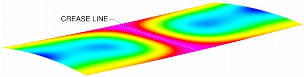
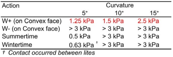
In order to evaluate curved glass buckling capacity, lateral load increments for either wind or isochore pressure were applied to the comprehensive models with appropriate boundary conditions. A geometrically nonlinear static analysis was performed and the resulting force-displacement curves were used to identify the onset of buckling (Table 3) where curvature decreases at the center and a crease forms (Figure 4).
To understand if the glass will buckle from a single action, this can be a valuable first step prior to checking all load combinations. The buckling study showed that wind loading applied opposite the direction of curvature led to the onset of buckling at a load less than the ULS design wind load. In addition, the shallow 5° IGU exhibited buckling under isochore pressures. Loads applied in the same direction as the curvature did not lead to buckling. It should be noted that given the limited number of cases studied in this effort, a sensitivity study on buckling effects is warranted for other IGU sizes or thicknesses.
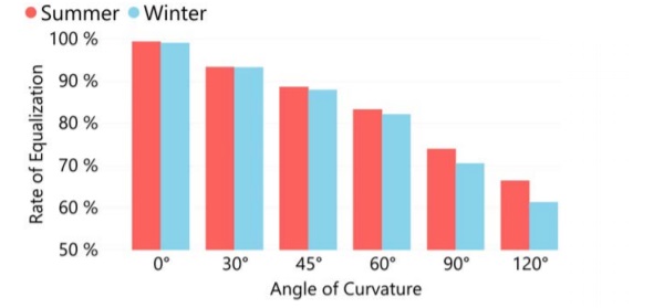
The formed gas pressure due to unequalized isocore loads in the IGU gas ranged from 0.1 kPa to 5.0 kPa in the summertime and 0.2 kPa to 8.0 kPa in the wintertime for seasonal ULS combinations. The equalization rate of 99% for the flat IGU decreased to 61% for the 120° curved IGU (Figure 5). The resulting isochore pressures exceeded the magnitude of wind.
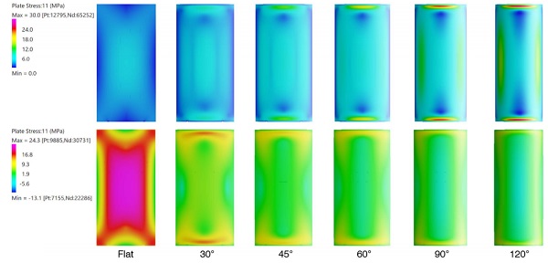
Flat glass supported on 4 edges developed a stress field located at the center of the pane. With curvature, peak stress fields were observed to redistribute from the center and concentrate along perimeter regions (Figure 6).
Compatibility of curvature with a reduced glass edge capacity and enameled frit is an important consideration during design. Curved glass that is not susceptible to buckling under design wind loads can frequently be designed as unsupported along straight edges. Support was found not to be required where θ ≥ 30° in the sample set. Deflection patterns from equalization of isochore pressures were compared with deflection from wind load (Figure 7).

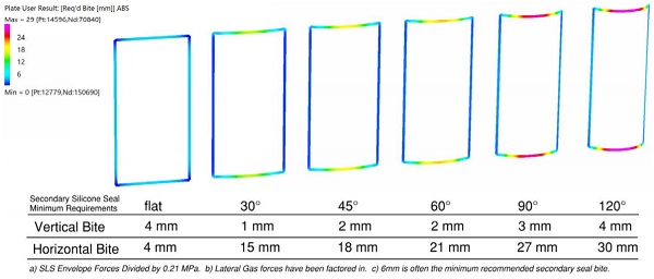
With curvature, the redistribution of forces along the edge seal coincided with the rise of internal pressures. A concentration of edge seal forces was observed on the curved edge. Required secondary silicone seal dimensions are compared in Figure 8. Edge seal requirements [9] due to a permanent +50 m elevation change were determined to be of a similar magnitude.
Conclusion & Summary
In conclusion, curvature has been observed to influence fabrication, structural performance, and aesthetic outcomes of IGU. Thoughtful consideration of fabrication capabilities and structural behavior is recommended at early project stages to identify compatible design solutions. It has been demonstrated by comparison of structural behavior that specification of curved glass on the basis of flat glass design is not appropriate.
For example, adoption of shallow curvature to glass can introduce a buckling sensitivity to glass that otherwise had adequate performance when flat. Adoption of any curvature decreases the IGU’s ability to equalize for changes in elevation and seasonal climatic effects, resulting in unequalized internal pressures that cannot be neglected.
Design standards could benefit from further clarity on the magnitude and combination of isocore effects to stay current with fabrication capabilities and market trends. A collaborative effort between the owner, designer, and fabricator will help ensure high-performing, reliable, and aesthetically pleasing designs with curved IGU are achieved.
References
[1] ASTM E1300-16, 2016. “Standard Practice for Determining Load Resistance of Glass Buildings,” ASTM International, West Conshohocken, PA.
[2] AS 1288-2006 (R2016), 2016. “Glass in buildings - Selection and installation,” Standards Australia, Sydney.
[3] BS EN 572-2:2012, 2012. “Glass in building. Basic soda lime silicate glass products. Float glass,” BSI Standards Limited, The British Standards Institution, London.
[4] DIN 18008-1:2010-12, 2012. “Glass in building - Design and construction rules - Part 1: Terms and general bases, English Translation of DIN 18008-1:2010-12,” Beuth Verlag GmbH. DIN Deutsches Institut für Normung e. V., Berlin.
[5] prEN 16612:2017, 2017. “Glass in building - Determination of the lateral load resistance of glass panels by calculation,” BSI Standards Limited, The British Standards Institution, London.
[6] Strand7, 2019. “Strand7 Finite Element Software”, R3 Preview, Strand7 Pty Limited, Sydney
[7] Dow, 2018. “Behavioral Data Sheet. DOWSIL 3363 Insulating Glass Sealant,” The Dow Chemical Company, Form No. 63-6691-01.
[8] Bensend, A. “Beneath the Surface: Buckling of Cold Formed Glass,” Glass Performance Days 2015 Conference Proceedings, pp. 241-246, Glass Performance Days, Tampere, 24-26 June 2015
[9] Dow, 2018. “Declaration of Performance. No SNF_DOP_005,” The Dow Chemical Company, Form No. 62-1886-01 A, Version 3.
Acknowledgements
Thank you to the entire Strand7 team, Anne Delvaux with Beaufort Analysis, and the following glass fabricators: Cricursa, Cristacurva, Sedak, and Sunglass.