However, with the right use, there is so much more possible with glass! Mechanically, glass has the capacity to withstand high compression forces and also high tension forces if heat- or chemically-treated. As knowledge and production methods progresses, larger glass units can be produced as well as designed. In the last decades, glass has been used more and more in major structural elements, by applying it as glass fins. It can be bonded to steel to create special composite structures. So-called hot or cold bent glass is also possible in order to create single or double curved elements. Combining these possibilities of glass one can reach one of the ideal concepts of architect and engineers, almost invisible transparent load-bearing elements in every shape: engineered transparency!
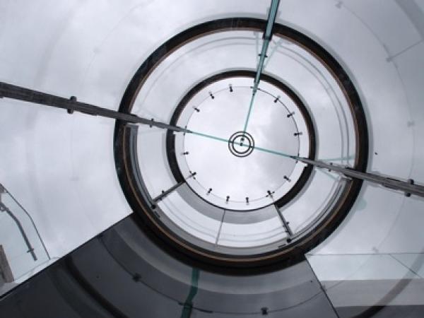
Figure 1: Glass elevator shaft for Royal Picture Gallery Mauritshuis in The Hague
Credits: Jacqueline Knudsen, ArchitectuurNL
Structural properties
The particular material properties of glass greatly influence how a system is designed and built. Glass is a brittle material, which means that glass will not plastically deform prior to failure. Glass will fail once it surpasses its elastic deformation and reaches its maximum yield stress. One small peak stress can lead to the breakage of the total glass pane. Tension stresses are always normative in glass design as glass is much stronger in compression. Heat treating or chemical strengthening increases the overall tensile strength of glass by introducing pre-stress; compression stresses at the glass surface where fracture starts and tension stresses in the center of the section. When glass breaks, the breakage pattern reveals the pre-stress (stored energy) that was present before. The higher the pre-stress, the smaller the glass particles. Due to the nature of the pre-stress, allowed tension stresses are different in the center of a glass pane than at the edge of a glass pane. Also, allowable stresses are time dependent. For example, allowable stresses in case of snow load are significant lower than in case of wind load.
Glass fin structures
Glass fins (or beams) are the most common used structural element in structural glazing. In horizontal position one can compare it with a steel girder, which supports roof or floor. In vertical position one can compare it with a wooden column or aluminium mullion. Glass fins represent one of the most transparent forms of structures. One of the earliest use of glass fins as structural element date back to the 1950´s and the application of the Hahn suspended glass system at Maison de la Radio in Paris, which used single ply glass fins as stiffeners to reduce deflection. In the following years this system evolved to allow even larger glass facades, with Norman Foster’s Willis Faber & Dumas building as one of the first modern glass fins on a commercial scale. However, due to production limitations, maximum dimensions of the glass parts were just a couple of meters. Even until recently, most float glass was produced with standard maximum lengths of 3,6 – 6m depending on the manufacturer. Hence, in the past fins longer than 6m have typically been composed of multiple pieces spliced end-to-end, with moment stiff coupling elements between the pieces. Just after the millennium the possibility to produce larger fins by new tempering ovens initiated in the following years the possibility to make glass structures with full glass fins as the major structural beams. A development partly driven by the high standards set by the worldwide ‘flagship’ Apple stores, engineered by Eckersley O'Callaghan. Current maximum measurements in reach of manufacturers in China and Germany are around 18m by 3,6m, including lamination, hot bending, coating and tempering. However, these measurements require extreme investments of the manufacturers in material, knowledge and time to master production.
.jpg)
Figure 2: Victoria & Albert Museum in London,
Credits: Octatube Delft
Recent years Octatube have designed, developed and built numerous projects with glass fins, e.g. translucent glass fins for the V&A Museum in London (image 2), quadruple laminated main glass fins for the roof of the Municipal Museum in the Hague, where glass fins span 10m (image 3) and glass fins for roof and façade of the Van Gogh Museum in Amsterdam that span up to 12m (image 4). All these projects display glass fins as main component for the load bearing structures in roof and façade. Their safety behavior after breakage was reason for research as well. Execution of the safety philosophy of glass divers per country, but always leads to a safe situation in which progressive collapse and a second load bearing system is taken into account.
.jpg)
Figure 3: Municipal Museum in the Hague
Credits: Octatube Delft
If a monolithic element is broken the glass and all it supports will most likely collapse. Laminated glass solves this issue of brittleness. Glass plates are bonded to each other to make sure they always stay in place when they break. When one glass plate breaks, the neighboring will keep it in position. When all plates break, the supports are designed to prevent the glass from falling and can often remain in place until the area can be cleared of occupants. These failure scenarios have been part of experimental testing at Octatube, to proof/convince third parties. For example, the full breakage of a glass fin existing of fully tempered glass plates as shown in image 5.
Stabilizing glass
Next to using glass as primary structural elements, glass is often used by Octatube to stabilize other structural members. For example, in the design of a glass façade for Centro de Arte de la Fundación Botín, designed by Renzo Piano, slender stainless steel mullions (22mm x 220mm) up to 16m in length were supported sideways by the glass units in between them. In plane, the glass units are very stiff due to its large width to height ratio. To act as bracing the connection between the glass and steel is very important. For this connection, often small blocks of the material Polyoxymethylene (POM) are used due to its high stiffness and good strength properties compared to rubbers, but relatively low stiffness compared to glass (Glass E=70.000 N/mm2; POM E=3.000 N/mm2) to minimize peak stresses in the glass. Only compression forces are transferred through the connection, which, as mentioned before, is favorable as glass has a great capacity to withstand compression forces.
.jpg)
Figure 4: Roof and facade of the Van Gogh Museum in Amsterdam
Credits: Octatube Delft
Likewise for Octatube’s most recent project, expansion of the Van Gogh Museum in Amsterdam, glass is used to stabilize other elements. In this case, the insulated glass units in the façade and roof are used to stabilize glass fins mentioned earlier. Therefore, in this case glass supports glass. The connection between glass fins and glass units is made by bonding stainless steel rectangular hollow sections to the glass fins on which blocks of POM are screwed.
.jpg)
Figure 5: Failure of tempered glass after a bending test at Octatube
Credits: Octatube Delft
For the glass elevator of the Royal Picture Gallery Mauritshuis in The Hague (image 6a), glass is even used as the main stability system. Vertical glass fins act as columns and hot bend laminated glass plates act as bracing. The connections between glass fins and bend glass units are designed to generate a compression diagonal in the curved glass. This is done by two blocks near the corner of the pane as showed in image 6b. The exact position and measurements of these blocks is very important as this determines the tension stresses that also exist when a compression diagonal is present.
Instead of ‘simply’ locking up the glass units by POM elements, also mechanical connections between the glass units can stabilize a glass structure as done at the Dreefgebouw in Haarlem (image 7). Moment connections transfer forces between the glass units in the façade and roof to create one connected glass enclosure. To ensure the load introduction in all glass panes of the laminated unit, special injection mortar is used that fills the space between glass and steel connector.
.jpg)
Figure 6: a) Glass elevator shaft of the Royal Picture Gallery Mauritshuis in the Hague,
Credits: a)Luuk Kramer, b) Octatube Delft
.jpg)
Figure 6: b) Sketch of structural system and FEM-Model of the corner of a glass pane
Credits: a)Luuk Kramer, b) Octatube Delft
.jpg)
Figure 7: Stability by mechanical glass connections in Dreefgebouw, Haarlem
Credits: Octatube, Delft
Future: Robust, transparent and efficient buildings
Laminated glass is tough, resilient and not prone to sudden breakage and would greatly deform before yielding. A great material to build with and to optimize our structures with. With the latest glass engineering milestones like the Zorlu Center Apple Store in Istanbul, absolute transparency is reached by a total absence of steel fixings. As well as the extension of the Van Gogh Museum where glass is omnipresent, i.e. to stiffen the steel structure and to use as main structure of the glass staircase, shows the diversity of glass usage. These concepts of architects included fully transparent structures. Concepts that only can be reached with an intensive engineering process. What will be the possibilities in the future, what will be our boundaries? Let architects challenge the engineers and let the engineers inspire the architects!
.jpg)
Figure 8: Van Gogh Museum, Amsterdam, by night
Credits: Jan Kees Steenman, Van Gogh Museum
Footnote:
The title of this article is taken from a biannually glass conference held in Düsseldorf. Together with Challenging Glass and Glass Performance Days (GPD) the leading conferences on glass engineering. Check those conferences if you want to know more about state of the art glass engineering.
Authors: Wouter van der Sluis & Chris Noteboom, Octatube Delft