Abstract
Mechanically stiff interlayers extend the performance of laminated glass fins and provide improved design solutions for glass façades. The enhanced flexural behavior and strength benefits associated with a stiff interlayer enables longer, thinner and narrower fin profiles with extended structural performance versus conventional PVB laminates. There are a limited number of codes and standards that address the engineering of glass fins. The Australian standard AS 1288 is an important reference for monolithic glass fin design and treats the buckling/collapse condition for several boundary conditions, but does not address laminated glass.
Façade engineers often use published buckling formulas and finite element analysis to design laminated glass fins. One design approach is to neglect the shear properties of the laminate and treat the fin as if it were fully coupled. The total glass thickness is then used with published monolithic glass buckling formulas. This research challenges this approach. Here we review full-scale mechanical testing, finite element techniques, and published buckling equations of structural glass fins for eight different constructions, demonstrating the effects of different interlayers in laminated glass fins.
Introduction
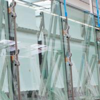
For nearly 50 years, glass has been used as structural elements in glass fin applications. These applications include interior and exterior projects, supporting facades, canopies, storefronts, curtain walls and skylights. The first fin applications were primarily monolithic fully tempered glass, using thick (19mm) lites. Fully tempered glass has many advantages over annealed or heat strengthened glass. When tempered glass fails, it breaks into smaller, safer pieces. Fully tempered glass also has inherent flaws as it can be prone to nickel sulfide inclusions, which can cause spontaneous breakage.
Heat soaking can be used to prevent against spontaneous breakage. However, once monolithic fully tempered glass is broken there is no residual barrier, and no post glass breakage strength. Laminated glass is used address this issue. In addition to the post-breakage strength issues of monolithic glass, as fins get longer and designed for higher loads, it is no longer possible to achieve these designs with monolithic glass due to thickness limitations. Laminated glass allows for thicknesses greater than 25mm, increasing the applications for glass fins.
Standard PVB was originally developed for automotive windshields in the 1930s. It is a flexible interlayer that offers some post glass breakage stability, and can help to secure the glass in the framing after breakage. PVB does not offer post glass breakage strength after all plies are broken. Standard PVB has been used in glass fins, however due to the softness of the interlayer; the glass lites must be thicker in order to carry the same load as a monolithic fin. In the 1990s, DuPont SentryGlas® (Ionoplast) was developed as a structural interlayer material, capable of passing hurricane code requirements for use in high wind zones.
Ionoplast is 100 times stiffer than standard PVB, and five times more tear resistant. These properties allow the interlayer to more effectively couple plies of glass, providing for a stiffer composite laminate. This allows a laminate made with Ionoplast to have superior post glass breakage performance and retention.
Due to the long slender nature of fins, the typical failure mode is lateral torsional buckling. The objective for this paper is to compare several mathematical approaches to fin design in regards to lateral torsional buckling, including both monolithic and laminated structures. In addition, we will discuss full scale testing to further validate these equations for use on both monolithic and laminated fins.
Theory
At this time, there are very few references in codes and standards regarding glass fins. One of the few is the Australian Standard AS 1288 [2]. This standard addresses fin buckling, providing formulas for calculating critical elastic values for beams with and without buckling restraints, as well as continuous restraints. For example, Appendix C3 offers an equation for “Beams with no intermediate buckling restraints”, as shown in Equation 1 below.
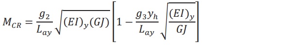
In this equation, MCR represents the critical buckling moment of the fin, g2 and g3 are constants based on how the fin is supported, Lay is the unsupported distances between rigid buckling restraints, (EI)y is the rigidity against bending about the minor axis, GJ is the torsional rigidity, and yh is the distance above the centroid of the location of the load.
As can be seen in the equation, there is no reference to the type of interlayer used. The equation is entirely based on the geometry of the fin, how it is supported, location of load, and the type of material (glass). This equation, and the others presented in AS 1288, work well for monolithic fins, however there is no option presented for laminated fins. A glass fin designer can only make an assumption as to the loss of torsional rigidity due to the loss of shear coupling caused by the interlayer. In some cases, designers errantly add the ply thicknesses of the laminate together and apply the AS1288 equations, ignoring the effects of the interlayer.
An additional method is outlined in the work of Dr. Andreas Luible [1]. He has presented a direct equation connecting a laminated fin to critical buckling moment. This equation includes the elastic modulus of glass, moment of inertia of the fin, unsupported span, shear modulus of interlayer, support conditions, and loading type. Equation 2 below shows the details.

Equation 2 can be used to calculate fins with different interlayer materials, different load durations, different temperatures, different spans, different geometries, etc. Using material properties of standard PVB and Ionoplast at 50C and 3 second load durations, several designs were explored and presented in the following tables. Tables 1 and 2 below show the shear modulus of standard PVB and Ionoplast over a variety of temperatures and load durations. It is important to choose the appropriate modulus values for the given application.
![Table 1: Ionoplast Shear Modulus in MPa [4]](/sites/default/files/inline-images/Tab1_78.jpg)
![Table 2: Standard PVB Shear Modulus Values in MPa [4]](/sites/default/files/inline-images/Tab2_53.jpg)
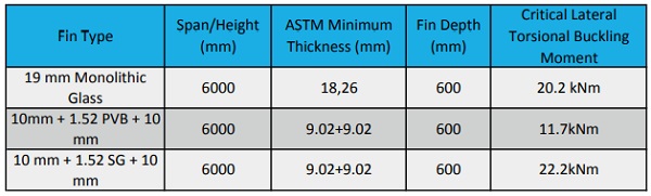
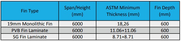
In Table 3, a 6 meter fin, simply supported, with a depth of 600mm is designed using monolithic glass, 60 mil Standard PVB (PVB), and 60 mil Ionoplast (SG). It can be seen that the buckling moment for the monolithic fin and the Ionoplast laminated fin are on the same order, however the standard PVB construction is ~40% lower than the others. This shows the major differences that interlayer can play when designing structural glass elements.
In Table 4, the same design moment has been used for all three glass fins, and the depth of the fin is allowed to change in order to reach the desired critical buckling moment. Again, the monolithic fin and the Ionoplast fin are comparable, while the Standard PVB fin must be 50% wider than the others.
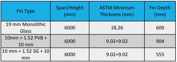
In Table 5, again the design moment has been held constant for all three constructions. This time, the glass thickness is allowed to change in order to meet the critical buckling moment. In this case, the monolithic and Ionoplast fins are comparable, while the PVB fin must have 21% thicker glass in order to attain the same critical lateral torsional buckling moment.
In all cases, the fin composed of PVB laminate would require thicker glass and or deeper fin construction in order to resist the same lateral load as the Ionoplast laminate or the monolithic glass. This has a significant architectural impact on the façade. In architecture, there is a strong desire towards having the fins as narrow as possible to maintain aesthetics and efficiency of the space. The softer PVB makes this goal more difficult to reach. In addition to reducing the aesthetics of the facade, the building structure supporting the fin wall may need to be larger to support the added weight of the fin.
The bucking equations presented by Dr. Luible and in AS1288 are excellent for many glass fin design problems. But, there are many design situations not covered by the hand formula: irregular loading patterns, continuous beams, beam-columns, etc. In these situations, computer modeling is necessary. The equations presented by Dr. Luble were compared to a finite element analysis (FEA). The analysis was performed in Abaqus Standard version 6.12 [3].
Three dimensional solid elements were used for the glass and interlayer. The glass elements (C3D8I) and interlayer elements (C3D8RH) were approximately 25mm x 25mm in size with two elements over the thickness. Elements with incompatible modes were used for the glass to remove the shear locking that is inherent with thin solid elements in bending. Interlayers are viscoelastic as they have different properties under different temperature and load durations. To simplify the analysis, linear elastic material properties were used for both the glass and interlayer.
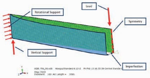
The glass fins were modeled using half symmetry. The load was applied 25mm above the front face of the glass and the end of the fin was restrained from twisting. A lateral imperfection in the RIKS analysis was added to the geometry by translating the nodes into a displaced configuration. Figure 1 below shows the modeling assumptions used in this study.
Two analysis techniques were used: Eigenvalue and RIKS. The eigenvalue analysis outputs a single buckling factor that compares with the hand formulas presented by Luible. The RIKS analysis is a more advance modeling technique typically used for unstable structures. This analysis solves for loads and displacements simultaneously, and therefore the model remains stable throughout the buckling event [3].
Testing
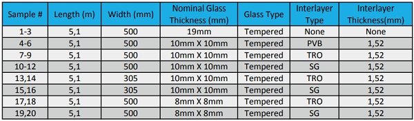
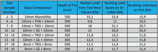
In order to validate these equations and modeling methods, mechanical testing of full scale fins was carried out. There have been several papers written on these equations in the past, but usually on lab scale fins of roughly 1m in length. To test for scalability, we designed a test using fins with a 5m span, and a depth of 500mm or 305mm. The fins had a construction of 10mm x 10mm fully tempered glass or 8mm x 8mm fully tempered glass, with a 60 mil interlayer. A 19mm monolithic fully tempered glass fin was also tested for comparison. Our study included standard PVB (PVB), Trosifol ES (TRO), and Ionoplast (SG). A total of 20 fin samples were prepared at AGNORA that included a range of fin depths and thickness, as highlighted in Table 6 below.
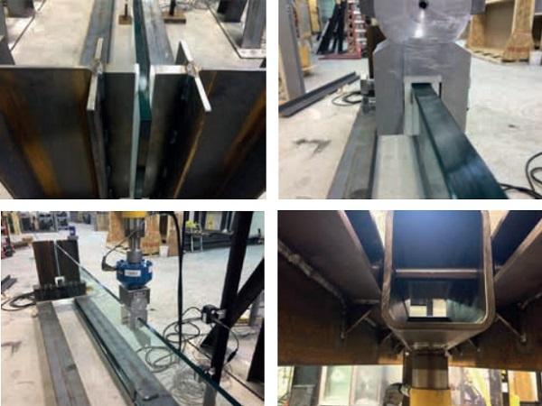
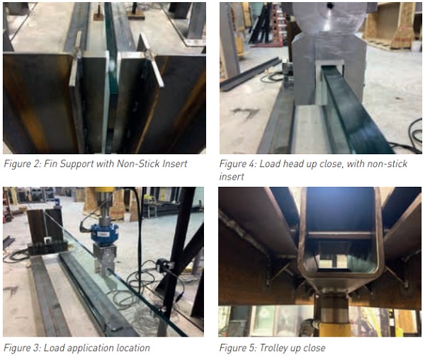
Tests were carried out at Intertek-ATI in York Pennsylvania. The test fixture was originally based on Dr. Luible’s work, scaled for larger fins. The fins were supported at both ends using steel beams and non-stick inserts to prevent end rotations. These supports can be seen in Figure 2.
The load is applied on center, using a trolley system, allowing the load to move with the fin laterally, and apply the load vertically at all times. The trolley was designed with bearings to remove as much friction as possible, and non-stick inserts were included in the load head. Figure 3, 4 and 5 below show the load head and trolley, as well as the load application point on the fin (middle of the span, top edge). Even though careful attention was made to remove the friction in the test assembly, it was not possible to create a friction free assembly as small amounts of friction will laterally brace the fin and have a significant impact on the results of the test. A lab technician had to influence the trolley by applying steady lateral translations to the carriage of approximately 6mm every 10 sec.
The samples were loaded in such a way to cause lateral torsional buckling. Displacement transducers were attached to the fin samples, as well as the trolley, to measure the displacement of the fin under the known applied load. The load was applied using a hydraulic ram, in increments of 250lbs. Once the sample reached a buckling state, the fin was no longer accepting additional load, rather the fins were in a steady state of deflection, until ultimate failure of the glass plies. For each sample mentioned in Table 6, force deflection data was collected for comparison against the mathematical expressions presented by Dr. Luible, as well as the finite element techniques laid out in this paper.
Results
The results of the test are listed below in table 7. Here, the median loads of the three tests are compared with the Dr. Luible’s equations and to the FEA. In order to accurately simulate the test, the glass in the FEA (and mathematical formulas) was changed from the minimum glass thickness in E1300 to the actual glass thickness measured with a micrometer. Also, the RIKS model was changed to reflect the actual imperfection measured on each specimen. Last, an adjustment was made to the interlayer properties to represent the lab temperature and load duration of the glass specimen.
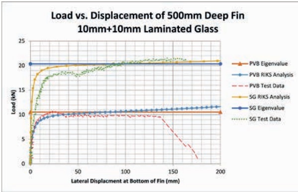
A load vs. displacement graph was created for all test specimens to compare the test to the FEA. In Figure 6, two of the twenty test results are compared. The results are for a 500mm deep fin with 10mm + 10mm glass laminated with PVB and Ionoplast (SG) Interlayers.
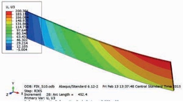
Figure 7 shows the displacement contour plot of the glass fin in its buckled shape near failure. The graph in Figure 6 shows the lateral displacement at the bottom of the fin of approximately 150mm. The top of the fin experiences over 200mm of lateral deformation before failure.
Conclusion
From the results in Table 7 and the graph in Figure 6, the following conclusions can be made:
- The buckling capacity of a glass fin with a stiff interlayer is higher than with fins with a soft interlayer. This is true when the interlayer is at room temperature.
- Glass samples with stiff interlayers were slightly stronger than monolithic glass of almost equal thickness.
- The fin tests, FEA, and Dr. Luible’s buckling equations produced similar results.
- Properly tempered glass fins experience large lateral and rotational deformations before failure.
Three methods to validate the lateral torsional buckling capacity of laminated glass fins were investigated: Dr. Luible’s equations, finite element analysis, and large scale testing. Glass fins using Ionoplast and Trosifol provides comparable lateral torsional buckling results to equivalent sized monolithic glass with additional post glass breakage stability and strength. Furthermore, stiffer interlayer materials such as SentryGlas® and Trosifol result in thinner glass, narrower geometries, resist higher loads, and are able to span longer distances in comparison with softer interlayer materials such as standard PVB. Laminated glass can be used efficiently in structural glass.
References
[1] “Stability of Load Carrying Elements of Glass”, Luible, Andreas, Crisinel, Michael
[2] “AS 1288 – 2006 Australian Standard: Glass in Buildings—Selection and Installation”, by Committee BD-007, 16 January 2006.
[3] “Abaqus 6.12 – Abaqus Theory Manual, ABAQUS Documentation”, by Dassault Systemes.
[4] http://glasslaminatingsolutions.kuraray.com/architectsengineerscorner, by Kurary, 15 May 2015