This paper was first presented at GPD 2025.
Link to the full GPD 2025 conference book: GPD_2025_ConferenceProceedingsBook.pdf

Authors: Filippo Gerin a,b, Alberto Consolaro a, Massimo Maffeis a, Gianni Royer Carfagni b
a. Maffeis Engineering SpA, Solagna (VI), Italy
b. Department of Engineering for Industrial Systems and Technologies, University of Parma, Italy
Abstract
Insulating Glass Units (IGUs) are widely used to enhance thermal and acoustic performance of windows and façades. In addition to the challenges associated with non-linear modelling of the possibly laminated glass panes, delimiting the cavities filled with air or inert gas, there is the added complexity of accurately considering the load sharing between the panes through the gas. In fact, when external loads are applied to one of the panes, its deflection alters the volume of the trapped gas, leading to a pressure variation that helps support the loaded pane while pressing the unloaded pane. Commercial software can consider this effect, but with limitations for what concerns the modelling of the gas and the possibility of analyzing curved geometries. From a constitutive point of view, the pressure variation depends nonlinearly on the volume variation which, is a highly nonlinear function of the displacements of the two surfaces that delimit the cavity. This leads, in general, to a sparse tangent stiffness matrix, which challenges the numerical solver. Many existing codes introduce linear approximations to simplify the problem, but these are not always suitable under large deformations. Anyway, without these simplifications the computation time can become excessively long. We complemented our existing inhouse FEM code, which applies to a nonlinear solid-shell model for LG, by adding a module to analyze the response of IGUs, including curved configurations, under general loading conditions. The model incorporates both geometric and constitutive nonlinearities and can readily consider variations in temperature and barometric pressure. Our numerical strategies account for the exact volumetric changes in the cavities, enabling precise determination of load-sharing effects. Results from multiple case studies are compared with those from commercial FEM software for structural analysis. While the agreement is excellent, our approach requires significantly less computational time.
Article Information
- Published by Glass Performance Days, on behalf of the author(s)
- Published as part of the Glass Performance Days Conference Proceedings, June 2025
- Editors: Jan Belis, Christian Louter & Marko Mökkönen
- This work is licensed under a Creative Commons Attribution 4.0 International (CC BY 4.0) license.
- Copyright © 2025 with the author(s)
1.Introduction
Insulating Glass Units (IGUs) consist of multiple glass panes, either monolithic or laminated, sealed along their perimeter by various types of edge seal systems. When composed of two glass plates, they are commonly referred to as Double Glazing Units (DGUs). The interpane space is filled with an inert gas, such as argon or krypton, adding desiccants to absorb any internal moisture. Numerous studies have focused on evaluating the thermal performance and sound insulation properties of IGUs (Manz et al, 2006), but more limited attention has apparently been given to assessing their structural capacity. This is enhanced by the fact that all panes share a portion of the total applied loads, a result of the interaction between the glass plates and the air/gas trapped in the interpane space (McMahon et al, 2017). Indeed, IGUs can be considered a conjugate system, with the air interlayer acting as the conjugating member. As most codes of practice recommend, any structural calculation method must account for three key effects: (i) the load sharing, i.e., actions applied to a single pane affect all other panes due to the volume change in the gas consequent to pane deflections; (ii) the changes in the external barometric pressure since the time of sealing; and (iii) the variations in the gas temperature within the cavity, which generates a variation of internal pressure.
Various methods have been proposed to evaluate the load sharing in IGUs; a synoptic comparison can be found in (Morse and Norville, 2016). ASTM E-1300 (ASTM, 2012) states that each glass pane carries a load proportional to its flexural inertia, i.e., the cube of its thickness for monolithic glass, or of its deflection-effective thickness for laminated panes. The load-share factor is therefore the ratio of the cube of a pane’s thickness to the sum of the cubes of all pane thicknesses, but this approach assumes of isochoric gas deformation and can be used only when the applied load is uniformly distributed. Feldmeier’s refined analysis (Feldmeier, 1996) considered gas volume changes from plate deflection and resulting cavity pressure, ignoring edge seal deformation, and addressed rectangular IGUs under line or concentrated loads using tabulated coefficients for volume change. EN 16612 (CEN TC/129, 2019) specifies that external-load sharing depends on individual pane stiffness, adjusted by an insulating-unit factor based on IGU dimensions, glass and gas space thicknesses, and a volume change coefficient, tabulated for rectangular IGUs and applicable only to uniform loads (wind, snow, self-weight) and changes in barometric pressure and temperature. A recent pseudo-analytical formulation (Galuppi and Royer-Carfagni, 2020a), named Betti’s Analytical Method (BAM), relies on the classical Reciprocal Work Theorem formulated by Enrico Betti in 1872. For both double and multiple IGUs (Galuppi and Royer-Carfagni, 2020b), it provides concise analytical expressions to determine the variation of gas pressure for glass panes of any shape and thickness, under various support conditions and external actions (concentrated, line and distributed loads, thermal and climatic actions). Gas deformability is modelled in isothermal processes, but adiabatic transformation can also be considered. The key advantage is that the BAM only requires evaluating the deformation of a linear-elastic plate under uniform pressure and simply supported borders. This allows for the determination of gas pressure variation under any loading type without having to calculate the corresponding deformation, reducing the need for extensive tables. The BAM approach is also mentioned in the most updated version of the new Eurocode documents for structural glass (Feldmann et al, 2023).
All methods mentioned above allow calculating the variation of gas pressure be means of a linear elastic modeling of glass plates, according to Kirchhoff-Love theory. A non-linear analysis of the glass plates can be performed a posteriori, by considering the so-calculated pressure variation as a datum, but this remains an approximation. For cases where non-linear effects are significant, a numerical approach is necessary. The commercial code SJ MEPLA (Bohmann, 2018) uses the ideal gas equation to calculate cavity volume changes from glass pane deflections, accounting for pressure nonconforming loads (e.g., point loads, bearings) and geometric non-linearity. However, the software is limited to flat geometries and is only second-order accurate. The commercial FE code Strand7 (Strand7, 2024) can consider cavities filled with ideal gas, with initial pressure. There are two ways to deal with cavities in the non-linear solver. The first is to assemble the cavity stiffness matrix; the second is to ignore the cavity stiffness matrix altogether and not assemble it at all. In the second case, equilibrium is achieved through an iterative procedure, by calculating the change in the cavity volume and the consequent change in pressure in the gas, now considered as an applied load, and repeat the procedure until volume change matches the deformation of the pressurized panes. This procedure works well when the change in cavity volume from iteration to iteration is small with respect to the initial volume of the gas. For very narrow cavities, this procedure may produce numerical instabilities that inhibit convergence.
Our in-house FEM code, as described in (Gerin et al, 2025), implements a nonlinear solid-shell model for laminated glass (Magisano et al, 2023). This is now enhanced with a specialized module, designed to evaluate the structural behavior of insulating glass units (IGUs). The module can analyze curved configurations under diverse constraints and loading scenarios, incorporating both geometric and material nonlinearities, including temperature fluctuations and barometric pressure changes. The numerical methodology constructs the cavity stiffness matrix, ensuring robustness against numerical instabilities while effectively capturing load-sharing effects. Validation through multiple case studies, compared against Strand7 structural analysis software, demonstrates strong agreement. Notably, our approach achieves these results with significantly reduced computational time.
2. Modelling
The gas entrapped in the cavity is here considered as perfect gas, satisfying the equation 𝑝V = 𝑛RT, where 𝑝, V and T are the pressure, volume and temperature respectively, while 𝑛 indicates the amount of substance and R is the ideal gas constant. Other types of constitutive equations can be used for the gas, with a similar treatment, but here we will detail only this case.
In reference configuration, at the temperature T = T₀, the gas entrapped in the cavity of volume V = V₀ is supposed to be in equilibrium with the external pressure p₀ = nRT₀/V₀, so that the glass plates are stress-free. Variations in the temperature T₀ induce a modification of the gas pressure. A change in the barometric pressure p₀ result is a difference between the internal and external pressure in the panes. When one of the external panes of the IGU is subjected to concentrated, line, or distributed loads, the resulting deflection alters the cavity volume, inducing again a variation of the gas pressure, which. redistributes the applied action to the unloaded panes (load sharing).
In our code, the glass panes, either monolithic or laminated, are numerically considered as indicated in (Gerin et al, 2025), according to the solid shell model (Magisano et al, 2023). Now, it is necessary to add the contribution from gas. The first variation of the gas energy, corresponding to a variation V + δV of the volume of the cavity, can be written in the form

Let X denote the position of a particle of the gas in the cavity in the reference configuration. After the deformation, its position is indicated by the deformation φ(X) = X + u(X), where u denotes the displacement field. The gradient of φ with respect to the refence state is obviously ∇φ = I + ∇u, being I the identity. Hence, the volume of the gas in the actual (deformed) state is given by V = ∫v₀ det(I + ∇u) dV, so that (1) becomes

To better analyze this condition, it is necessary to make explicit the variation of the determinant. To do this, we consider a variation in the deformation in the form φ + δw ᵒ φ, where the symbol “ᵒ” denotes the composition of two functions. With elementary tensor analysis, one can demonstrate that
![]()
where the last term is a surface integral on the boundary ∂V of the volume V (deformed state), being n the outer unit normal. Recalling (2), this condition indicates that the gas energy variation is only due to the variation of the component of displacement normal the actual (deformed) configuration of the cavity surface. This means that in a geometric non-linear analysis, one must consider the deformed shape of the cavity. A great simplification can be achieved in a second order approximation of geometric non-linearities, as done in SJ Mepla (Bohmann, 2018), but this is feasible only for flat geometries, and is, in general terms, not precise.
The solid shell model implemented in our in-house code naturally provides a way to calculate the volume variation of the gas. To illustrate, the reference configuration of the (possibly curved) cavity of thickness h is described by the convective curvilinear coordinates ξ = [ξ₁, ξ₂, ξ₃], with (ξ₁, ξ₂) ∈ Ω ⊂ ℝ² representing the middle surface and ξ₃ ∈ [-h/2, h/2] the thickness coordinates. The position of the point x(ξ) in the distorted (actual) configuration is given in terms of its position X(ξ) in the undistorted (reference) configuration and the displacement u(ξ), as x(ξ) = X(ξ) + u(ξ). One can write
![]()
where Xb [ξ₁, ξ₂] = X [ξ₁,ξ₂,-h/2] and Xt [ξ₁, ξ₂] = X [ξ₁,ξ₂,h/2] respectively denote the positions of the bottom and top surfaces of the cavity, which coincide with the glass surfaces that delimit the cavity. Analogously, the displacement field is defined as

where ub [ξ₁, ξ₂] = u [ξ₁,ξ₂,-h/2] and ut [ξ₁, ξ₂] = u [ξ₁,ξ₂,h/2] correspond to the bottom and top surfaces, respectively. If one indicates with

the volumes V₀ and V in the reference and actual configurations, respectively, take the form
![]()
A numerical challenge arises because the integrals in equation (7) account for contributions from all nodes along the cavity’s boundary surfaces. Consequently, the resulting Hessian matrix is dense, imposing a significant computational burden on numerical libraries designed for sparse solvers. To address this, a technique taken from (Bonet et al, 2000) is applied to reduce the influence of air layers and enhance computational efficiency. This approach differs from Strand7, which is constrained to either solving the full system or using an approximate Hessian matrix, leading to slow convergence.
3. Examples
A few representative examples can illustrate the potentiality of the code.
3.1 Monolithic IGU under pseudo-concentrated load
Consider a 3 m × 4 m IGU, composed of two monolithic glass plates, 6 mm thick, separated by a 15 mm air spacing, under a short-term load of 2 kN, distributed on a 100 mm × 100 mm area. The interlayer is representative of a PVB operating at room temperature with 3 s applied-load duration, for which the shear modulus is estimated to be G = 50 MPa.
![Fig. 1: IGU simply supported on four sides under a pseudo-concentrated force. (a) Layout and indication of the applied load. Maximum principal stress [MPa] at the tensile surfaces of the (b) top and (c) bottom pane.](/sites/default/files/inline-images/Fig1_509.jpg)
Figure 2(a) represents the layout of the element, simply supported on the four sides, with indication of the loaded area. The edge seals maintain a constant distance between the borders of the glass panes. The adopted mesh consists of 42 x 52 rectangular elements for each surface of the panes, refined to accommodate the loaded area, as indicated in Figure 2(b). The maximum principal stress S11 [MPa] on the tensile surfaces of the top and bottom panes are respectively indicated in Figures 2(b) and 2(c). The bottom pane is subjected to a distributed pressure, dictated by the variation of the gas volume in the cavity. This also helps the top pane in bearing the pseudo-concentrated applied force.
Results were successfully compared with those obtainable with a 3D mesh, employing 20 node brick elements, with a mesh size comparable with that of Figure 2(b), implemented in Stand7 (Strand7, 2010). Our code executes this case in under 2 seconds, whereas Strand7 requires approximately 1 minute with Hexa8 elements.
3.2 Curved IGU under pseudo-concentrated load
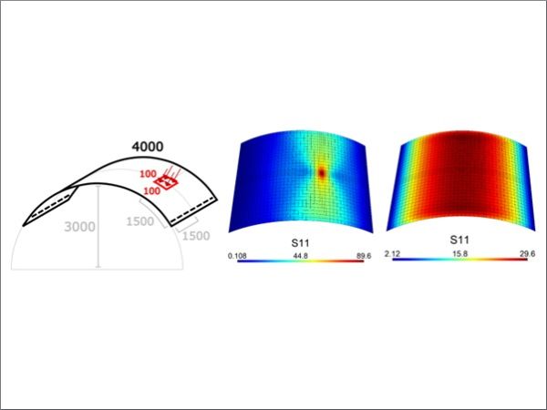
The considered problem is that of single curvature shell, with radius of curvature equal to 3000 mm, simply supported on the two straight sides, as indicated in Figure 2(a). It is made of two 6 mm glass plies separated by a 15 mm gas chamber. The structure is subjected to the action of a 1.5 kN normal load, applied on a 100 mm × 100 mm area, as indicated in the layout of Figure 3(a).
The maximum principal stress S11 [MPa] attained on the tensile surfaces of the top and bottom glass panes are represented in Figures 3(b) and 3(c), respectively. The peak stress in the top pane occurs in proximity of the center of the loaded area; here, the mesh has been refined to capture the load imprint accurately. The stress distribution depicted in Figure 3(c), occurring on the lower surface of the bottom pane, reveals two aspects: i) the effect of the pressure resulting from the gas volume changes within the cavity, and ii) the deflection of the curved plate, as the roller constraints illustrated in Figure 3(a) are unable to generate the horizontal thrust necessary to support the curved shell as an arched structure. We did not consider, in our analysis, the bending stiffness of the edge seals, but they provide an internal constraint that maintains a constant distance between the borders of the glass panes. The upper pane bends in response to the pseudo-concentrated load, while the lower pane is forced downward by the gas pressure variation and, more significantly, by the forces transmitted via the edge seals along the curved border of the IGU.
![Fig. 2: Curved IGU, under a pseudo-concentrated load. (a) Layout and indication of the applied load. Maximum principal stress [MPa] at the tensile surfaces of the (b) top and (c) bottom pane.](/sites/default/files/inline-images/Fig2_514.jpg)
Comparison with the results from Strand7 (Strand7, 2010), with a 3D mesh employing 20 node brick elements with a mesh size comparable to that of Figure 3(b), demonstrated an excellent agreement being the difference of the order of 0.1 % in terms of maximum displacement and 1 % in terms of maximum stress. The computational time was 4 s for our code, and about 3 min for the simulation in Strand7 with Hexa28 elements.
3.3 Pendulum test on IGU
The pendulum test, conducted in accordance with EN 12600 (CEN TC/129, 2002), is simulated using the same methodology proposed by SJ Mepla (Bohmann, 2018), described in more detail in (Gerin et al, 2025).
The structure is a 2 m × 3.2 m rectangular IGU, composed of 6 mm glass panes with a 15 mm gasfilled cavity. As described in Figure 4(a), the plate is simply supported on the two short sides, and is subjected to the action of the impactor, with a drop height of 1 m, with center of impact at 1200 mm from the lower side of the element. The same figure also indicates the shape of the imprint of the impactor, approximated as two ellipses according to the same procedure detailed in (Gerin et al, 2025).
Figure 4(c) displays the maximum principal stress S11 [MPa] on the tensile surface of the top glass pane (left-hand side) and the bottom pane (right-hand side), at a time t = 0.017 s from the first contact with the impactor. This is the instant at which the maximum stress is attained. The mesh, visible in the figure, was refined in a neighborhood of the pendulum impact point to enhance accuracy. The effect of the pseudo-concentrated action is recognizable on the top pane; the bottom pane undergoes a milder stress state, characterized by a complex combination of the effects due to the variation of the gas pressure, as well as to the forces transmitted by the edge seals in proximity to the unconstrained borders. Again, we considered that the edge seals have no bending stiffness but maintain constant the distance between the borders of the glass panes.
Figure 4(b) shows the S11 distribution on the two surfaces at an earlier stage after impact, at t = 0.002 s. Here, the shape of the impactor, represented by two tires surrounding a 50 kg mass, is evident on the top layer, while the bottom layer remains almost unaffected. In fact, at this stage, the deformation of the top pane is very localized and, on average, so small that it cannot induce stress transfer through the gas-filled cavity. Finally, Figure 4(d) presents the S11 distribution at t = 0.06 s, when the impactor has detached from the glass surface. At this stage, the glass panes of the IGU vibrate freely, even if they remained somehow coupled through the gas.
![Fig. 3: IGU simply supported on two sides, under impact test according to EN 12600. Maximum principal component of stress S11 [MPa] at the tensile surfaces of the top (left-hand side) and bottom (right-hand side) glass panes at (b) t = 0.02 s, (c) t = 0.017 s, (d) t = 0.06 s, after the impact. Extremal values correspond to (c).](/sites/default/files/inline-images/Fig3_493.jpg)
4. Conclusions
We have addressed the complex challenges associated with the structural analysis of Insulating Glass Units (IGUs), particularly the nonlinear interactions between glass panes, possibly laminated, and the trapped gas within the cavities. By enhancing our in-house FEM code with a dedicated module, we have developed a robust framework capable of accurately modeling the load-sharing effects in IGUs, including curved configurations, under various loading and environmental conditions. Our approach eliminates the need for simplifying second-order approximations, and it calculates the exact cavity stiffness matrix, ensuring precise results even under large deformations, while maintaining computational efficiency. Validation against commercial FEM software demonstrates excellent agreement, with our method achieving comparable accuracy in a fraction of the computational time. This advancement not only improves the fidelity of IGU analysis but also provides a practical tool for engineers and researchers to optimize the design and performance of modern windows and façades. Future work could explore further refinements and extensions to other complex glazing systems, reinforcing the potential of this methodology in advancing structural analysis in the construction industry.
This code powers a web application freely accessible at apps.maffeis.it. The final version features an intuitive interface for defining geometry, supports, loads, and combinations, while also displaying solver results through interactive plots and generating a comprehensive calculation report in PDF format. It streamlines compliance checks with EN 16612 and ASTM 1200 standards, making the designer's workflow significantly more efficient.
Acknowledgements
F.G. acknowledges his enrollment to the PhD Program in Industrial Engineering at the University of Parma, made possible through a collaboration agreement between the Academic Institution and Maffeis Engineering SpA.
Funding declaration
This research was entirely supported by Maffeis Engineering SpA.
References
ASTM (2012). ASTM E-1300: standard practice for determining load resistance of glass in buildings. American Society for Testing Materials.
Bohmann, D. (2018). SJ Mepla Theory Manual, Version 5.0. SJ Software GmbH Aachen, Aachen.
CEN TC/129 (2002). EN 12600 – Glass in building - Pendulum test - Impact test method and classification for flat glass. European Norm.
Bonet J., Wood R.D., Mahaney J., & Heywood P. (2000). Finite element analysis of air-supported membrane structures. Comput. Methods Appl. Mech. Engrg., 190, 579–595. https://doi.org/10.1016/S0045-7825(99)00428-4
CEN TC/129 (2019). EN 16612: glass in building – determination of the lateral load resistance of glass panes by calculation. Standard.
Feldmann M. et al (2023). The new CEN/TS 19100: Design of glass structures. Glass Struct Eng 8, 317–37. https://doi.org/10.1007/s40940-023-00219-y
Feldmeier F. (1996). Zur Berücksichtigung der Klimabelastung bei der Bemessung von Isolierglas bei Uberkopfverglasung. Stahlbau 65(8), 285–90.
Galuppi L., & Royer-Carfagni G. (2020a). Betti’s Analytical Method for the load sharing in double glazed units. Comp. Struc., 235, 111765. https://doi.org/10.1016/j.compstruct.2019.111765
Galuppi L., & Royer-Carfagni G. (2020b). Green’s functions for the load sharing in multiple insulating glazing units. Int. J. Sol. Struct., 206, 412-25. https://doi.org/10.1016/j.ijsolstr.2020.09.030
Gerin F., Consolaro A., Maffeis M., & Royer-Carfagni G. (2025). A FEM code for the geometric nonlinear analysis of laminated glass plates and curved shells. Proceedings Glass Performance Days 2025, Tampere (FI) June 10-12.
Magisano D., Leonetti L., Garcea G., & Royer-Carfagni G. (2023). A constrained solid-shell model for the geometric nonlinear finite-element analysis of laminates with alternating stiff/soft layers. Applications to laminated glass. Int. J. Sol. Struct., 274, 112287. https://doi.org/10.1016/j.ijsolstr.2023.112287
Manz H., Brunner S., & Wullschleger L. (2006) Triple vacuum glazing: heat transfer and basic mechanical design constraints. Sol Energy, 80(12), 1632–42. https://doi.org/10.1016/j.solener.2005.11.003
McMahon S., Norville S.H., & Morse S.M. (2017). Experimental investigation of load sharing in insulating glass units. J Archit Eng. 24(1), 04017038. https://doi.org/10.1061/(ASCE)AE.1943-5568.0000297
Morse S.M., & Norville H.S. (2016). Comparison of methods to determine load sharing of insulating glass units for environmental loads. Glass Struct Eng 1(1), 315–29. https://doi.org/10.1007/s40940-016-0030-5
Strand7 Software (2024). Theoretical Manual, Theoretical Background to the Strand7 Finite Element Analysis System.