First presented at GPD 2017
Point fixed glazing systems meeting this architectural desire are popular especially in entry or common areas at ground level. Recent technology advances have allowed the use of super high strength adhesives to attach these large lites to fittings without the requirement of drilling through glass.
The typical ground floor location increases the probability that the system must function as a protective layer for occupants of the building above and beyond the typical wind loading requirements. Some testing has been completed on drilled point fixing systems but not on the adhesive method.
The purpose of this paper is to document mock-up testing using a shock tube with an explosive charge to simulate blast loads onto adhesively bonding transparent assemblies. The variables include pre-defined blast loads from ASTM F2912 [1] performed on lites laminated with SGP ionomer interlayer. The study, a first of its kind, enables the ability to quantify potential blast performance for use in large scale testing and building design. Four 60mm (2.36”) diameter TSSA fittings were attached to lites 1524 x 1524mm (60” x 60”).
Four assemblies loaded to 48.3 kPa (7 psi) or less showed no breakage or effect on TSSA and glazing. Five assemblies were loaded above 62 kPa (9 psi), and four of the five showed glass breakage resulting in glazing displaced from the opening. In all cases, TSSA remained attached to the metal fittings and no failure, adhesive or cohesive, was noted. The testing shows that this tested TSSA design is capable of an effective safe system, according to AAMA 510-14, at loads of 48.3 kPa (7 psi) or less. The data generated here can be used for engineering the system of TSSA to meet specified loads.
Bio
Jon Kimberlain is a Senior Application Specialist in Dow Corning High Performance Building at Dow Performance Silicones . Lawrence D. Carbary is the Industry Scientist in Dow Corning High Performance Building at Dow Performance Silicones and ASTM Fellow.
Introduction
Structural silicone attachment of glass panels has been used for nearly 50 years to enhance the aesthetics and performance of modern architecture [2][3][4][5]. The attachment method allow smooth uninterrupted facades with a great deal of transparency. Architectural desires for increased transparency has resulted in the development and use of cable net walls and bolted point supported facades. Architecturally challenging iconic buildings will include the modern technology of the day and must meet the local codes and standards for construction and safety.
Transparent Structural Silicone Adhesive (TSSA) was studied and presented as an alternative to drilled bolted fittings to support glass [6][7]. The crystal clear adhesive technology with strength, adhesion and durability has a set of physical properties that allow façade designers to engineer attachment systems in unique and novel ways.
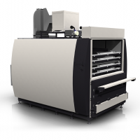
Circular, rectangular, and triangular fittings to meet aesthetics and structural performance are easily engineered. TSSA is cured in an autoclave alongside of laminated glass being processed. When the material is removed from the autoclave cycle, 100% proof testing can be completed. This quality assurance benefit is unique to TSSA as it provides immediate feedback on the structural integrity of the assembled pieces.
Conventional Structural Silicone materials have been studied for impact resistance [8] and blast mitigation [9]. Wolf et al provided data generated at the university of Stuttgart that showed increased tensile and elongation of structural silicone materials under extreme strain rates of 5m/s (197in/s) when compared to the quasi-static strain rates specified in ASTM C1135 [10] to indicate a strain dependent relationship on physical properties.
As TSSA is a highly elastic material, with higher modulus and strength compared to structural silicone, it is expected to follow the same general behavior. Although lab testing at high strain rates was not conducted, it was expected that the high strain rates in a blast would not affect the strength.
Bolted glass connections have been tested to blast mitigation standards [11] and presented at Glass Performance Days in 2013. The visual results clearly showed the advantage of mechanical retention of the glazing after glass breakage. This will be a challenge for a purely adhesively attached system.
Test Specimens: Fabrication and Quality Assurance
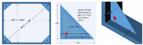
Frames were fabricated from American Standard Steel Channels of dimension 151mm deep x 48.8 mm wide x 5.08mm web thickness (6” x 1.92” x 0.20”) commonly referred to as a C 6” x 8.2# channel. The C Channels were welded together at the corners and a 9mm (0.375”) thick triangular section was welded in the corners, set back from the face of the frame. An 18mm (0.71”) hole was drilled in the plate so that a 14mm (0.55”) diameter bolt could be easily inserted into it.
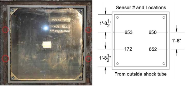
The 60mm (2.36”) diameter TSSA metal fittings were placed 50mm (2”) from each corner. Four fittings were applied to each piece of glass to make everything symmetrical. A unique feature of TSSA is the fixture can be placed close to the edge of glass. Drilled fittings into glass for mechanical retention have specific dimensions from the edge that have to be incorporated into the design and the holes must be drilled before tempering.
The close dimension to the edge enhances the transparency of the finished system while allowing reduced spider attachments as the moments on typical spiders are lower. The glass chosen for the project was two layers of 6mm (1/4”) tempered clear 1524mm x 1524mm (5’ x 5’) laminated with Sentry Glass Plus (SGP) ionomer interlayer 1.52mm (0.060”).
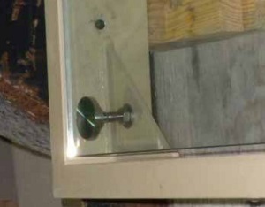
TSSA discs 1mm (0.040”) thick were applied to a primed stainless steel fittings 60mm (2.36”) in diameter. The primer is designed to enhance the adhesion durability to stainless steel and is a combination of silane and titanate in solvent. The metal discs were pressed onto the glass with a measured force of 0.7 MPa (100 psi) for one minute to provide wetout and contact. The assembly was put into an autoclave that reached 11.9 Bar (175 psi) and 133 C° (272°F) so that the TSSA would achieve a 30 minute soak time in the autoclave required for cure and adhesion.
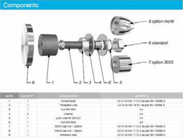
After the autoclave was finished and cooled, each TSSA fitting was inspected, and then torqued to 55Nm (40.6 ft-lb) to demonstrate a proof load of 1.3 MPa (190 psi). The fittings used for the TSSA were supplied by Sadev and identified as R1006 TSSA fittings.
The body of the fittings were assembled onto the cured pucks on the glass and the assembly was lowered into the steel frame. The nuts on the bolts were adjusted and secured so that the exterior glazing was flush with the exterior of the steel frame. The 13mm x 13mm (½” x ½”) joint about the perimeter of the glass was sealed with two part structural silicone so that testing to pressure loading could commence the next day.
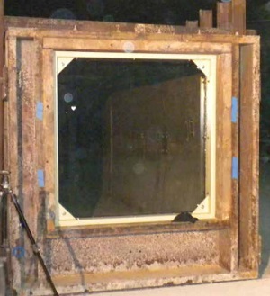
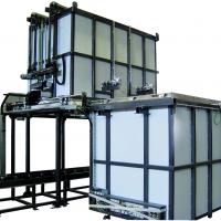
Testing was conducted utilizing a shock tube at the University of Kentucky Explosives Research Laboratory. The shock tube consists of a reinforced steel body with capability to install up to 3.7m by 3.7m units on the face.
The shock tube is driven by the use of explosives placed along the length the tube to simulate both the positive and negative phase of a blast event [12][13]. The entire glass and steel frame assembly were placed into the shock tube for testing as shown in Figure 4.
Four pressure sensors were mounted inside the shock tube so that the pressure and impulse could be accurately measured. Two digital video camcorders and a digital SLR camera were used to document the test.
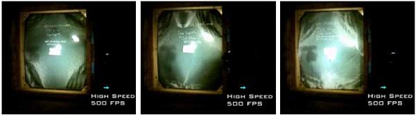
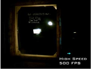
A MREL Ranger HR high speed camera located adjacent to the window outside the shock tube captured the test at 500 frames per second. A deflection laser recording at 20 kHz was set adjacent to the window to measure deflection at the center of the window.
Four frame assemblies were tested a total of nine times. If the glass did not leave the opening, the assembly was retested at a higher pressure and impulse. The target pressure and impulse is recorded along with the glass deflection data in each case. Each test was then also given a rating based on the Voluntary Guide Specifications for Blast Hazard Mitigation for Fenestration Systems, AAMA 510-14 [14].
Results and discussion
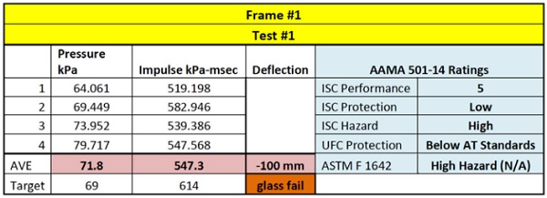
As mentioned above four frame assemblies were tested till the glass was removed from the opening from the blast. The first test was targeted to reach 69 kPa @ 614 kPa-ms (10 psi A 89 psi-msec) impulse. Under the applied load, the glazing shattered and released from the frame. The Sadev point fittings had TSSA adhered to the broken tempered glass. The glazing left the opening after it had roughly 100mm (4”) of deflection as the tempered glass shattered.
Frame 2 was tested three times with increased consecutive loading. The results showed no failures till the pressure approached 69 kPa (10 psi). Measured pressures of 44.3 kPa (6.42 psi) and 45.4 kPa (6.59) psi did not affect the integrity of the assembly. At the measured pressure of 62 kPa (9 psi) the deflection of the glass caused breakage and the glazing left the opening. All TSSA fittings had broken tempered glass attached to them as identical to Figure 7.
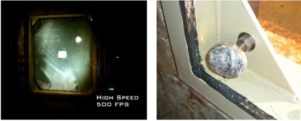
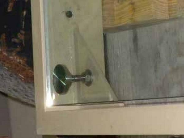
Figure 7: Glass shards adhered to the TSSA and weatherseal
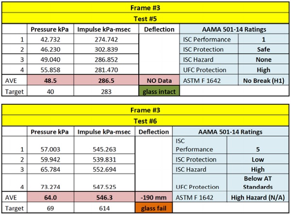
Frame 3 was tested two times with increased consecutive loading. The results showed no failure till the pressure approached the targeted 69 kPa (10 psi). Measured pressures of 48.4 kPa (7.03) psi did not affect the integrity of the assembly. A data acquisition failure did not allow deflection to be taken, however visual observations from video suggest that that Frame 2 test #3 and Frame 4 Test #7 are similar in deflection. At the measured pressure of 64 kPa (9.28 psi) the deflection of the glass measured at 190.5 mm (7.5”) caused breakage and the glazing left the opening. All TSSA fittings had broken tempered glass attached to them as identical to Figure 7.
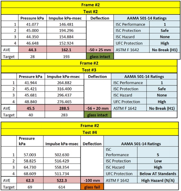
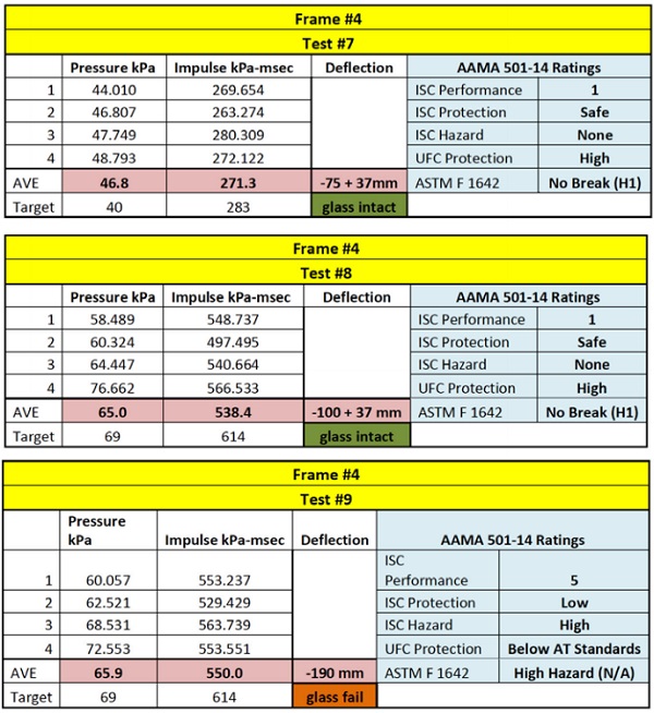
Frame 4 was tested three times with increased consecutive loading. The results showed no failure till the pressure approached the targeted 10 psi the second time. Measured pressures of 46.8 kPa (6.79) and 64.9 kPa (9.42 psi) did not affect the integrity of the assembly. The glass was measured to deflect 100mm (4”) during test #8. It was anticipated that this loading would cause the glass to break, however an additional data point was able to be taken.
During test #9, the measured pressure of 65.9 kPa (9.56 psi) deflected the glass 190.5 mm (7.5”) and caused breakage and the glazing left the opening. All TSSA fittings had broken tempered glass attached to them as identical to Figure 7. The fittings were easily removed from the steel frame without any apparent damage in all cases.
The TSSA remained intact for each test. When the glass remained intact, the there was no visual change in the TSSA after the testing concluded. The High speed video showed the glass breaking at the mid points of the span, and then leaving the opening.
From the figures 8 and 9 comparing glass failure to none, it is interesting to note that the pattern of fracture in the glass occurs in section away from the adhesive point of attachment indicating that the unbound section of glass is reaching a bending point that has rapidly approached the embrittlement yield point in the glass versus the section that are held adhesively.
This suggests that the broken plate in these sections is likely moving mostly in shear during the testing. In combination with this principle and the observation that the failure mode appears to be embrittlement in the glass thickness at the interface of the adhesive, the control of the deflection by increased glass thickness or other means should improve the performance as stated loads are increased.
Frame 4 Test #8 was a pleasant surprise at the test facility. While the nonbreaking of the glass allowed the frame to be tested again, this large load was held intact by the TSSA and the perimeter weatherseal. The design windload for this TSSA system using 4 60mm attachments supporting the glazing for both live and permanent loads is 2.5 kPa (50 psf). This is a moderate design with desirable architectural transparency that exhibited extreme loading and the TSSA remained intact.
Conclusions and Recommendations
This study was undertaken to determine if adhesive attachment of glazing systems has some sort of inherent danger or flaw in low level specified blast performance requirements. It is clearly evident that the simple system of 60mm TSSA fittings applied close to the edge of the glazing has performance up to the breakage of the glass. When glass is designed to resist breakage, TSSA is a viable method of attachment to provide a level of protection while maintaining the architectural desire for transparency and openness.
Based upon the standard, ASTM F2912-17, the window assembly tested meets a hazard level of H1 at a specification level of C1. The fittings used in the study, Sadev R1006, were unaffected.
Tempered glass used in this study was the “weak link” in the system. Once the glass broke, the TSSA and the perimeter weatherseal were unable to retain the bulk of the glazing because small shards of glass remained on the silicone materials.
From perspective of design and performance, TSSA adhesive systems have now been proven to provide a high level of protection in blast rated façade assemblies in the initial levels of blast performance specification as noted by widely accepted industry standards. The tested façade indicates a clear performance difference in hazard classification for loads between blast loads of 41.4 kPa (6 psi) and 69 kPa (10 psi).
Of importance, though, is that the difference in hazard classification is not attributed to a failure in adhesive as indicated by the cohesive mode of failure of the adhesive and glass shards between the hazard thresholds. Based on observations, properly sizing the glass to minimize deflection to prevent embrittlement due to bending and increased shear response at the interface of attachment appears to be a critical factor in performance.
Future designs may be able to incorporate reduced hazard levels at higher loadings through increased glass thickness, location of the point fixation relative to edge and increased contact diameter of the adhesive.
References
[1] ASTM F2912-17 Standard Specification for Glazing and Glazing Systems Subject to Airblast Loadings, ASTM International, West Conshohocken, PA, 2017, https://doi.org/10.1520/F2912-17
[2] Hilliard, J. R., Parise, C. J., and Peterson, C. O., Jr., Structural Sealant Glazing, Sealant Technology in Glazing Systems, ASTM STP 638, ASTM International, West Conshohocken, PA, 1977, pp. 67–99.
[3] Zarghamee, M. S., Schwartz, T. A., and Gladstone, M., “Seismic Behavior of Structural Silicone Glazing,” Science and Technology of Building Seals, Sealants, Glazing and Waterproofing, Vol. 6, ASTM STP 1286, J. C. Myers, Ed., ASTM International, West Conshohocken, PA, 1996, pp. 46–59.
[4] Carbary, L. D., A Review of the Durability and Performance of Silicone Structural Glazing Systems, Glass Performance Days, Tampere Finland, June 2007 conference proceedings pp. 190-193
[5] Schmidt, C. M., Schoenherr, W. J., Carbary L. D., and Takish, M. S., “Performance Properties of Silicone Structural Adhesives,” Science and Technology of Glazing Systems, ASTM STP1054, C. J. Parise, Ed., American Society for Testing and Materials, Philadelphia 1989, pp. 22-45
[6] Wolf, A.T, Sitte, S., Brasseur, M., J., and Carbary L. D, “Preliminary Evaluation of the Mechanical Properties and Durability of Transparent Structural Silicone Adhesive (TSSA) for Point-Fixing in Glazing” Fourth International Symposium on Durability of Building and Construction Sealants and Adhesives, Journal of ASTM International, published online August 2011, Volume 8, Issue 10 (November 2011), JAI 104084, available at www.astm.org/DIGITAL_LIBRARY/JOURNALS/JAI/PAGES/JAI104084.htm.
[7] Clift, C., Hutley, P., Carbary, L.D., Transparent Structural Silicone Adhesive, Glass Performance Days, Tampere, Finland, June 2011, conference proceedings pp. 650-653
[8] Clift, C., Carbary, L.D., Hutley, P., Kimberlain, J., “Next Generation Structural Silicone Glazing” Journal of Facade Design and Engineering 2 (2014) 137–161, DOI 10.3233/FDE-150020
[9] Kenneth Yarosh, Andreas T. Wolf, and Sigurd Sitte “Evaluation of Silicone Sealants at High Movement Rates Relevant to Bomb Mitigating Window and Curtainwall Design” Journal of ASTM International, Vol. 6, No. 2 Paper ID JAI101953
[10]ASTM C1135-15 Standard Test Method for Determining Tensile Adhesion Properties of Structural Sealants, ASTM International, West Conshohocken, PA, 2015, https://doi.org/10.1520/C1135-15
[11] Morgan, T., Advances in Explosion Resistant Bolt Fixed Glazing, Glass Performance Days, June 2103, Conference proceedings pp 181-182
[12] ASTM F1642/F1642M-17 Standard Test Method for Glazing and Glazing Systems Subject to Airblast Loadings, ASTM International, West Conshohocken, PA, 2017, https://doi.org/10.1520/F1642_F1642M-17
[13] Wedding, William Chad, and Braden T. Lusk. “Novel method to determine blast resistant glazing system response to explosive loading.” Measurement 45.6 (2012): 1471-1479.
[14] “Voluntary Guide Specification for Blast Hazard Mitigation for Vertical Fenestration Systems” AAMA 510-14.