
Authors: Chiara Bedon and Maria Vittoria Santi
Academic Editor: Francesco Zammori
Source: Mathematical Problems in Engineering, vol. 2022, Article ID 6059466, 20 pages, 2022, Hindawi
DOI: https://doi.org/10.1155/2022/6059466
Abstract
Bird-strike analysis is of particular relevance for aircraft engineering applications, where major wing or fuselage components may suffer for possible collision during flying stage and result in serious structural damage. To this aim, the Federal Aviation Regulations requires dedicated bird-strike resistance assessment tests and certifications. In building applications, glass is also largely used for vertical and horizontal load-bearing components. In such a kind of structural design context, major attention is given to wind pressure, seismic loads, impact due to crowd and human body (i.e., to prevent falling out), or even explosions, and rather null consideration is posed for bird-strike analysis, due to their expected limited impact forces and effects on glass.
This paper investigates such a topic giving evidence of the dynamic response of an existing glass facade built in 60 s as a part of a museum in Italy. The vulnerability analysis is carried out with computationally efficient Finite Element (FE) numerical models of consolidated use for bird-strike, based also on preliminary mechanical characterization from in-field geometrical inspection and Operational Modal Analysis (OMA) experiments. Local and global dynamic effects due to localized bird-strike on the examined glass facade are discussed based on parametric numerical analysis from Coupled Eulerian Lagrangian (CEL) method.
1. Introduction
Bird-strike analysis and damage prediction is of particular relevance for aircraft engineering application, where major wing components of fuselage components may suffer for possible collision from birds during flying stage and result in serious structural damage for aircraft components. To this aim, the Federal Aviation Regulations (FAR) provides reference performance indicators for forwards facing components and require dedicated bird-strike resistance assessment (usually based on certification tests). In the years, research studies have been focused on assessment and development of efficient and reliable Finite Element (FE) numerical approaches that could be used to support or replace experiments, and several approaches have been taken into account for specific applications in aircraft design and technologies [1–4]. Among exiting studies, the vulnerability of aircraft components to this type of high-speed soft-body impact was pointed out.
In building applications, glass is also largely used for vertical and horizontal load-bearing components [5]. Especially for facade applications, several technical documents and guidelines are nowadays available to support designers in preventing possible damage and failure of glass panels under ordinary design actions and even impact [6]. In such a kind of structural design context for buildings, major attention of research investigations on glass facades and envelopes is given to the analysis, retrofit and/or mitigation of maximum effects due to wind action [7–9], seismic loads [10–14], impact due to crowd/human bodies [15–20] (where the potential risk of falling out of building occupants should be prevented), or even explosions [21–24] and multi-hazard [25], and rather null consideration is proposed for the bird-strike analysis, being often associated to negligible/limited impact forces and effects on glass components. While this is true for most of modern and newly designed structural glass applications, in which specific calculation approaches are taken into account against conventional ordinary actions and accidental events for buildings, careful consideration should be paid for existing and even historic glass components, which were not specifically conceived to offer any kind of load-bearing capacity, but only realized in the form of non-structural components.
In this paper, the attention is given to a glass facade built in 1962 and currently subjected to accidental bird-strike. The vulnerability analysis is carried out with the support of computationally efficient FE numerical models carried out in ABAQUS/Explicit [26] and representative of consolidated literature use for bird-strike investigations. In doing so, careful attention is given also to the structural model characterization, based on in-field geometrical inspection and Operational Modal Analysis (OMA) experiments, in support of the dynamic identification of structural/mechanical features.
As shown, differing from aeronautic applications, relevant aspects are represented by variation in structural and mechanical features of target systems (i.e., airplane components vs. facade components) but also variation in impact features (i.e., low impact velocity for buildings in place of reference values of ≈150–300 m/s for airplane applications). The study proves that even minor birds-strike events can involve high stress peaks in similar glass systems, and thus attention may be required to prevent the potential failure. Furthermore, the analysis shows the local and global dynamic effects of a relatively localized strike on facades which should be analyzed in the form of composite systems rather than the individual glass components.
2. Bird-Strike Effects and Damage Analysis
Bird-strike experiments and numerical simulations are of particular interest especially for aerospace engineering applications, where aircraft components must be specifically designed to resist accidental, high-speed soft-body impacts from birds. Experimental studies against different structural components can be found, for example, in [27, 28].
Numerical simulations, in this context, can provide efficient support to design, and prevent complex experimental protocols. At the same time, however, careful attention must be paid for description and characterization of model components, as well as impactor features [2, 3, 29]. Actually, maximum effects can be predicted based on efficient analytical models [30], or numerical approaches according to (unpractical) Lagrangian description of birds [31], or to the meshless Smooth Particle Hydrodynamic (SPH) approach [32–34] or even to the mesh-dependent, fixed boundary Coupled Eulerian–Lagrangian (CEL) approach [35, 36]. A promisingly efficient alternative approach to the classical CEL method is represented by the movable Eulerian domain option available in ABAQUS/Explicit [37], in which the Eulerian volume is not fixed in space but can move and allow a strong reduction in the mesh refinement.
With a specific focus on glass for building applications, studies of literature have been dedicated in the years to the load-bearing performance assessment of various systems and components under hard-body or soft-body impact, by taking advantage of laboratory experiments and/or numerical simulations [15–20]. For facade systems and components, this is in line with design regulations and technical recommendations (like for example EN 12600 standard, DIN 18008-4 Annex A document, CWCT TN 76) that are used to prevent falling out of building occupants (in case of glass breakage), see [18]. A common aspect of literature studies is that laminated glass (LG, with minimum two glass layers) was taken into account for most of the structural applications. At the same time, impact conditions were characterized by standardized setup configurations from standards. Accordingly, the impactor consisted of a conventional twin-tyre or a spheroconical bag (with a total mass of M = 50 kg each), see Figure 1. In these conditions, the impact dynamic of a given glass system is commonly quantified and assessed in terms of input impact energy Eimp, based on mass M and impact velocity v of the impactor:
![]()
and specific performance indicators for the glass system to verify, under impact configurations with up to Eimp = 800 J of impact energy and various impact points on glass [38, 39].
![Figure 1 Conventional impactors for the vulnerability analysis and certification of glass facades: (a) twin-tyre and (b) spheroconical bag. Figures reproduced from [18] under the terms and permission of CC-BY license agreement.](/sites/default/files/inline-images/Fig1_310.jpg)
In the present study, historic glass facades (which have not been specifically designed to resist against possible impact) are taken into account. The attention is focused on the vulnerability assessment of bird-strikes, by taking inspiration from an in-service glass system realized in Italy. Differing from conventional impactors for the certification and assessment of glass facades (i.e., Figure 1), birds have a relatively small mass and specific mechanical properties which should be taken into account for the calculation purposes. According to literature, the classical CEL numerical approach is used to assess the vulnerability of the system under realistic accidental scenarios.
3. Examined Full-Size Steel-Glass System
3.1. Geometrical Properties
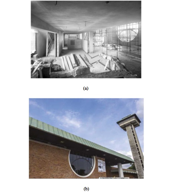
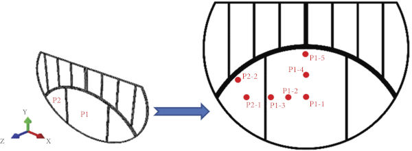
The structural system object of study consists of a steel-glass assembly designed in 1961 and built in 1962, as a composition of glass panes and a grid of steel mullions and arched transoms (Figure 2(a)). The particular aspect of this structural system is presented by its shape (circle-based facade concept) and by its size (overall included in a rectangular shape of approximately 7 m in width and 5 m in height, see Figure 2(b)), compared to the thickness and load-bearing capacity of single components. Glass elements are in fact shaped to follow the overall circle path of the facade, and are characterized by simple monolithic (and relatively small) total thickness, compared to the covered surface. Moreover, steel members are reduced to a minimum, in order to preserve the transparency of the facade. The examined system belongs to the so-called Information and Documentation Centre (CID) museum, which is located in Torviscosa (Udine), see Figure 3 and [40].
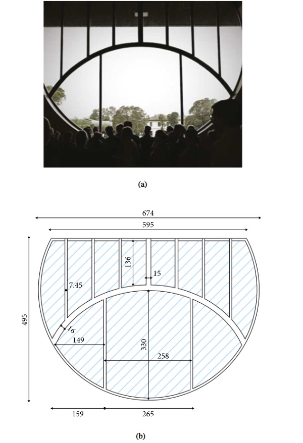
3.2. Mechanical Boundaries
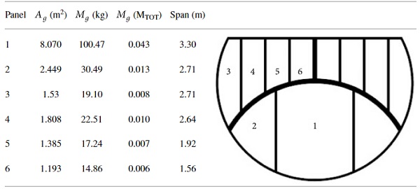
For the purpose of present investigation, a preliminary in-field diagnostic analysis was performed to verify the state-of-art condition of facade elements, namely, the glass panels, the steel members, and the bonding layers between glass and steel components. The preliminary assessment was further exploited with a geometrical inspection, to measure the actual size of panels and bracing components. The geometrical characterization of the examined facade is summarized in Figure 2(b). The maximum size of central glass panel was measured in 3.3 meters in height by 2.58 meters in width. The mass of steel and glass members was calculated in approximately MTOT = 2358 kg, where the total sum of glass elements was estimated in ≈0.13 MTOT (≈309 kg). A list of properties for all the glass components is reported in Table 1.
Table 1 Summary of glass components features (labels as for indoor view).
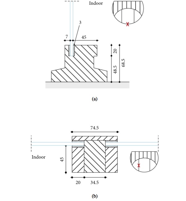
From the visual analysis, see Figure 4, it was also noted a rather linearly clamped boundary condition for all the glass plates. The clamp condition was achieved, at the time of construction, by means of solid steel members that were screwed together to realize mullions and transoms for the metal frame. The central member of each mullion or arched transoms was then rigidly assembled with adjacent or intercepting members, to compose the frame grid. At the same time, two additional solid steel members were connected by screws to the central element, to create a thin gap (≈10 mm) for positioning and restraining the glass plates in between. A silicon infill (3 mm in thickness) was in fact used to linearly bond the glass and steel elements. The thickness of annealed glass panels (5 mm) was finally confirmed by in-field OMA vibration experiments and dynamic identification of structural parameters (see Section 5).
3.3. Operational Conditions
The CID museum (and the glass-steel facade on the Southern side of building) is subjected to environmental and human-made design actions since their original construction. For the glass system, various sources of vibration can be detected in normal operational condition. The building is in fact very close to an active industrial plant and to daily heavy-traffic of trucks and cars. Moreover, a railway track (Trieste-Venezia rail network) runs in parallel to the building, at a distance of few meters only. Finally, the glass facade is the object of wind loading and gusts, and even rather frequent accidental strikes by birds (Figure 5), which suggested the need of additional detailed investigations.
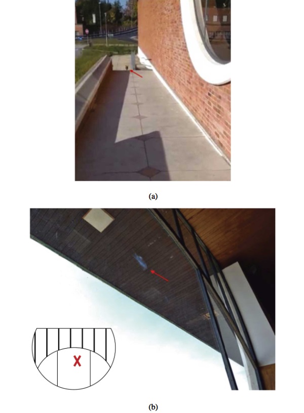
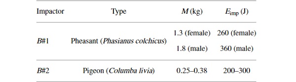
Typical accidental events for the facade under investigation are characterized by the strike of common pheasants (Phasianus colchicus) like in Figure 6(a) or pigeons (Columba livia) as in Figure 6(b). The first type of soft-body impactor (“B#1”, in the following) is characterized by average mass M1 = 1.3 kg (for females, and up to 1.8 kg for males), with a maximum flying speed v1, max = 20 m/s [41]. The second impactor type, “B#2,” is characterized by relatively small size, with M2 = 0.25–0.38 kg, and v2, max = 40 m/s the maximum speed [42]. According to equation (1), the examined facade is hence potentially subjected to impact conditions as summarized in Table 2 (limit values). In the present study, the attention was primarily focused on B#1 impactor with 1.3 kg of mass and B#2 with 0.38 kg of mass, based also on in-field observations (i.e., Figure 5).
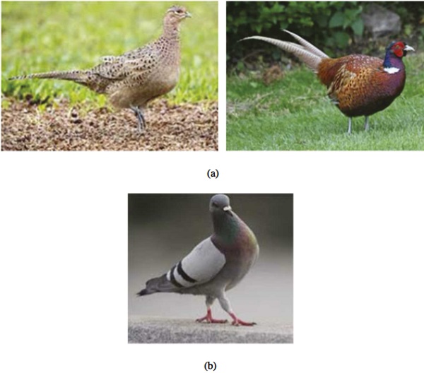
Table 2 Summary of bird-strike impact features for the present study, with maximum expected impact energy (based on equation (1)).
3.4. Reference Glass Strength
The examined facade system is characterized by the use of annealed monolithic glass panels (5 mm in thickness) which were not conceived, at the time of design and construction, to offer specific load-bearing capacity against accidental events. Actually, such a condition is a major issue for safety purposes, given that annealed monolithic glass is not able to provide appropriate safety levels as LG [5, 43].
Existing regulations and design standards require in fact that any kind of accidental condition should be properly checked in terms of stress peaks and resistance, as well as deformation limits and post-failure residual capacity [43]. Especially in terms of resistance verification, impact events represent a critical condition for monolithic glass panels, given that they cannot take advantage from bonding interlayers and their additional plasticity and dissipation. Actually, the design tensile strength of annealed float glass under conventional loads should be in fact calculated as [43]:

with fg; k = 45 MPa; kmod depending on the loading time (1 for instantaneous loads); RM = 1 for second-class annealed glass; γM = 2.5 for annealed glass. Following [43], when the resistance check is carried out at a distance d from glass edges which is at least equal (or higher) than 5 s (with s the thickness of glass), it is assumed that ked = 1 and λgl = 1. Further, ksf = 1 for float glass. Finally, λgA is comprised between 0.75 and 1, to account for the area of glass under maximum stress and the statistically higher probability of the presence of defects in glass.
The resistance check is verified when the given design action results in maximum stresses (due to the i-th magnified design action Ed, inclusive of partial safety factor) up to:
![]()
For exceptional design loads, technical documents like [43] also require that “in order to determine loads caused by exceptional actions such as fire, impacts and explosions, reference may be made to the indications contained in national technical standards.”
For specific investigations of glass under impact and impulsive actions, the Dynamic Increase Factor (DIF) can be accounted to replace the quasi-static characteristic material strength (see also Figure 7and [6, 44]), thus the limit condition to satisfy (with design actions Ed at their characteristic value) is given by:
![]()
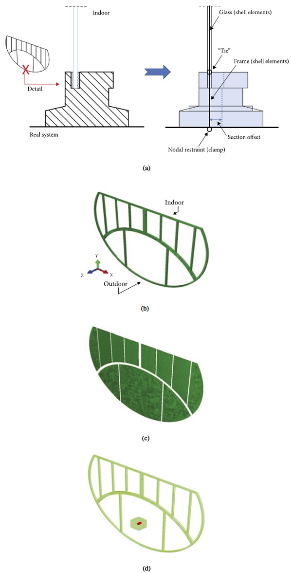
Monolithic shell sections (S4R type) lying on the same xy plane were used also for glass panels (Figure 8(c)), while the surface-to-surface “tie” continuous constraint was introduced along the edges glass panes. The free bending span for glass panels was hence set to coincide with their exposed surface, while the 20 mm deep region of glass embedded in the frame was simplified with an ideal rigid clamp. Rigid nodal boundaries for translational (ux = 0, uy = 0, uz = 0) and rotational (rx = 0, ry = 0, rz = 0) components were finally assigned to the perimetral edges of frame elements, in order to reproduce mechanical fixings of circle-based metal structure to the concrete background. Such a FE structural model was used for various bird-strike simulations as in Figure 8(d). In doing so, the mesh size and pattern were calibrated based on a preliminary sensitivity study. The final edge size of 4-node based elements resulted in an average of 0.03 m (0.01 m the minimum and 0.06 m the maximum), for a total of ≈21,000 shell elements and ≈136,000 DOFs (Figure 8). For the purpose of present study, through the bird-strike parametric analysis, structural damping was disregarded as usual for glass systems under impact or impulsive events, because characterized by negligible variation of maximum effects due to the imposed mechanical loads [15, 18, 19, 47, 48].
The mechanical characterization of materials was based on literature efforts, thus an idealized elastic-plastic constitutive law was used for steel (Es = 210 GPa the Young’ modulus, νs = 0.3 the Poisson’ ratio, ρs = 7800 kg/m3 its density, with yielding σy, s = 235 MPa), and strain rate effects were disregarded.
The “brittle cracking” material option, based on a Rankine damage model, was taken into account for glass. In particular, input parameters were set in Eg = 70 GPa, νg = 0.23, ρg = 2490 kg/m3 [43, 49]. Regarding the damage evolution and propagation in tension, the fracture energy Gf = 3 J/m2 was assumed from [50, 51] with relevant input material properties to account for possible glass fracture (“brittle shear” and “brittle failure” sub-options), while the tensile strength in bending was set equal to fg: k = 45 MPa [43, 49] as for annealed glass under quasi-static loads (Section 3.4). Studies of literature on the DIF trend for the tensile strength under impact, and in general as a function of strain rate, suggest in fact a rather limited increase for the range of strain rate which was object of present investigation [6, 44]. A quantitative comparison in support of this assumption is also reported in Figure 7, where the DIF for tensile strength is reported from literature experiments, as a function of the imposed strain rate. These literature values are compared with the average and maximum strain rate calculated for the present study (as obtained in the post-processing stage of FE numerical results).
4. Numerical Investigation
4.1. Model Assembly
The herein presented numerical study was carried out in ABAQUS/Explicit [26], by taking advantage of the consolidated CEL modelling approach. Studies of literature proved that the latter is able to support more accurately the simulation of fluid-like bird behaviour for impact scenarios and to improve the analysis stability [45, 46]. More precisely, Eulerian mesh was used to describe birds like soft-body impactors, while the structural system object of analysis was discretized by traditional Lagrangian FE formulation. In this manner, impact forces involved in the fluid-structure interaction problem were efficiently transferred to the target structural components (for the analysis of traditional performance indicators) based on Eulerian–Lagrangian, penalty-based contact algorithm. In addition, the movable Eulerian mesh option was used to preserve the high computational costs.
4.2. Structural Model
The structural model was developed through various procedural steps, so as to optimize its accuracy and computational cost. At first, solid brick elements were used in preliminary analysis for frame components, with actual geometrical features as in Figure 4. After vibration frequency and static bending setup assessment, the final FE assembly was optimized and resulted composed of homogeneous shell elements (S4R type) able to reproduce the geometrical features schematized in Figure 2(b) for both glass and steel components. The schematic detail of discretization is proposed in Figure 8(a). For the frame members with cross section as in Figure 8(a), a set of full solid sections made of homogeneous shell elements (S4R type) with thickness offset was in fact used. The set of shell elements was designed with middle axis on the xy global coordinate system of the FE assembly, see Figure 8(b).
![Figure 8 Expected DIF trend for tensile strength of glass, as a function of the imposed strain rate, based on literature studies, and evidence of current range of interest for the FE parametric study (ABAQUS/explicit). Figure adapted from [6].](/sites/default/files/inline-images/Fig8_207.jpg)
4.3. CEL Bird Model
According to several literature studies, a cylindrical volume with hemispherical ends like in Figure 9(a) was taken into account. The cylinder was derived as a scaled shaped from the conventional size in Figure 9(a), where the reported dimensions are valid for 1.81 kg bird (FAR 25 bird-strike requirements for ‘‘Damage-tolerance and fatigue evaluation of structure” in aircrafts [45, 52]). In doing so, the length to radius ratio was kept fix in 2 : 1, and the reference diameter D for B#1 and B2# impactor types was defined as:

with M the total mass of the impacting bird and ρ its density.
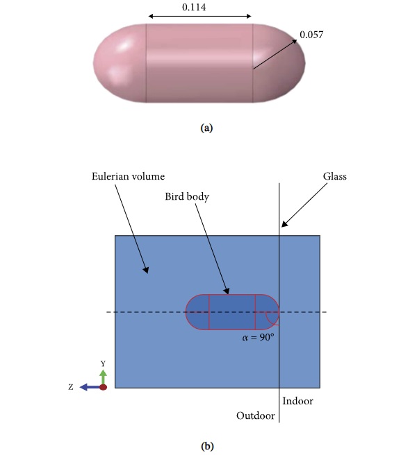
To reproduce various strike configurations of technical interest for the presently investigated glass-steel facade, the cylindrical volume was assumed to hit the glass facade perpendicularly, as in Figure 9(b), thus the impact angle α = 90° was kept fix. Moreover, the target glass surface for bird body impact was always kept to coincide with the outdoor side of facade, as in reality. For each one of the examined strike conditions, an initial translational velocity (with imposed velocity vector parallel to z axis of FE assembly) was assigned to CEL instance (Figure 9(b)), and the impact effect on the facade was investigated with the support of interposed general penalty-based contact algorithm of ABAQUS/Explicit library.
For each impact configuration, bird material was replaced with an equivalent volume of water, given that birds mostly consist of water and air trapped in the bones and lunges [45]. To this aim, as usual for CEL approach, a cubic volume of Eulerian elements (EC3D8R type) was created to embed the bird instance (Figure 9(b)). The volume (0.5 × 0.5 × 0.5 m3) and grid size for Eulerian elements was set to avoid the loss of the embedded CEL bird body after impact and in the dynamic stage of simulation. A total of 100,000 elements was used for discretization. Moreover, calibrated water parameters for material characterization were taken from [45, 46]. The most important aspect in such a kind of hydrodynamic problems is that the material’s volumetric strength and pressure are sensitive to the density ratio. The pressure to density relation is given by:
where ρ0 is the reference material density, Γ0 and sf are material constants, c0 is the speed of sound in the material, and Em is the internal energy per unit of mass, while = (1 − ρ0/ρ) represents the nominal volumetric compressive strain, with ρ the current material density. In the present study, to include hydrodynamic material effects for bird body under impact, the Mie–Gruneisen (Us–Up) equation of state (EOS) from ABAQUS library was used. The four required input parameters for Us-Up EOS, that is the linearly reduced Hugoniot form of equation (6), were set as proposed in [2, 45, 52–54], with c0 = 1480 m/s, sf = 0, and Γ0 = 0. Finally, the material density was set in ρ0 = 938 kg/m3. Dynamic Newtonian viscosity was also considered for water, and set equal to 0.001 Ns/m2 [55].
5. Structural Model Validation
The structural model validation was carried out by taking advantage from post processing of experimental output from on-site OMA-based vibration measurements, and in particular in terms of vibration modes detection and corresponding vibration frequencies for the steel-glass system. Dynamic identification techniques of typical use for structural health monitoring were applied to the glass-steel facade to derive basic dynamic parameters, as also in accordance with the previous studies on glass systems [47, 56].
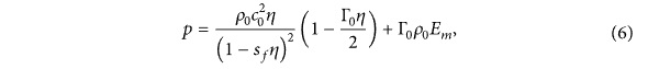
Two different MEMS sensors were used simultaneously for the facade under nondestructive random excitation. To minimize the influence of instruments and setup on the vibration performance of such slender glass components, mini devices were used (Figure 10(a)), as obtained based on IMU AHRS MPU6050 chip board, wireless, three-axes accelerometer sensor (±16 g its range, 0.005 g the resolution, and 0.2–200 Hz the available sampling rate). The size of each sensor was measured in 36 × 36 mm, with 15 mm the thickness and 20 grams the weight. According to size and mass parameters reported in Table 1 for glass panels, the actual dimensions and weight of a typical MEMS sensor was assumed to have negligible effects on structural dynamic aspects (i.e., up to ≈5000 the ratio of panel P1 weight compared to sensor).
For all the OMA configurations, the sensors were installed on the indoor side of the facade. More precisely, see Figure 10(b), one of MEMS sensors was kept fix at the midspan section of mullion as in the schematic drawing of Figure 10(b), while the second MEMS sensor was fixed to at the centre of glass panel characterized by maximum size (P1, based on Table 1). Figure 10(c) shows a detail of (x′, y′, z′) local reference system for acquisitions from MEMS sensors, as compared to the global coordinate system in use for the FE assembly. During the experiments, the sampling rate was set on 200 Hz and several records were collected under ambient excitation (i.e., trucks) and random finger hits.
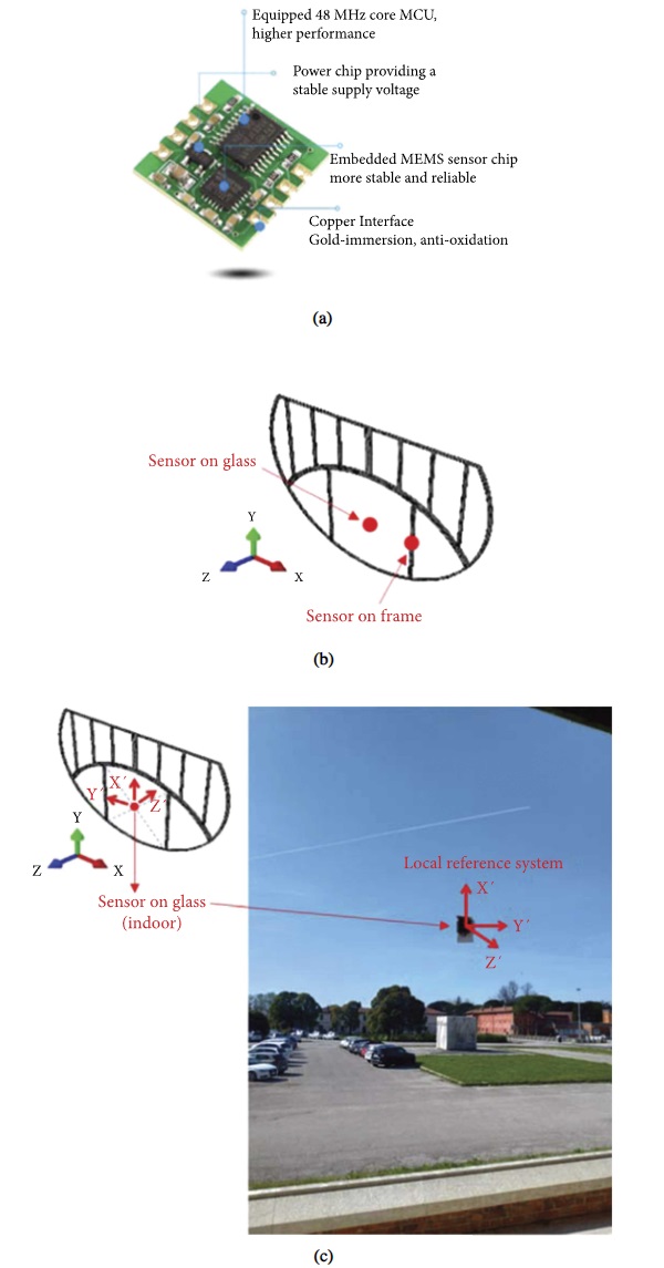
In terms of vibration performance of the system, Figure 11(a) reports the out-of-plane acceleration at the centre of panel P1, when subjected to OMA testing with finger impact. As far as these accelerations are compared with records at the midspan section of steel mullions (as in the schematic drawing of Figure 6(b)), there is evidence in Figure 11(a) of a load transfer effect, from P1 glass panel (directly exposed to impact) to the frame, and then to the other glass components of the facade. This results in rather global vibration performance of the system as a whole.
In this regard, for the post-processing analysis of experimental records and for the derivation of experimental vibration frequencies of the system, a major support was taken from modal analysis carried out in ABAQUS/Standard for the structural system characterized as in Section 4.2.
The resulting frequency response is schematized in Figure 11(b), with evidence of experimental and numerical vibration frequencies, while Figure 11(c) shows the modal shapes of low vibration modes. As shown, the overall dynamic response is governed in its 1st vibration mode by bending deformation of panel P1, being rather flexible compared to the other structural members. Also, the 2nd and 3rd third numerical vibration modes in Figure 11 are affected by the bending response of panel P1 only. A composite bending response of the facade as a whole can be found only for the 4th mode, or higher.
It is worth to note in Figure 11(b) the generally good correlation of experimentally and numerically predicted vibration frequencies of the structure, thus confirming the validity of the structural mode for impact analyses.
6. Parametric Numerical Analysis and Discussion of Results
Through the numerical investigation, the attention was focused on the parametric analysis in ABAQUS/Explicit of maximum effects due to various impact configurations of interest for the case-study building system. Major attention was given to the local and global structural response of the facade when subjected to various strikes characterized by different impact point, or bird speed and mass, as well as to the efficiency assessment of possible retrofit interventions.
Overall, the impact and control points were defined as in Figure 12. In particular:
(i) P1-1 and P2-1 were set in the centre of panels P1 and P2, respectively,
(ii) P1-3, P1-5 (for P1) and P2-2 (for P2) were set at the midsection of glass edges (with a distance of 10 s = 50 mm from edges),
(iii) P1-2 and P1-4, finally, were interposed in the middle of the previously defined control points.
6.1. Impact Point
Bird collisions on glass panels for aeronautic applications (like for example aircraft cockpit windows) are generally assessed in terms of stress and strain evolution in the target region, including pressurization effects [30]. Maximum effects on structural components are achieved in a rather short time interval, typically in the order of few milliseconds, and during this interval the target system is required to accommodate the input energy. As far as the bird-strike induced, the impact performance of glass components for constructional applications is addressed as in present study, technical documents and standards for structural design require to verify that the strength capacity of the system is appropriate for safety purposes, and thus the tensile stress evolution in glass represents a primary indicator of interest [18]. Additional attention may be required by out-of-plane deflection (and/or velocity) of glass panels (compared to allowable deflection amplitudes), but also by the stress evolution in gaskets and bonds (to prevent failure), and even by reaction forces that the glass system/facade transfers to the primary building (to design the robust connections).
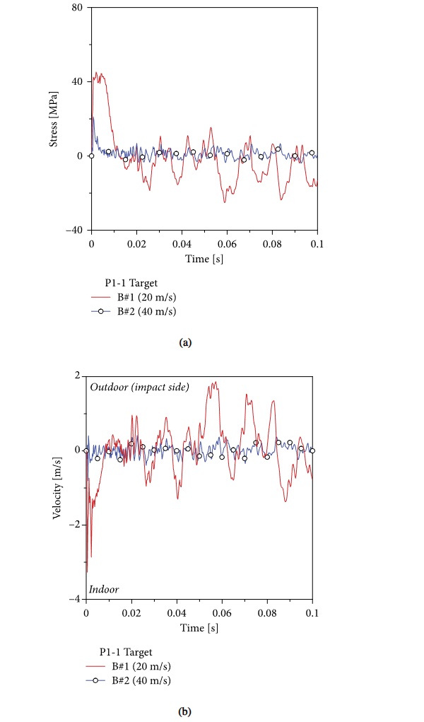
For the presently investigated facade under B#1 impactor at an imposed velocity of 20 m/s, for example, the effect of strike was generally quantified as in charts of Figure 13, with maximum principal stress peaks up to 42 MPa at the centre of glass (P1-1 target) and still relatively high (36 MPa) for P1-2 and P1-4. At the same time, however, the resistance verification of metal frame members was disregarded, due to their typical elastic response and relatively small stress peaks (compared to material yielding strength) that were recorded through the parametric study.
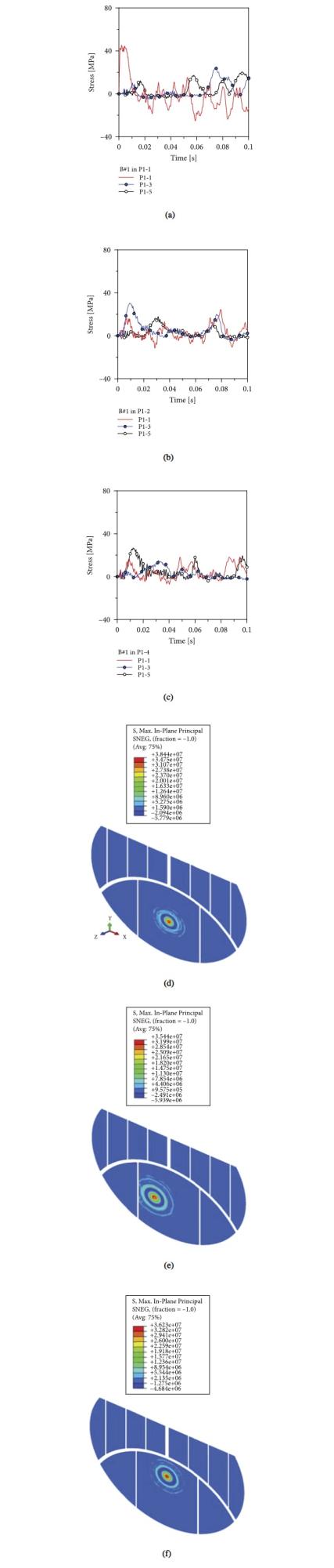
Overall, stress peaks in the central region of glass were quantified in around ≈90–95% the characteristic tensile resistance for annealed glass, that is (d > 5 s):
![]()
with DIF = 1 in the present study, which confirms the vulnerability of similar systems to accidental bird-strikes. According to equation (7) for the control points in the central part of glass panels (d > 5 s in equation (2)), even more attention should be paid for control points close to glass edges (i.e., P1-3 and P1-5 in Figure 13), due to the local effect of stiff frame members and to the limited material strength. Especially for d < 5 s, equation (2) and existing technical rules suggest in fact that ked ⟶ 0.7 (for annealed glass); λGA ⟶ 0.75; λgl < 1 (depending on size of glass and load pattern), thus reducing down to ≈−50% the reference strength value for glass and requiring careful consideration against the possible fracture.
It is also worth of interest that the comparative results in Figure 13 confirm the localization of maximum effects due to strike in a limited portion of glass (i.e., target region), with relatively smaller stress peaks in the other regions of facade. On the other side, the local dynamic response of the system should be addressed with attention also to the global behaviour of the façade as a whole, with the detailed analysis of minor dynamic effects which are transferred to unexposed glass panels and frame members. Such a finding can be observed in terms of stress evolution on control points in Figure 13 that are not exposed to the direct impact.
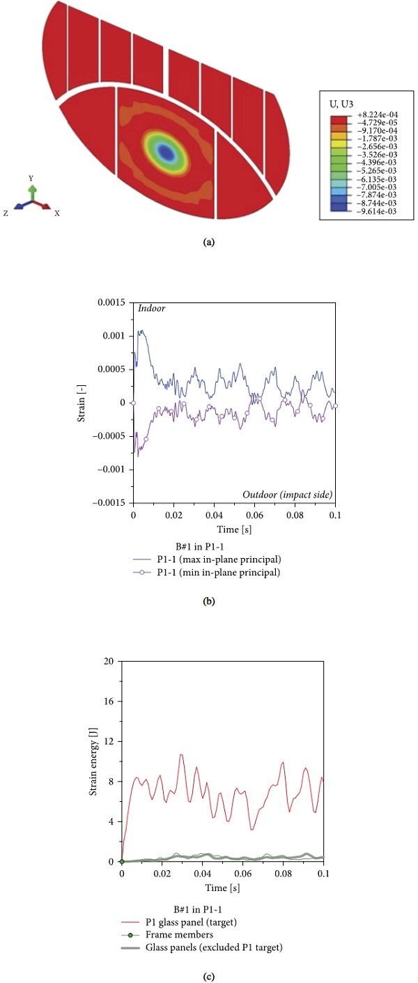
While the whole facade was involved in the global dynamic behaviour under impact, limited out-of-plane deflections were also measured for the target glass panels. A selected example is reported in Figure 14(a) for P1 panel (P1-1 target). Under bending, maximum displacements along the z global axis were generally estimated in the range of ≈8 mm maximum for the target region (i.e., ≈1/450 the bending span), which is not relevant for structural verification purposes. Moreover, a mostly symmetrical response was observed for the monolithic glass sections under impact, as also highlighted by the measurement of in-plane strain values in Figure 14(b). On the indoor side, it must be noted that positive strain values are associated to tensile stress peaks for glass as in Figure 13(a), and thus possible glass fracture with potential inward glass fragments and consequent risk for people. In this context, the analysis of energy contributions for the facade under bird-strike resulted in a major strain energy term stored by glass components directly affected by impact (P1 panel, in the present example), and rather null energy terms for the frame or for the remaining glass panels (Figure 14(c)), which is in line with rather small/negligible stress and strain peaks in the facade components not subjected to strike.
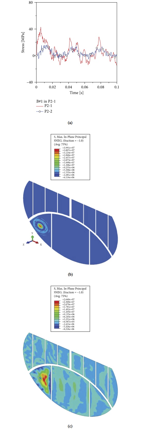
Finally, careful attention should be paid for geometrical and mechanical aspects and their effect on bird-strike assessment. In Figure 15(a), for example, the strike-induced response for P2-1 target point is shown in terms of stress evolution in glass. Tensile peaks in P2-1 were found again in the order of ≈95% the reference material strength, while stress peaks at the round-shaped glass edges (P2-2 control point) were estimated in less than half. The contour plots in Figure 15(b), in this regard, present a clear picture of the facade response in the first instant after impact. As far as the facade oscillates due to strike, see Figure 15(c), it is worth to note the stress propagation to all the other glass components (and steel frame members). On the other side, due to the robust solid section of steel members, rather small stress peaks in steel frame were generally measured, with a markedly linear elastic response of mullions and transoms.
6.2. Impactor Size and Velocity
For the facade under B#2 impact (v = 40 m/s the imposed impact speed), a qualitative dynamic response in close correlation with B#1 setup was observed. The effect of reduced mass and size of impactor, but relatively higher impact velocity, can be quantified as in Figure 16(a), in terms of tensile stress evolution in the target region. It is worth to note that also the trend of out-of-plane velocity in the target region (Figure 16(b)), which is also in line with the qualitative observations. The small impactor B#2, as shown, is associated to a reduced velocity peak on the target panel and also to a relatively small impulse duration, compared to B#1. Due to soft-body nature of birds, it is also of interest to note that the measured velocity peaks in elastic bending stage for the presently investigated system (≈2 m/s in the target region) are significantly higher than the maximum velocity peaks (≈0.75–1 m/s in the target region) which have been experimentally obtained at collapse for traditional, 3 mm thick monolithic glass windows built in 60 s and subjected to hard-body (steel ball) impact [16].
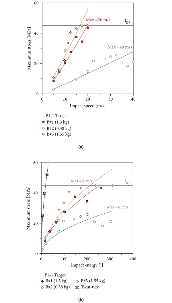
For structural capacity assessment under various accidental scenarios, tensile stress peaks in glass were thus found the primary performance indicator of interest for diagnostics. In this regard, a parametric analysis was carried out on the examined system under a multitude of impact conditions. The previously defined impactors B#1 (1.3 kg) and B#2 (0.38 kg) were taken into account. Furthermore, the impact analysis was carried out under strike of an additional bird type (B#3), characterized by total mass of 1.55 kg (average from Table 2), and of a traditional twin-tyre (as in Figure 1).
Figure 17(a) shows the maximum stress peaks in P1-1 for the target P1 panel under the effects of various impact configurations. The reference material strength (with DIF = 1) is also highlighted, giving evidence of vulnerability of the examined system. As far as the input impact energy from equation (1) is taken into account, typical trends of stress peaks in glass can be seen in Figure 17(b). It is thus worth to note the quantitative comparison and behaviour of the facade under bird-strike or conventional twin-tyre impact (as it would be required for glass systems able to prevent occupants falling out). Due to the relatively high mass of conventional twin-tyre impactor for facade testing and certification, it is possible to note that a relatively small impact velocity (and thus impact energy from equation (1)) is required to achieve critical stresses and failure in glass. For the present study, birds with mass larger than ≈1.5 kg and average speed larger than ≈15 m/s would result in the collapse of glass panels. For similar systems under small-medium size of birds, on the other side, it can be seen that the achieved maximum stresses do not affect the structural stability and integrity of glass components.
6.3. Passive Bird-Strike Mitigation
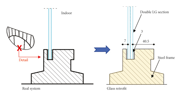
In order to minimize the effects of such a kind of accidental soft-body impact on the historic system, a possible benefit could be derived from the replacement of monolithic glass panels with double LG sections [43]. For the present study, the original s = 5 mm thick monolithic glass plates were numerically replaced by double LG sections with minimum thickness for load-bearing applications (i.e., s = 9.52 mm in total, as obtained from bonding 4 mm thick glass layer and 1.52 mm thick PVB interlayer). Figure 18 presents a schematic detail of retrofit. For the present study, moreover, the joint size (20 mm in width and 3 mm in thickness) was kept fix as in the original configuration, so as to minimize the modifications on frame components and overall layout of the facade.
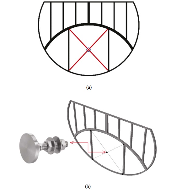
Alternatively, removal and retrofit of original glass components may be ensured by external bracing systems, like for example a set of steel cables and undrilled mechanical point-fixings able to work for contact interactions only. In this sense, the attention was focused on the “Cable X” solution in Figure 19(a), while the example in Figure 19(b) shows a possible mechanical detail which does not require glass drilling [56]. The use of external bracing cables can avoid removal of historical components, but also minimize the aesthetic impact on the assembly.
In terms of performance analysis and comparative discussion of results, the use of double LG sections to replace the existing panels can allow increasing the resisting section of glass, and thus ideally minimizing the expected stress peaks in the façade components. Besides, the total mass of glass would be mostly doubled compared to Table 1 (≈541 kg of glass in place of ≈308 kg, that is +75% the current system). Modification of mass and bending stiffness for glass components would also affect the overall dynamic response of the facade.
Most importantly, the LG capacity in bending is strictly related to the mechanical efficiency of bonding interlayers, and to their sensitivity to ambient conditions, temperature, humidity, and time [41].
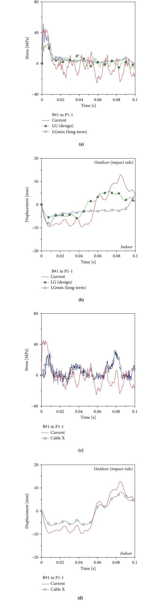
In Figure 20, in this sense, the stress analysis of current facade situation is compared with possible LG section retrofit. The attention is given to a LG section in “design” conditions, thus a rather efficient shear connection of interlayer (“LG (design)” plot), or to the same composite section after degradation of bonding interlayer (“LGmin (long-term)” plot), as it can be expected under high temperature or long-term period. As shown, stress peaks in P1-1 (Figure 20(a)) and maximum out-of-plane deflections (Figure 20(b)) can be minimized under bird-strike, by taking advantage of “LG (design)” retrofit. However, the effect of interlayer degradation on LG stresses and deformations is still predominant on the global beneficial effect of this kind of retrofit intervention.
As a result, the “LG (long-term)” response is mostly coincident with the current situation. Assuming that reversible retrofit interventions with minimum aesthetic impact should be possibly preferred especially for historic systems, Figures 20(c) and 20(d) summarize the façade response with “Cable X” mitigation system. It is worth to note that the examined configurations are representative of possible intervention examples that should be further optimized in terms of size and detailing. Besides, the comparative analysis allows to address and quantify the potential benefits of mitigation options. As it can be seen from Figure 20(c), maximum stress peaks under the most critical impact condition (P1-1) can be in fact efficiently preserved for the existing glass panels, and the retrofit intervention itself can be further advantageous because of its reversibility.
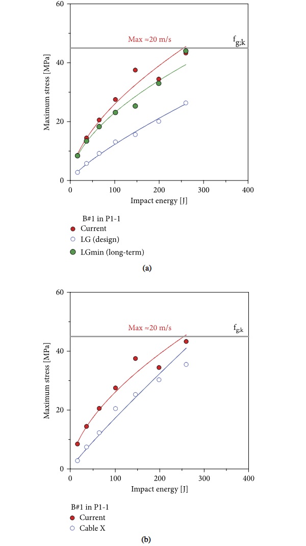
As far as the efficiency of the cable retrofitting system is explored under various impact conditions, Figure 21 shows the effect of cables under P1-1 target and variable speed/energy, under both types of possible retrofit intervention. It can be noted that the bracing cables can offer a relatively high mitigation capacity for the glass panels under various impact energy amplitudes, and thus act as efficient passive mitigation solution able to protect the facade from accidental fracture risk. The “LG (design)” option would be more efficient, but still sensitive to bonding efficiency of interlayers (“LG (long-term)”) and highly invasive on historic facade components.
7. Conclusions
In this paper, the bird-strike performance of glass facades was investigated with the support of refined Finite Element (FE) numerical models based on Coupled Eulerian Lagrangian (CEL) modelling technique.
Bird-strike analysis and damage prediction, as known, is of particular relevance for aircraft engineering application, where major wing components of fuselage components may suffer for possible collision from birds during flying stage and result in serious structural damage for aircraft components.
In the construction and building sector, where glass is largely used for load-bearing components and even for secondary or nonstructural members, special attention should be paid for this type of accidental action. This is especially the case of historic/existing glass facades, which were not specifically designed to provide a minimum of resistance capacity against ordinary or accidental design actions.
For the purpose of present study, the attention was focused on a large size, circle-based shape glass-steel system which was built in 60 s in a museum and is actually affected by accidental strike of birds. The parametric numerical analysis showed that even soft-body impactors with rather limited mass and medium speed can involve high stress peaks in glass components, and thus represent a possible critical condition to mitigate.
Besides, the optimal design of retrofit interventions can efficiently minimize the maximum dynamic effects on glass components and reduce the potential risk for people.
Data Availability
The data supporting the research study will be shared upon request.
Conflicts of Interest
The authors declare that there are no conflicts of interest.
Acknowledgments
The Municipality of Torviscosa (Italy), Arch. Michele Lazzara, is acknowledged for facilitating the experimental analysis.