Authors: Michaela Zdražilová, Zdeněk Sokol and Martina Eliášová
Source: International Journal of Structural Glass and Advanced Materials Research, Volume 6 No. 1, 2022 DOI: https://doi.org/10.3844/sgamrsp.2022.8.14
Abstract
Embedded laminated point connections represent a progressive way of glass structures connecting. However, detail information about their performance is not available yet and the design procedure is mostly based on experimental work and previous experience of designers. Within an ongoing research at the Faculty of Civil Engineering of the Czech Technical University in Prague, a set of real-scale insulating glass panels with embedded laminated point connections was tested. The goal of the experiment was to determine the load bearing capacity and characteristics of this type of glass panel under short-term and long-term loads.
There were three different types of panels used for the experiment. The specimens consisted of different combinations of glass plies (ESG, TVG) and plies of different thicknesses. However, all the specimens were identically sized and there was one embedded steel countersunk bolt liners in each panel’s corner. The laminated glass plies were bonded by two layers of an EVA foil in all cases. During the experiment, all the samples were placed horizontally using the embedded point connections. The applied load was gradually increasing until the collapse. Vertical deflections in specific points of the samples were measured. The temperature and the humidity were monitored as well.
Introduction
The trends in modern architecture are heading towards a maximum transparency of structures, which requires minimizing the surface of the glass structures connections and led to a development of point connections. However, the connections are the most problematic part of a structural glass design and detail information about their performance is not available yet.
Embedded laminated point connections represent a progressive way of glass structures connecting. It is a combination of mechanical bolted and adhesive point fixing systems. It consists of a steel element (bolt) with suitable plastic pads, preventing a direct contact between the glass and the steel, embedded between two (or more) glass plies. The embedded steel element and a glass ply are bonded together with another glass ply by an adhesive represented by a thin foil. The interlayer foils are typically made of Ethylene Vinyl Acetate (EVA), Poly Vinyl Butaryl (PVB) or transparent ionomers (SentryGlas) (Bedon and Santarsiero, 2018).
The advantage of this connection is that due to identical manufacturing process as for the laminated glass, the panels are immediately ready for the application on site.
The design procedure of this type of connection is mostly based on experimental work and previous experience of designers (Carvalho et al, 2010; Cruz et al., 2014). Therefore, there are several ongoing researches dealing with this topic.
An ongoing research at the Faculty of Civil Engineering of the Czech Technical University in Prague is focused on this type of connection. Several experiments were performed using small scale specimens in order to reveal the characteristics of the embedded laminated connection under different types of loads (Zdražilová et al., 2020). The small scale tests were followed by experiments performed on real scale glass panels suitable for façade, roof or banister applications.
This study is dealing with an application of the embedded laminated connection on different types of insulating glass panels. The goal of the experiments was to verify the knowledge about the behavior of the connection obtained from the small scale tests and reveal the short and long term load bearing capacity of the real scale insulating glass panels.
Specimens
Insulating glass panels with embedded laminated point connections were used for the experiment. Generally, insulating glass consists of two glass panes separated by a space, which reduces a heat transfer. The distance between the panes is provided by a spacer. The spacer also seals the gas (air, argon, etc.) between the panes. In order to preserve its insulation effect, the panels should be joined to the rest of the structure without breaching its uniform surface. Therefore, common point mechanical connections based on the classic or countersunk-head stainless steel bolts are problematic to use due to a necessary drilling process and sealing of the interspace. Undercut anchors (Tibolt and Odenbreit, 2014) can be used. In this system, a cylindrical hole and a subsequent undercut is made in the glass ply. The hole is not drilled through the whole glass ply. This type of connection suffers from stress peaks and a may lack of a post-fracture safety.
On the other hand, the embedded laminated point connection represents a possible way. The advantage of using this type of connecting system for insulating panels lies in the fact that the steel element does not pass the whole glass layer and only one glass ply may be drilled. The outer laminated ply remains seamless, as well as the whole outer layer. The panel stays sealed and fulfils aesthetical standards of modern architecture at the same time.
Description of the Specimens
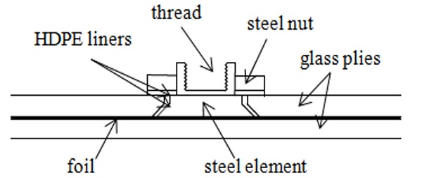
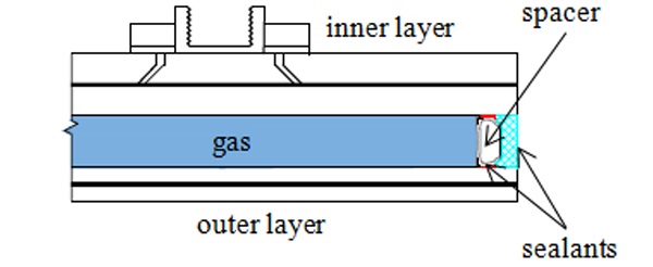
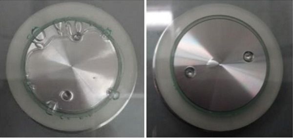
Three sets of equally sized insulating glass panels were provided for the experiment. The length and the width of each specimen were 1500 mm. There was one embedded steel element in each corner of the specimen (four in total). The direct contact between the glass ply and the steel element was prevented by two HDPE (high density polyethylene) liners (Fig. 1). All specimens included two different glass layers. There was a warm edge type plastic spacer (TGI-W 15) placed between the layers; and the whole panel was sealed with polyurethane (Fig. 2).
The TGI-W spacer is made of polypropylene coated by a thin layer of stainless steel. This combination of materials allows bending in the corners of the panels (Izoltechnik, 2011 -2021).
Each set of specimens consisted of insulating panels differing in the thickness or type of glass plies.
Set I
The first set consisted of two layers of laminated glass. The outer layer included two float glass plies with the thickness of 4 mm each, bonded with two layers of an EVA foil with a total thickness of 0.76 mm. The inner layer consisted of one float glass ply and one thermally toughened (ESG) glass ply. The ESG ply included drilled holes for placing the steel bolts. The thickness of each ply was 8 mm. The plies were also bonded with two layers of an EVA foil with a total thickness of 0.76 mm.
Set II
The second set consisted of two layers of laminated glass as well. The outer layer was identical as for the set I specimens. The inner layer also included two 8 mm glass plies bonded with two layers of an EVA foil. However, the ply with drilled holes was made of heat strengthened (TVG) glass.
Set III
The outer layer of the third set specimens was represented by a simple ESG glass ply with the thickness of 8 mm. The inner layer was made of two ESG glass plies with the thickness of 8 mm bonded with two layers of an EVA foil.
Manufacturing Defects
Before the experiment, all the specimens were checked in order to reveal manufacturing defects. Majority of specimens included bubbles (Fig. 3) in the area of connections. The bubbles should not affect the performance of the connection, although they are unacceptable for the aesthetical reasons.
Experimental Work
The experiment was divided into two parts. In the first part of the experiment, all types of glass panels were subjected to a short-term load. The second part was dealing with a long-term load applied on one type of the insulating panel. The tests should reveal the characteristics of these types of panels under different types of loads, load–bearing capacity and confirm the expected collapse mode.
Short-Term Tests
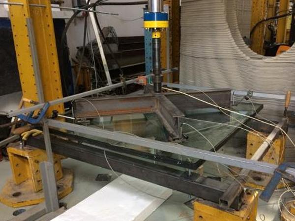
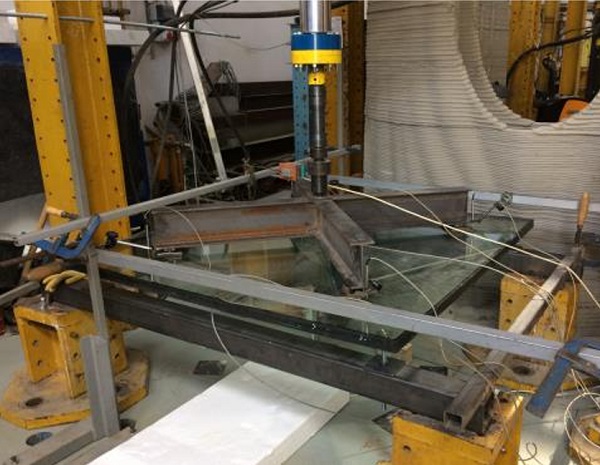
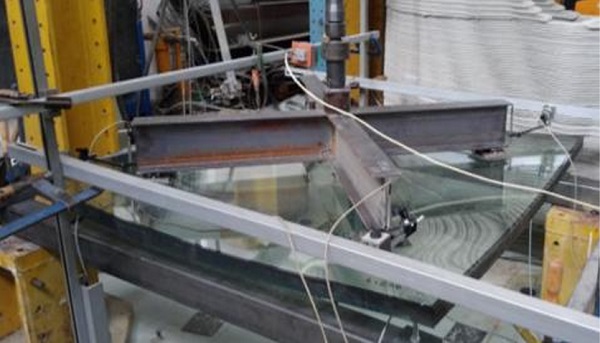
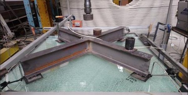
Each set (I, II, III) used for the short-term tests included two specimens. During the experiment, the specimens were placed horizontally and were supported by threatened bars. The load was applied by a single hydraulic jack and it was distributed using a steel X-shaped grid (Fig. 4). The load was applied on the layer without the embedded connections (outer layer). In a real application, that would be the layer facing the wind or a random impact.
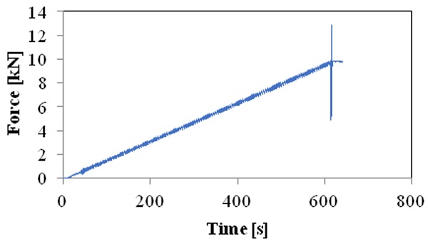
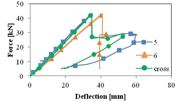
The load was applied at a constant speed of 1 kN/min. The load was constantly increasing until the fracture of any part of the glass panel. A shown graph (Fig. 5) represents a loading cycle of one of the specimens.
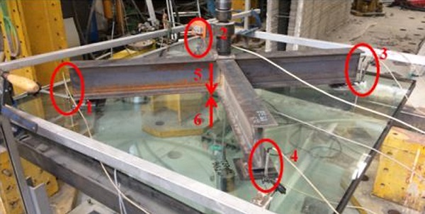
Vertical displacement of the steel grid was monitored during the experiment. Moreover, vertical deflections at four points close to the edge of the steel grid and vertical deflections in the middle of the outer and inner layers were measured. The measured points were situated according to a scheme in the Fig. 6. Stresses in 1-4 points were measured as well. The experiments were performed at a temperature of 25°C.
Results of the Short-Term Tests
The experiment proved a brittle failure of all test specimens. However, there were some differences in the failure among the sets of specimens.
Set I
Both specimens in the set I were loaded until the first fracture of any part of the specimen. Typically, both glass plies of the outer layer fractured nearly at the same time due to reaching the tensile strength limit. The spider-shaped fractures concentrated in the area of the steel grid (Fig. 7 and 8). The inner layer of laminated glass with the embedded point connections remained undamaged. The specimens were capable to withstand a force of 11.3 kN on average.
Set II
The course of the experiment for the set II specimens was basically identical. Both glass plies of the outer layer fractured almost at the same time and the inner layer remained undamaged. However, the value of load was considerably higher, as the specimens were capable to withstand a force of 14.65 kN on average. A graph in the Fig. 9 represents deflections of one of the specimens. Deflections of points 1,2,3,4 correspond to the displacement of the steel cross. Measured deflections of points 5 and 6, copy the trend of the steel cross until the fracture of the outer layer. The course of the deflections of set I and set II is essentially identical due to the float glass outer layer.
Set III
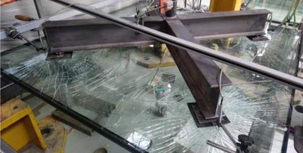
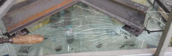
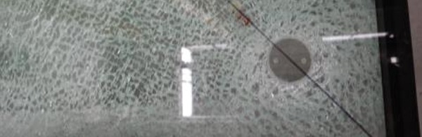
The first set III specimen was tested in the same way as in the previous cases. The specimen was loaded at a constant speed until the fracture of any part of the specimen. In this case, the drilled ESG glass ply fractured in small, relatively harmless dices typical for this type of glass (Fig. 10). The glass fractured due to reaching the tensile strength limit in the mid-span caused by the bending of the panel (Fig. 11). The other ESG ply remained undamaged as well as the outer ESG ply. After the fracture of the drilled ply, it was possible to pull the point connections out of the specimen. The steel elements debonded from the foil. However, the foil remained undamaged (Fig. 12).
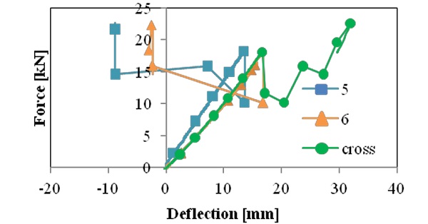
The second specimen was also loaded until the fracture of any part of the specimen. Its behavior was identical as in the previous case. The deflections are shown in the graph in the Fig. 13. Deflection of point 5 copies the trend of the steel cross the whole time.
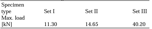
Table 1: Maximum average fracture loads
The deflection of the inner layer (point 6) copies the displacement of the steel cross only until the fracture. After the fracture of the inner layer, the specimen was unloaded and loaded again until the complete collapse. The steel elements debonded from the foil but the foil remained undamaged.
On average, this type of insulating glass panel was capable to withstand a load of 40.2 kN. The fractured panel subsequently collapsed at a load of 35.7 kN.
Comparison
The maximum reached values of forces at the moment of fracture are compared in the Table 1. The results imply that the set III specimens have the potential to bear the highest loads. On the other hand, this type of panel does not seem to provide sufficient post-breakage behavior due to pulling out of the steel connecting elements.
However, obtained results confirmed the small-scale tests findings. Glass panels fracture due to reaching the tensile resistance limit of glass caused by bending. In case of debonding of the embedded steel element from the foil, the foil remains undamaged.
Long-Term Test
The second part of the experiment was dealing with a long-term load bearing capacity of an insulating panel. A set I type of panel was used for the experiment. The insulating panel was placed horizontally using the embedded connections and threaded bars as during the short-term tests.
The Arrangement of the Experiment
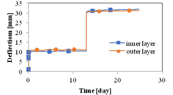
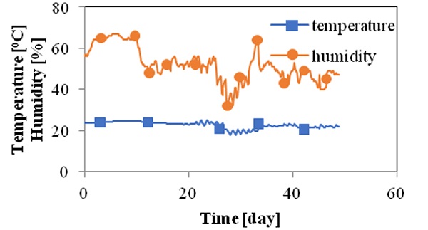
Within the long-term test, the insulating panel was loaded by weight bars and sacks of lead in order to create uniform load. The load was gradually increasing until a complete collapse of the panel. Deflections in the middle of the inner and outer layers were measured. The temperature and humidity were monitored the whole time.
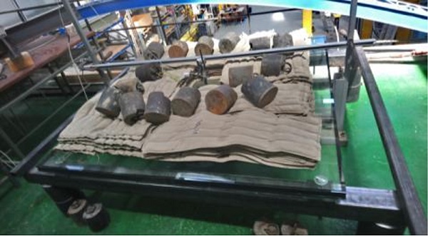
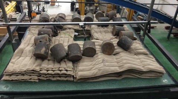
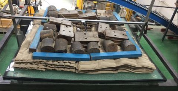
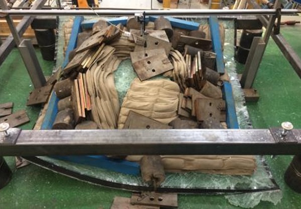
The Course of the Experiment
As a first step, the panel was loaded with the weight of 524 kg and left for 12 days (Fig. 14). After 12 days, the inner layer was found fractured (Fig. 15). The load was increased to 832 kg (Fig. 16) and kept until the complete collapse of the insulating panel. The panel was found collapsed (Fig. 17) The experiment took 43 days after another 21 days in total .

Results of the LongTerm Test
After the collapse, the glass panel was pulled out of the steel connecting elements. The steel elements along with the threaded bars stayed on its places (Fig. 18). The foil was not damaged.
A graph in the Fig. 19 represents the loading scheme of the speci men. The panel was capable to bear the load of 524 kg (3.5 kN/m²) for 12 days. The fractured panel showed a promising postto bear the load of 832 kg (5.5 kN/m breakage capacity as it was able 2 ) for 21 days. Bending of the laminated glass layers represents the graph in the Fig. 20. Measured temperature and humidity are shown in the graph in the Fig. 21.
Conclusion
Three different sets of insulating glass panels with four embedded laminated connections were tested in order to reveal the failure mode and a lo ad bearing capacity. The experiment was divided into two parts.
The shortterm and longterm loads were applied to the surface of the insulating panels. Obtained results imply a potential of this type of panel to bear higher loads than are expected in the real applications.
Moreover, the experiment proved the assumptions obtained from previously performed small-scale tests – the panels with embedded laminated connections collapse due to reaching the tensile resistance limit of glass due to a bending moment. The panels do not collapse because of stresses arising around the connections. After the collapse of the connection, the steel element debonds from the foil without damaging the foil itself.
Nevertheless, more tests should be performed to determine the exact collapse load and a mode of failure. Further research consisting of more full scale tests for applications and numerical modeling is in progress.
Acknowledgement
This study was prepared with a support of grants Hidden Connection of Laminated Glass Panes No. TH 03010175 of the Technology Agency of the Czech Republic (TAČR) and SGS of the Czech Technical University SGS19/150/OHK1/3T/11. The authors would like to thank OGB s.r.o for the cooperation and providing of the samples.
Author’s Contributions
Michaela Zdražilová: Interpretation of data, writing the manuscript. Zdeněk Sokol and Martina Eliášová: Conception and design of study, design of a research plan and supervision.
Ethics
The content of this study will be a part of the doctoral dissertation at The Czech Technical University in Prague (CTU), where further information will be given. The authors confirm there is no conflict of interests and the funding sources had no involvement in a form and content of the research.
References
Bedon, C., & Santarsiero, M. (2018). Transparency in Structural Glass Systems Via Mechanical, Adhesive and Laminated Connections‐Existing Research and Developments. Advanced Engineering Materials, 20(5), 1700815. doi.org/10.1002/adem.201700815
Carvalho, P. L. L., Cruz, P. J. S., Silva, E., & Casal, C. (2010, September). Embedded glass fixing system. In Engineered Transparency; Proc. intern. symp, Düsseldorf, Germany (pp. 29-30). https://www.researchgate.net/publication/272745953 _Embedded_Glass_Fixing_System__Characterization_and_Conceptual_Validation
Cruz, P. J. S., Carvalho, P. L., Silva, E., & Rocha, P. (2014). Embedded point fittings in laminated and double insulating units. Challenging Glass, 4, 331338. doi.org/10.1201/b16499-49
Izoltechnik czech s.r.o., 2011-2021. https://www.izoltechnik.cz/produktyizoltechnik/vchodove-dvere/zaskleni/distancniramecek
Tibolt, M., & Odenbreit, C. (2014). The stress peak at the borehole of point-fitted IGU with undercut anchors. Journal of Facade Design and Engineering, 2(1-2), 3366. doi.org/10.3233/FDE-130011
Zdražilová, M., Sokol, Z., & Eliášová, M. (2020, September). Tests of the embedded laminated glass connection under short-term tensile and eccentric shear loads. In Challenging Glass Conference Proceedings (Vol. 7). doi.org/10.7480/cgc.7.4471