Source: Glass Structures & Engineering
Authors: Philipp Amir Chhadeh, Khodor Sleiman, Henriette Hoffmann, Nicole Funke, Katharina Rettschlag, Peter Jäschke, Mascha Baitinger, Ulrich Knaack, Stefan Kaierle & Matthias Seel
DOI: https://doi.org/10.1007/s40940-024-00290-z
Abstract
Additive manufacturing (AM) has opened new possibilities in many disciplines. Complex geometries can now be created from a variety of materials and material compositions that were previously unimaginable. As a result, there is also the potential for customization and personalization for each user. The present paper and the related research provide insight into the possibilities to further process glass by additive manufacturing methods and thereby exploring the potential for the built environment. This research focuses on developing AM glass components to be used as point fixings for flat glass elements. The innovative laser glass deposition printing process (LGD), developed by Laser Zentrum Hannover e.V., involves locally heating fused silica glass fibres with a CO2-laser, enabling precise deposition of viscose glass on substrates of the same material. In order to implement the LGD process in glass facades an examination of the component is required. This paper introduces a series of mechanical examination techniques, such as indentation and bending tests. The results derived from the testing are the foundation for a parameter study in order to develop a button shaped point fixing for glass facades.
1 Introduction
This research focuses on the examination of additively manufactured glass components for the built environment. The investigated AM process is the Laser glass deposition (LGD) process developed at the Laser Centre Hannover e.V. (Sleiman 2022a).
Inspired by the glassblowing process, first investigations into the thermoforming or fusing of flat glass for architectural application have been done. Belis et al. (2006) presented the first studies on the seamless joining of soda-lime float glass by welding. Since then, further research has been carried out as a precursor to 3D printing of glass. For example, the studies on thermally bonded glass by Rammig (2012) and Eskes et al. (2020). The mechanical properties of AM glass investigated in this paper continue the work of Seel et al. (2018). Initial results of the investigation of AM glass components produced using the LGD process have already been published as part of the proceedings of the Glass performance days 2023 (Chhadeh et al. 2023).
In the section State of the art a brief overview of current AM glass technologies is given. In the following section the motivation for realising AM glass structures in the built environment is discussed by evaluating first applications in consideration of the feasibility.
The subsequent sections present the technology used here to manufacture the first complex AM glass components from fused silica for load bearing tests with LGD process. The mechanical tests are carried out in order to examine the AM glass specimen and have a base knowledge on how to implement these in the built environment. After the study of the behaviour of AM glass specimen the results are used to design a point fixing by utilising AM glass. For this an iterative design process is presented in Sect. 4 to find an optimal point fixing geometry, taking into account process parameters of the AM glass process, installation restrictions and loads acting on the component.
1.1 State of the art
Several approaches for the additive manufacturing of glass materials can be found in the literature. These can be broadly categorized into powder-based processes, processes using resin composites, extrusion processes, and welding processes. For glass materials other than fused silica, extrusion-based processes were developed and are commercially available, where molten glass is deposited through a crucible (Klein et al. 2015). Maple Glass Printing Ltd., an Australian Company and Evenline Ltd., a company based in the United States of America, are currently two prominent companies capable of manufacturing and distributing additively manufactured glass.
Sintering processes of fused silica glass powder materials were developed using an infrared laser and a scanning system. The sinter process enables a high level of complexity, while the transparency and the surface roughness pose challenges (Fateri et al. 2014). In addition, stereolithography-based processes have been developed in which the glass particles are mixed in polymer binders, creating a resin, in order to avoid the high processing temperatures of the glass materials. The created brown bodies are subsequently annealed in a furnace process to release the polymer binders and then sintered to form dense glass bodies. The sintering, however, results in a shrinkage of the glass structure (Kotz et al. 2017).
The majority of experience with glass facades is derived from the utilization of flat glass sheets. Consequently, the initial applications of AM glass are naturally expected to be in this area. It is therefore advantageous to investigate an AM process that applies or fuses glass to flat glass sheet. This requirement is met by the deposition welding processes. Here, either fiber/rod-shaped (Luo et al. 2017; Von Witzendorff et al. 2018) or powdered filler (Maniewski 2022) materials are melted using an external heat source, such as a CO2 laser (Sleiman 2022a). The Laser Glass Deposition (LGD) process used in this research is a fused silica glass fiber-based deposition welding process with a CO2 laser as the heat source. In this process the fused silica glass fiber is fused to a quartz glass plate, creating a homogenous bond between filament and glass plate.
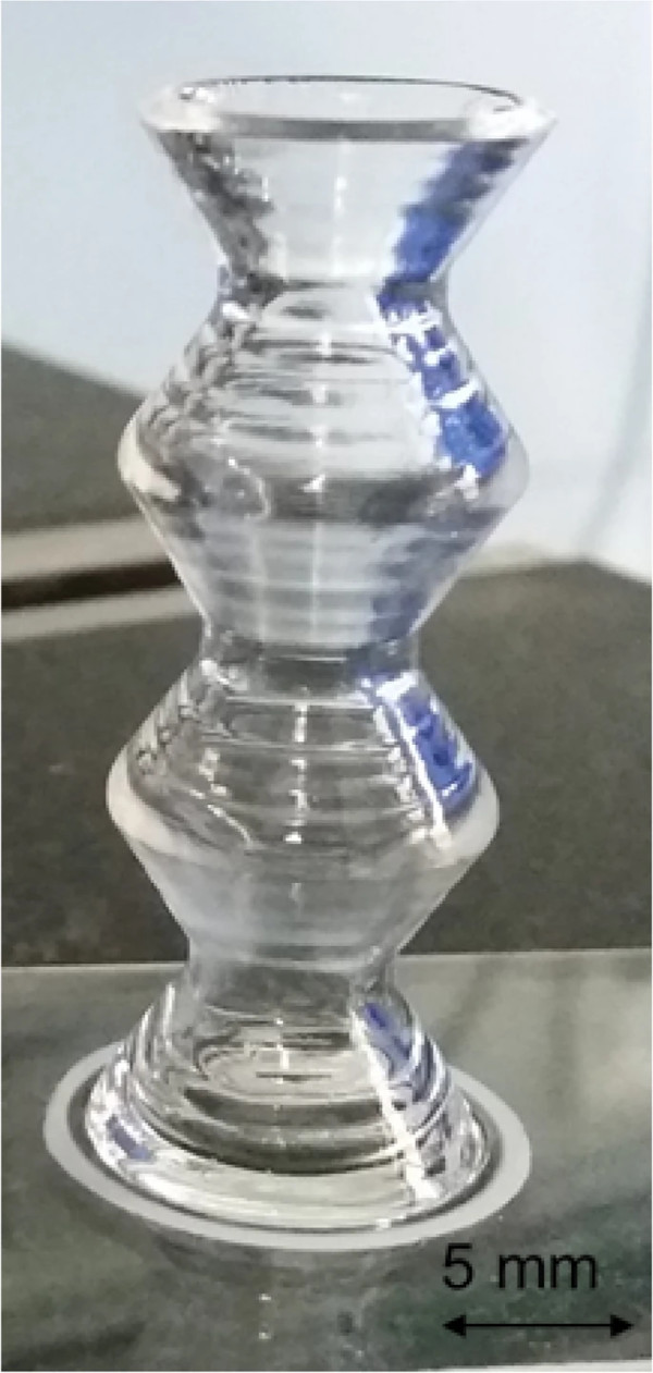
The possible size of AM glass components with the LGD process (of fused silica) is generally limited to the size of the kinematic system. For small structural sizes below 100 × 100 mm, complex structures have already been shown. For example, Fig. 1 showcasing the capability of 3D printing overhang structures by the LGD process. Fused silica glass does not require a heated chamber due to its very low coefficient of thermal expansion (Scholze 2012). The disadvantage of processing fused silica glass are the expensive material costs and higher energy demand due to the higher melting temperatures in comparison to soda-lime silicate glass.
Since soda-lime silicate glass is used in facades, it is necessary to investigate this material. The basic feasibility of additive manufacturing of soda-lime silicate glass to a float glass plate has already been demonstrated by Fröhlich et al. (2021). Nonetheless the processes using soda-lime silicate glass require a heated printing chamber, which currently limits the maximum size of AM glass components made by soda-lime silicate glass. In its early stages, the complexity of the AM glass specimen made with soda-lime silicate glass is limited.
As the process with fused silica is already more advanced and is capable of reliably producing complex 3D geometries, the LGD process with fused silica glass fibers was chosen for this research project.
The investigation methods presented in this paper can also be applied to other AM methods and glass types. In the meantime, first proof of concepts for designing with AM glass will be investigated by using fused silica glass.
1.2 Motivation
The motivation for utilising AM Glass in the built environment is to improve the performance of glass.
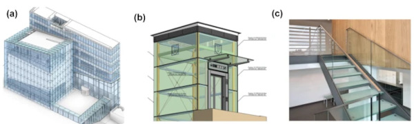
AM Glass can be employed to reinforce large glass panes in order to reduce deflection, mount flat glass panes to a substructure, or to modify the building physics properties of glass, for instance by reflecting light. The limiting factor in AM Glass applications is currently the restriction in the size of the printing area. The technologies have not yet reached the stage where large stiffeners can be applied to reinforce large-format glass panes. Due to these limitations, the focus of this paper is to investigate the feasibility of a design of a point fixing made with the LGD process from fused silica. Three conventional principal types of construction are shown in Fig. 2.
Fasteners for fixing glass components (e.g. made of metal) often detract from the aesthetics. In addition, such connecting elements—as well as adhesives—can impair the durability and weather resistance of glass elements. Large temperature fluctuations can, for example, lead to the decomposition of an adhesive or result in cracks in the uniform connecting elements due to the different thermal expansion coefficients of glass and metal.
The problems relating to the aesthetics and stability of the fixings can be solved by using AM glass.
The problems relating to the aesthetics and stability of the fixings can be solved by using AM glass point fixings made of the same glass material as the actual glass plate. With additive manufacturing of glass a comparatively high degree of shape variability of such components can be achieved. The possible applications of glass constructions with point fixings realized by AM glass can vary widely.
This paper concentrates on cold façade applications, where the outer shell is often realized in glass and serves as weather protection and architectural design. The layer of air between the two shells is used for ventilation and thus for the removal of moisture. The elements can therefore easily be hooked into profiles in the same way as classic sheet metal façade systems.
2 Additive manufacturing of glass components using the laser glass deposition process
As stated before, in this research the LGD process was employed. The LGD (Von Witzendorff et al. 2018; Sleiman 2022b) process is an AM process based on glass filaments, such as fibers or rods, to form three-dimensional glass structures through a welding process.
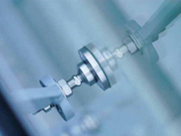
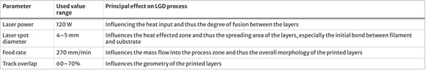
The experimental setup is shown in Fig. 3. A CO2 laser with a wavelength of 10.6 µm (Diamond J3-Coherent) is used as the heat source for melting the fused silica glass filaments (0.4 mm diameter—Weinert Optics GmbH). The laser radiation is directed vertically onto the surface of a quartz glass substrate, which serves as a printing bed. The absorption of the laser radiation generates temperatures of over 2200 °C in the process area; the exact heat gradient can be set via the laser power and axis speed. In this process area, the fused silica glass filament is introduced laterally at a specific feed rate under an angle of 55°. To deposit the fused silica glass filament, the structure is integrated into a 4-axis system consisting of three linear and one rotating axis. The optics holder and the fiber conveyor are attached to the z-axis that can be moved in height. The maximal movement range of the axis system is (1 × 1 × 0.5 m). For the printing of a new layer, the z-axis is moved vertically by an increment based on the previous layer height. A camera (IDS Imaging U3-3880SE-EdmundOprics Ltd) is mounted on the same axis to monitor the deposition process and the layer height. The most relevant parameters that influence the deposition morphology of the final components are listed in Table 1 with their respective effects on the LGD process.
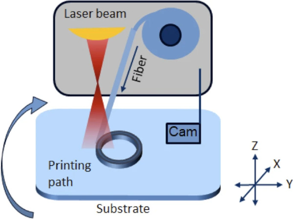
Table 1 Most relevant process parameters and their influence on the process - Full size table
The key requirement for printed test specimens is a smooth and homogeneous layer quality. To achieve this, the layers must be completely fused together so that no wave-like surface contour is created. This requires working at a slow feed rate to ensure sufficient time for the layers to fuse properly. However, this leads to long process times. For example the specimen in Fig. 4 is 1–2 h. Optimizing the component geometry is therefore a key aspect of process planning in order to keep printing times as short as possible.
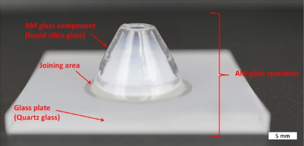
In the paper, the following terminologies are used in relation to AM glass, which are also depicted in the accompanying Fig. 4:
- Glass plate: It is fabricated from quartz glass and serves as the substrate base for the additive manufacturing process.
- AM glass component: This refers to the component that is printed onto the glass plate, utilizing fused silica fibres.
- Joining area: This describes the location of the substance-to-substance between the AM glass component and the glass plate.
- AM glass specimen: This term describes the whole object composed of the AM component and the glass plate.
3 Mechanical investigation of AM glass components produced using the LGD process
The primary objective of the mechanical investigations is to determine whether load can be transferred from the AM glass component to the glass plate. A homogeneous substance-to-substance bond is crucial for achieving this goal. In previous studies, presented in Glass Performance Days 2023 (Chhadeh et al. 2023), the shear loading of AM glass components were investigated. It was observed that a load of 1884 N could be transferred over a joining area of 139 mm2, resulting in an average shear stress of 13.5 MPa and an average bending stress of 34.5 MPa in the joining area. Notably, the fracture behaviour was of interest. The resulting crack propagated through the AM glass specimen. This suggests complete fusion between the AM glass component and the glass plate.
In this section different examination methods are introduced to further characterize AM glass specimen.
- Vickers indentation test: The cut and polished cross section of an AM glass specimen is investigated by conducting an indentation mapping. The objective of this test is to evaluate the difference hardness response of the AM glass component, joining area and glass plate. Based on these examinations, it can be determined whether it is a homogeneous object or whether distinctions must be made for the different areas of the AM glass specimen.
- Bending tests: Three point and coaxial double ring bending tests are conducted to analyse the load bearing of AM glass specimen. For on the stiffening effect through adding material is investigated. Through measurement of the deformation and tracking the load, the mechanical material properties such as the young’s modulus can be calculated. Additionally, the failure behaviour of AM glass specimens can be further investigated in order to answer the following questions: Where is the origin of the crack, how does the crack propagate throughout the specimen? How does the stress state at failure compare to the typical load bearing capacity of glass.
The results of this section will serve in the future to describe the material properties of AM Glass.
3.1 Cross section indentation tests of AM glass specimen produced by LGD process
To confirm the hypothesis of a homogenous bond between AM glass component and glass plate, a Vickers indentation test was conducted according to EN ISO 6507 (2006). The test involves pressing a diamond indenter body, in the shape of a pyramid with a square base and an angle of 136 degrees between opposite faces, into the surface of the material being tested with a specific, controlled force. The specimen used for this is embodied in a resin, after a grind and polishing process, the indentation can be done on the surface, see Fig. 5a. This test determines the Vickers hardness (HV) of a material. Three series of test studies were conducted on a specimen using 4.905 N as the indentation force.
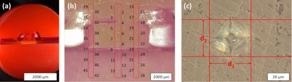
The indentation points are shown in Fig. 5b in three columns, a further enhancement is shown in Fig. 5c. In order to evaluate the Vickers Hardness, the indentation force is divided by the indentation area. The determination of the Vicker hardness (HV05) is calculated by Eq. (1), with F as the indentation force and d1 and d2 as the length of the diagonals, see Fig. 5c:
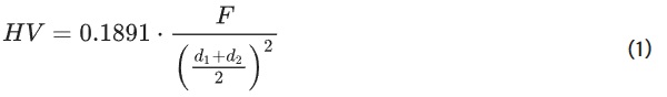
Figure 6 shows the calculated Vickers hardness of the three indentation series, S1 (Indenter Points 1–14), S2 (Indenter Points 15–28) and S3 (Indenter Points 29–42). The vertical distance between the points are 0.6 mm and the horizontal distance between the series are 4 mm.
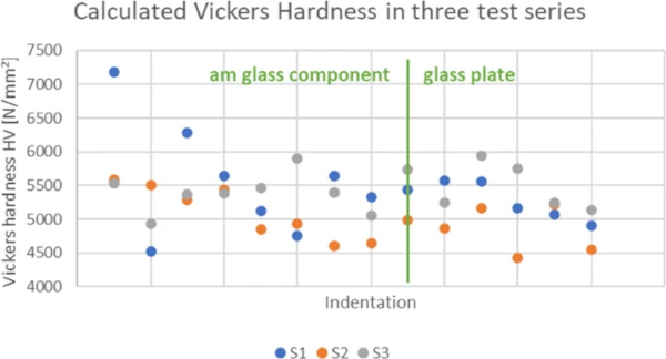
The average calculated Vickers hardness HV05 in the AM glass component is 5346 N/mm2 with a standard deviation of 577 MPa and in the glass plate 5198 N/mm2 with a standard deviation of 401 MPa. The overall average Vickers hardness of the AM glass specimen is 5283 N/mm2 with a standard deviation of 507 MPa. The average values for the Vickers hardness of quartz glass in literature ranges between 6230 N/mm2 (Yamane and Mackenzie 1974) and 6500 N/mm2 (Neely and Mackenzie 1968).
The measured Vickers hardness response is lower than the comparative values found in the literature. Nevertheless, it is evident that the material properties do not differ between the AM glass component and the glass plate allowing for the assumption that the material properties of flat quartz glass also extend to the AM glass component.
The deviation in the measured values may be due to the indentation force. Bruns et al. (2020) investigated the effect of indentation force on material densification and crack behaviour. It is possible that the chosen indentation force of 4.905 N is at a magnitude that results in divergent Vickers hardness measurements at certain points.
3.2 Load bearing tests of AM glass specimen produced by LGD process
Similar to the conducted shear tests, bending tests are used to determine the strength of AM glass components by LGD process. A three-point bending test and a coaxial double ring bending test were conducted, under standard climatic conditions using the Zwick Roell Z050. The loads were force-controlled with a stress rate target of 2 MPa/s, as suggested in EN 1288-3 (2000a) and EN 1288-5 (2000b). The dimensions of the test setups are determined by the size of the AM glass specimen, currently a quartz glass plate of 100 × 50 mm and 100 × 100 mm is a feasible size for the LGD process to use as a print bed. The two investigated designs for the specimens are shown in Fig. 7 one the left for the three-point bending test and on the right for the coaxial double ring bending test.

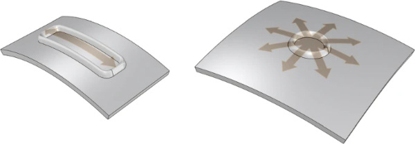
The objective of the three-point bending test is to analyse the stress state alongside the AM glass component. The coaxial double ring bending test is implemented to analyse tensile stress perpendicular to the AM glass component. Figure 8 shows a schematic sketch of the bending direction with the orange arrows indicating the direction of the maximal principal stress in the AM Glass specimens.
3.2.1 Three-point bending test
The three-point bending test was selected for its ability to create a simple and comprehensible stress state in the additively manufactured (AM) glass specimen. This test generates tensile stress on the underside of the specimen, with the maximum stress occurring directly beneath the load roller, where the fracture is expected to initiate.
The primary objectives of this test are to determine the bending strength of the AM glass specimen and to investigate its stiffness response, particularly in comparison to a conventional quartz glass plate without an AM glass component. Additionally, the test aims to evaluate the mechanical material properties to gather essential data for designing with AM glass.
A strain gauge strip (Tokyo Sokki Strain Gauges FLA-2-8) is applied to the center of the underside of the AM glass specimen. The strain measurements obtained can be reproduced using finite element (FE) modelling on a photogrammetrically created digital twin.
3.2.1.1 Specimen production and test set up of three point bending test
A specimen produced for the three-point bending test are shown in Fig. 9. The rectangular, elliptic shape of the AM glass component is a result of the process parameters, as a higher quality AM glass component is produced when the fibre is laid down continuously. The rounded connection between the substrate and the initial layer is achieved by the disproportionately large laser spot diameter compared to the filament diameter. The large heat-affected zone provides the low-viscosity glass with the largest possible propagation area. To achieve smooth surfaces, the layers must be completely fused together. For this purpose, the laser spot diameter, i.e. the heat-affected zone, must be larger than the width of a deposited filament. However, the complete fusion of the layers results in a changing wall thickness, which must be incorporated into the printing process. The changing wall width manifests itself in a flank angle of the printed structure.

To print the specified contour and wall thickness, two lines had to be printed next to each other with an overlap of 60%. The resulting width in the first layers is approx. 4.5 mm and at a print height of 4 mm the wall width is approx. 2.5 mm.
As the local heat input from the laser radiation on the glass plate leads to thermal stresses, all samples were subsequently annealed in an oven. For this purpose, the samples are heated up to 1300 °C and cooled down to room temperature over a period of 5 h. The post-treated samples are then examined for thermal stresses using polarized light.
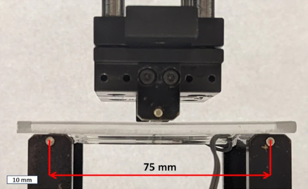
The AM glass component is only located in the area between the supports as the test setup requires a flat surface in the area of the supports. The support rollers are 75 mm apart from each other. The test set up is based on the principles of EN 2000a, the scale of the test set up is adapted to the limited size of the AM glass specimen. Figure 10 shows the testing set up for the three-point bending test. A four-point bending test was not utilized in this case, as the objective was to achieve the lowest possible stress state at the start and end points of the AM glass component. The rectangular shape of the AM glass component creates tensile stress on the short side during the bending test. The goal was to minimize this stress to prevent high tensile forces from occurring transverse to the AM glass component. This bending test’s objective is to examine the tensile strength along the AM glass component. To achieve this, only a central load was applied, minimizing the stresses in the short sides of the AM glass component. Although using two closely spaced load rollers could have been effective, the existing configurations of the four-point bending test impose a minimum distance between the load rollers. At this distance, the stress level at the start and end of the AM glass component was estimated to be too high to ensure unintentional failure at the short sides of the rectangular shaped AM glass component.
3.2.1.2 Results of the three point bending test
Table 2 displays the test results, showing the measured loads at failure and including the mean value µ and standard deviation. The results of the maximum load before failure are showing a high standard deviation. The possible causes of this are discussed below.
Table 2 Results of the three-point bending test - Full size table
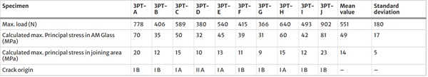
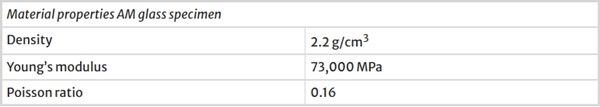
Digital twins are created through systematic positioning of photographs and the use of the software Polycam to create a mesh model. To verify the scan, systematic control measurements are done. In this study, a static structural analysis was conducted using ANSYS Workbench 2023 R1. A body fitted cartesian mesh with an element size of 0.5 mm in each direction was employed, ensuring convergence in the simulation results. The analysis was performed with the large deflections option turned off, meaning that second-order nonlinear effects were not considered in the calculations. This approach allowed for a straightforward evaluation of the structural response under the given loading conditions, focusing on linear elastic behaviour. The photogrammetrically created digital twins of the specimen were subjected to the loads in the FE analysis for evaluation. The maximum principal stresses are shown in two locations directly under the load roller: In the top of the AM glass component and in the notch between the AM glass component and the glass plate. For the comparative FE analysis, the AM glass component was assigned the same material properties as the quartz glass plate, see Table 3 (Quarzglas 2024). The specimen was modelled as a homogeneous body. These calculated max principal stresses are shown in Fig. 11 and listed for each Specimen in Table 2.
Table 3 Material properties for modelling AM glass specimen, based on quartz glass properties - Full size table
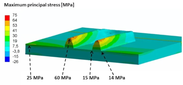
As expected, the highest maximum principal stresses occur at the peak of the AM glass component. The stress decreases in the direction of the glass plate. Only in the notch of the joining area does the change in geometry result in a locally higher stress level compared to the adjacent glass plate. The maximum principal stress increases toward the edge of the glass. The following fracture analysis shows that fractures often originate at the glass edge.
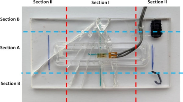
Figure 12 displays the division of the AM glass specimen in multiple sections. The origins of the cracks are listed in Table 2. For example, the crack in Specimen 3PT-J initiated in Section IB, at the edge in the central area of the specimen. In fact, five out of the ten specimens crack origins are in Section IB and one of the specimens failed at the starting point of the AM glass component in section IIA. The other three crack origins are suspected to be within Section IA. The crack origin occurred here around the AM glass component. This phenomenon of different failure locations is likely to be the main reason for the large variation in the test results. Due to the inferior edge quality of the glass plates, failure loads originating at the glass edge also scatter significantly. The glass edges were cut using a laser process, but due to an error in temperature management larger defects occurred along the glass edge. These defects notably influenced the results of the experimental data.
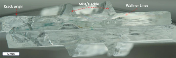
The homogeneous bond is evident in the crack propagation behaviour observed in the AM glass specimen. The crack, initiated at the edge of the glass, propagates through both the glass plate and the AM component without any deviation. In specimen 3PT-J, the crack initiates from the glass edge in section IB, as depicted in Fig. 12. Pinpointing the precise location of the fracture mirror in Fig. 13 presents challenges; however, it is apparent that the Mist and Hackle extend towards the AM glass component, aligning with the direction of the Wallner Lines observed in the glass plate. This behaviour reinforces the assumption that the LGD process creates a homogeneous bond between the quartz glass plate and the fused silica fibre.
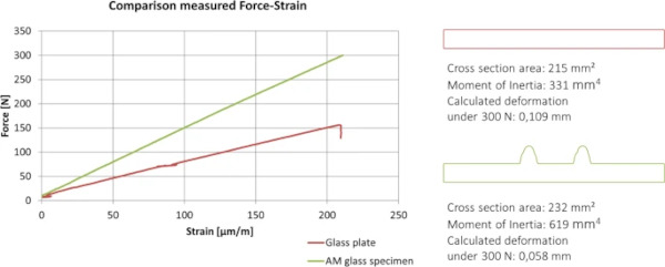
The three-point bending test serves to demonstrate the increase in stiffness by increasing the specimen's moment of inertia. With the digital twin the measured strains at the location of the strain gauge can be reproduced in a FE model under the same load with a deviation of 5–10%. This deviation is within the tolerance range of the strain gauge and the photogrammetric scan.
Figure 14 shows the comparison of the stiffness between a glass plate with and without an AM glass component in a Force-Strain diagram, recorded by the testing machine and the Strain gauges. It is shown that as expected the response of the AM glass specimen is significantly stiffer due to the increase of the moment of inertia. By only increasing the cross-section area about 8% the moment of inertia increases 87%. This also leads to less deformation under the same load.
3.2.2 Coaxial double ring bending test
Additionally to the three-point bending test a coaxial double ring bending test based on EN 2000b with a different set of specimens was conducted.
3.2.2.1 Specimen production and test set up of coaxial double ring bending test
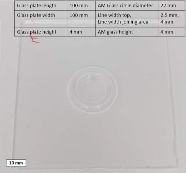
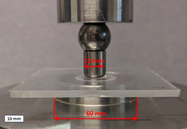
For this test set up a cylindric shaped AM glass component with a diameter of 22 mm, a height of 4 mm and a width of 4 mm in the joining area is fused on a 100 × 100 mm2 square glass plate (thickness 4 mm). The same AM methodology for the set of specimens mentioned above was applied here. For the standardized coaxial double ring bending test a R30 mm diameter support ring and a R6 mm load ring was used, according to EN 2000b. With regard to the design using the R45 support ring proposed in the standard, it had to be determined that this could not be used due to the inferior edge quality of the specimen. The risk of premature failure due to the existing low stresses on the edge was too great to use the R45 support ring.
The test set up and the specimen with measurements are shown in Figs. 15 and 16.
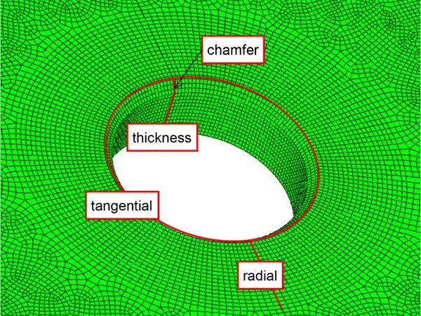
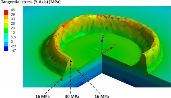
In the standard coaxial double ring bending test the load is applied evenly through both a load and a support ring, achieving a homogeneous stress distribution in the central area of the specimen. This reduces the risk of stress concentrations and allows for a more accurate determination of the material's bending strength. In the evaluation of the test, a distinction between radial and tangential stresses is made.
The application of a glass cylinder to the underside of a flat glass plate leads to non-trivial local stress concentrations during a coaxial double ring bending test. The presence of the cylinder results in a local change in the stiffness of the plate. This change causes stresses to concentrate around the cylinder, especially in the joining area.
Radial stresses run perpendicular to the printed cylinder, resulting in high tensile stress transverse to the notch direction of the joining area. In the cylinder, a tangential tensile stress occurs along the wall of the AM component. The increased stresses around the cylinder elevate the risk of crack formation in the joining area. A detailed assessment requires an in-depth analysis using FE Methods, to understand the stress-states.
3.2.2.2 Results of the coaxial double ring bending test
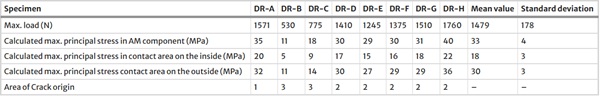
Table 4 presents the results of the eight conducted double ring bending tests, showcasing the maximum load observed at failure. Specimens DR-B and DR-C are identified as outliers. For these two samples, it is noted that the fracture likely initiated from the edge, rendering them unsuitable for evaluation due to premature failure. The mean and standard deviation, provided on the right, exclude specimens DR-B and DR-C.
Table 4 Results of coaxial double ring bending test - Full size table
Digital twins of the AM specimen were created using a photogrammetric method for the coaxial double ring bending tests. The digital twins were modelled as one object with the material properties of quartz glass, see material properties in Table 3, based on insights from the Vickers test and the three point Bending test. As in the Ansys model for the 3-point bending test, the same settings were used for the analysis.
The models were used to analyse stresses at various locations in different directions. Figure 17 displays the radial stress and Fig. 18 the tangential stresses in the AM glass specimen. Radial and tangential stresses contribute to the formation of the maximum principal stresses shown in Fig. 19. In a homogeneous material under symmetric loading, the principal stresses are directly derived from the radial and tangential stresses. However, in this case of a square plate with an AM glass component, the stress state is complex due to the local change in stiffness. The maximum principal stresses are determined by the combination and interaction of all stresses within the material, including radial and tangential stresses, as well as other stress components induced by the loading situation and geometry. The sample points highlighted in Fig. 19 are listed in Table 4 for all specimens. In previous examinations of AM glass specimens produced by the LGD process (Chhadeh et al. 2023), the average calculated tensile stress in the joining area is 34.5 MPa at failure. Despite showing a high standard deviation, the results are in a comparable range to the results recorded in this coaxial double ring bending examination.
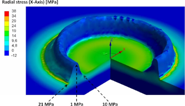
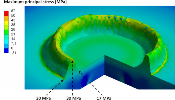
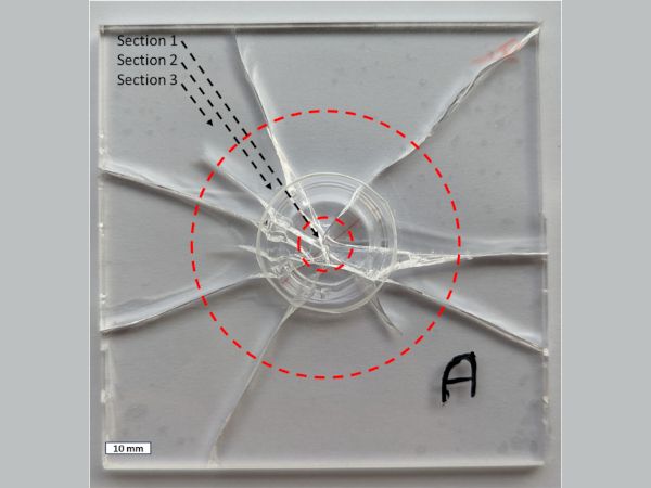
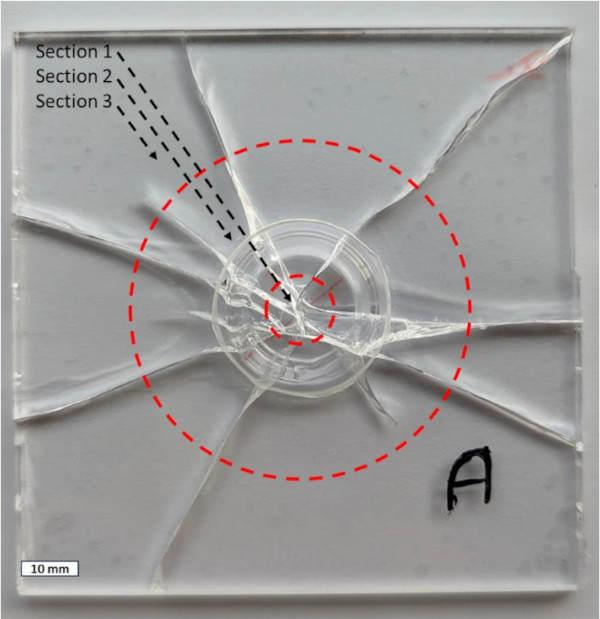
As the maximum principal stress suggests, the origin of fracture can often be traced back to the AM component. In Fig. 20 specimen A after testing is shown. The dotted circles divide the specimen in three sections. Section 1, the area inside the load ring, Sect. 2, the area between load and support ring, and Sect. 3, the area outside of the support ring. The failure origins are listed in Table 4. For example, the failure in the depicted specimen A originates in Sect. 1. For specimens B and C, the crack started in Sect. 3 at the edge of the glass, making the values unusable for evaluation. The failure of the other five specimen occurred around the AM glass component. However, it is challenging to determine whether the fracture initiates from the top of the AM component or from the notch at the joining area between the AM component and the glass plate. Typically, glass fracture occurs at locations where a sufficiently high maximum principal stress intersects with a sufficiently deep surface defect. Due to the elevated stress state around the additive manufactured cylinder, it is possible that a defect on the glass plate surface in this area could lead to glass breakage.
4 Structural design of AM glass point fixings
In Sect. 3, the material resistance aspect of AM glass specimens is examined. In order to conduct a design assessment, Sect. 4 first investigates the impacts on point fixings and subsequently conducts a parameter study to devise an initial design for an AM glass point fixing.
4.1 Structural requirements on AM glass point fixings
The static requirements for the AM glass point fixings are defined by the static loads to be applied on cold façade structures. Loads such as dead load and wind load must be transferred safely by the point fixings into the substructure. The development and optimization of the cross-section shape is therefore based on considering those loads, determined in Fig. 21, in conjunction with Tables 5 and 6.
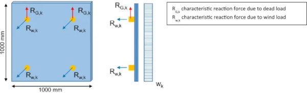
Table 5 Wind loads (Germany) per point fixing (Glass pane 1000 × 1000 [mm]) - Full size table
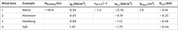
Table 6 Dead weight per point fixing (glass pane 1000 × 1000 [mm]) - Full size table
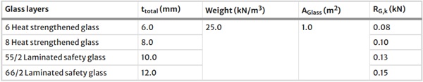
The calculation of the reaction forces is carried out depending on the pane size and the wind load, assuming a statically determined system (transfer of dead weight only via the upper fixings, wind load uniformly across all fixings). Tables 5 and 6 show dead load and wind load for varying glass thicknesses and wind zones based on EN 1991-1-1 (2010a) and EN 1991-1-4 (2010b) and the respective national annex for Germany.
4.2 Comparative FEM analysis
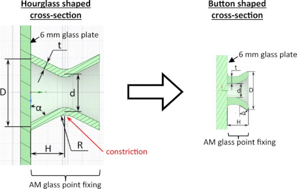
As a first step the cross-section of the point fixing was defined by the shape of an hourglass, inspired by Fig. 1. This geometry was chosen on the basis of metallic point fixings, which are already known from structural glass constructions. Furthermore, the shape depends on the possibilities of the manufacturing process, which was adapted to the required geometries for the construction industry during the project. The hourglass shaped geometry is to be hinged in agraffe profiles, similar to sheet metal facades.
A parameter study was realized on the hourglass shaped cross-section, to identify the parameters, which have a major impact on the load-bearing capacity. The different geometric parameters are varied as follows:
R ...Radius in the middle
D … Diameter at the edge
d … Diameter in the middle
t … Thickness of the structure
α … resulting angle between glass plate and AM-component
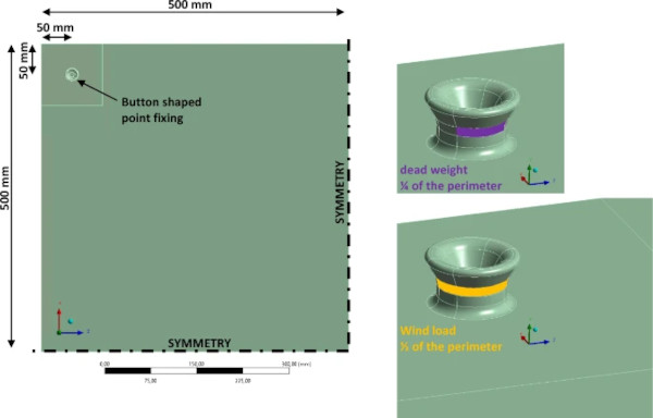
The height H was set to 20 mm and was not varied in the parameter study. This was done to reduce the bending moment in the point fixing by positioning the structure close to the glass pane and thus reducing the height of the cantilever, while also allowing for sufficient space to accommodate construction tolerances in installing the support construction. The distribution of stresses in the AM glass component was evaluated after each parameter variation. In Table 7 the different parameters and their impact on the maximum principal stress in the last two columns are shown. The values for the maximum principal stress are normalized on the basis of the value for position 1, σmax, windload shows the normalized maximum principal stress induced by windload and σmax, deadweight the normalized maximum principal stress induced by deadweight. The evaluated maximum principal stresses show that the cross-section at the constriction of the hourglass shape, where the load is applied, defined by d and t, and the value of the radius R have a major impact on the load-bearing capacity of the hourglass shaped point fixing, whereas the diameter D has a non-significant influence on the results. In addition, it became apparent that the static-constructive requirements had to be harmonized with the manufacturing process and process time. Therefore, the process time could be reduced by reducing the values of D and H without changing r and t. A new optimized geometry was developed, based on manufacturing requirements and the parameter study results. The invented button shaped cross-section could then be optimised using the results of the examined parameters on the hourglass shaped cross-section.
Table 7 Examined and defined parameters for the different geometries - Full size table
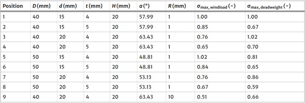
Figure 22 and Table 7 show the parameters of the study of the hourglass shaped geometry and the new, optimized button shaped geometry.
The models for the parameter study each include a glass plate with a fixed support on the lower surface. On the upper surface the point fixing is attached by a bonded contact. Three dimensional elements are used with a linear element order. The finite element size is set to 1 mm in the point fixing and to 6 mm in the glass plate. The number of elements varies with the volume of the hourglass geometry, as the element sizes are fixed. The material is assumed to be linear-elastic. The loads are applied on ¼ of the perimeter at the constriction for the dead weight and on ½ of the perimeter at the constriction for the wind load.
The button shaped fixing is analysed numerically with the maximum loads of dead weight and wind load for wind zone 1 and 6 mm glass (see Tables 5 and 6).
Two load combinations (LC) are considered:
LC1: 1.35 · dead weight + 1.5 · wind suction.
LC2: 1.35 · dead weight.
In comparison to wind suction, the value of wind pressure determined on the basis of EN 2010b is similar or less high. Even though the glass pane with the AM glass component is an asymmetric construction, it is supposed that wind suction is the governing factor. This will be examined in further studies during the project.
Figure 23 shows the model of the glass plate including the AM glass point fixing. The dead weight is applied on a quarter of the perimeter and the wind load on half of the perimeter of the fixing. The results of the maximum principal stress in an area of 100 × 100 (mm) around the point fixing is shown in Fig. 24.
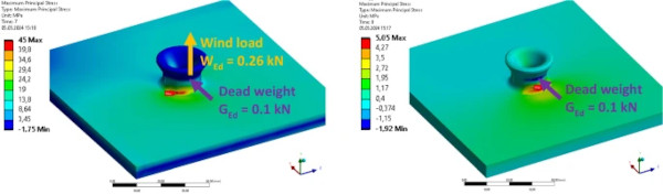
The results of the calculations show that due to dead load (LC2) the maximum stress in the joining area between glass plate and AM glass component is about 5 MPa. The location of the maximum principal stress displays the eccentricity of the geometric centre of the glass pane to the force application area. The maximum flexion occurs in the joining area without offset in x-direction to the load application area.
The results on LC1 show that the additional application of wind load creates a shift of the position of the maximum principal stress to the free edge of the glass pane. The maximum value of 45 MPa for the principal stress combines not only the flexion of the point fixing due to wind and dead load, but also a significant component of the bending of the glass pane.
The so far realised numerical simulations show that the principal stress distribution in the button-shaped point fixing is not only depending on the height of the applied loads, but also on the complex geometry of the fixing itself as well as the glass pane, its rigidity and bending behaviour.
Despite this complex load bearing behaviour of the button shaped point fixing, the stress levels obtained in the numerical simulations are comparable to the stress levels in the already realised experimental investigations (see Sect. 3.2.). The comparison value of the coaxial double ring bending test, for example, which has the maximum principal stress in the joining area, is an average of 30 MPa with a standard deviation of 3 MPa. The dead weight could therefore be supported in this case.
In order to evaluate the stresses of the load case combination with the wind load (LC1), the resulting stresses are compared to an already standardized bolted point fixing (cylindrical hole, plastic washer, metal discs). The boundary conditions of both calculated models are the same. The diameter of the bore hole is 18 mm. The resulting maximum principal stress in the model of the bore hole is 39 MPa, which is in the same range of the maximum principal stress in the model with the AM glass button-shaped point fixing.
To bear the occurring loads, the geometry should be further optimized, or the number of button-shaped point fixings for load transfer must be increased. In order to quantify the influence of each parameter and determine design stresses for the static verification according to the state-of-the-art standards by further numerical studies, the existing model has to be calibrated and confirmed by mechanical tests on the AM glass specimen with button shaped geometry.
As pure quartz glass is not defined as construction product and a very cost intensive material, a process for additively manufactured borosilicate glass or even soda lime silicate-glass will be part of further research in this field.
5 Conclusion
The research presented in this paper focuses on the examination of AM Glass specimen and the resulting opportunities for AM glass point fixings in façades.
Additively manufactured test specimens were produced using the Laser Glass Deposition process. Fused silica fibres with a diameter of 0.4 mm were additively processed using CO2 laser radiation (10.6 µm, 120 W). A suitable choice of track overlap (60–70%) and laser spot diameter (7 mm) made it possible to produce test specimens with a smooth surface, without post processing, suitable for load transfer. The LGD process is continuously developed, and its limits explored to optimize the process. In the future, the transferability of findings from quartz glass to other types of glass (e.g. sodalime silicate glass and borosilicate glass) will be investigated.
The examination of the AM glass specimens has shown several findings. The study observed a homogeneous bond between the glass plate and the AM component. Cracks propagate through both sections in a straight manner. The indentation and bending tests demonstrate that the AM glass specimen can be modelled as one homogeneous body. The study demonstrates that the material properties of quartz glass are transferable to the AM glass specimen, highlighting the effectiveness of the LGD process. The precise LGD process, with its thin filament diameter of 0.4 mm, does not introduce measurable notches into the structure, eliminating the need for an anisotropic model, simplifying its analysis and application. The results showed that the maximum principal stress often occurred near the AM component, increasing the risk of crack formation in this area. Most failure locations were around the AM glass component, likely due to the local change in stiffness caused by the AM component.
6 Outlook
It is important to note that the investigations focused on shallow AM glass components, up to a height of 4 mm, fused to 4 mm glass plates. These mechanical investigations, adapted from EN standards, provide a foundational understanding that can be utilized to compare stress states in designs employing the LGD process. The mechanical investigations demonstrate that a local change in stiffness leads to a higher stress level in the area of the AM glass component. This change in geometry is similar to that of a glass bore hole or glass edge. Structural design of components typically employs reduction factors in these cases. It is envisaged that in the future such a factor will be established for AM glass components. However, this will require more extensive and comprehensive investigations.
In the case of cold façade elements, the examined AM glass components, the point fixings as well as the quartz glass plates, must be able to resist the dead weight of the glass elements and the wind loads on the façade (pressure/suction). In addition, when used in other types of construction, the elements may need to fulfil further requirements depending on the specific construction type, as e.g. fall protection, dynamic impact, or deformation of the substructure.
Moreover, the calculations performed on the finite element model indicate that the maximum principal stresses in an additively manufactured point fixing exhibit a comparable intensity to those observed in a bolted point fixing. The potential for shape optimization through the additive manufacturing process suggests that a greater stress reduction may be achieved by advancing the process parameters of the technology.
At present, AM Glass components are manufactured out of fused silica glass, which is covered neither by a harmonized standard nor the Construction Products Regulation (EU) 305/2011. The material itself as well as the structural design of the point fixings is non-standard and needs to be regulated. The use of the system in the built environment in Germany requires a project related approval (ZiE)/construction technique permit (vBg) or national technical approval (abZ)/general construction technique permit (aBg) issued by the DIBt. Project related ZiE/vBg are issued by the supreme building authorities of the German states. To apply for a ZiE/aBg, information on material behaviour, manufacturing processes, quality controls and consistency of performance as well as admissible stresses and partial safety factors as part of the design concept must be defined, among other things.
The next phase of the research project will cover the questions related to design concept, material resistances and safety factors based on the presented results and mechanical testing of the button shaped AM glass point fixings.
In the future more and more AM glass applications will be investigated. Most prominent for the built environment will be the application of stiffeners on flat glass sheets. This requires the development of larger glass 3D printers that can fuse free-form shapes onto large soda lime silicate float glass sheet (3 × 2 m). Just by adding small amounts of glass, the deflection under load can be significantly reduced. The material savings here harbour great potential for the built environment.