
Authors: Jian Li, Jian Hong, Shiyao Liu, Yuzai Zhou, Guangbo Wang and Chengxiang Xu
Source: E3S Web Conf., 372 (2023) 02014
DOI: https://doi.org/10.1051/e3sconf/202337202014
ABSTRACT: Based on the corridor channel curtain wall reconstruction project at Wuhan Tianhe airport T2- T3 terminal building, the structural system of point supported glass curtain wall with cable structure 18 years ago was analyzed, the technical difficulties of curtain wall glass panel removal and bearing cable removal were studied, and technical measures for the dismantlement and reconstruction of point supported glass curtain wall with cable structure were reasonably proposed. During the construction process of the dismantlement and reconstruction, the curtain wall structure was dynamically monitored, the deformation of the monitoring points were small, and the construction process was in a safe state. Due to the success in the dismantlement and reconstruction control technology of the point supported glass curtain wall with cable structure in this project, it not only ensured the construction safety, but also improved the construction quality, which could provide a reference for other similar projects.
1. INTRODUCTION
With the vigorous implementation of the urban renewal plan, it is necessary to renovate the old buildings. In this process, the airport terminal buildings that did not adapt to the development of modern technology and industry have been overhauled, repaired and transformed. It can effectively increase the passenger capacity of the airport and avoid the high cost of building a new airport. [1] Airport terminals mostly use cable points to support glass curtain walls. This kind of structural system has the advantages of no frame, no support of large scale steel structure, light in weight, and transparent and wide vision. Moreover, it is suitable for carrying large spans and large height external curtain walls. [2,3]
The cable structure point supported glass curtain wall structure is complex, and the construction is difficult. Thus, safe and rapid construction is particularly important. Wang et al. [4]presented the construction technology of the combined point-supporting glass curtain wall with high cable net. It enabled the accurate installation of large cable-point curtain walls in complex structural systems. Yang [5] studied the construction technology of large span arc cable glass curtain wall. This technology ensured the quality of glass curtain wall installation. Duan et al. [6] studied the key construction technology of rhombic-arcpoint-styled glass curtain wall. Zhang et al. [7] proposed cable tension technology to avoid the intersection of prestressed construction and glass installation. Wang et al. [8] studied the technical points of prestressed cable tension of curtain wall based on a specific construction project. In the aspect of curtain wall structure glass dismantlement, scholars have proposed the partial dismantlement method [9,10], and the rapid dismantlement method [11]. These technologies provide great convenience for curtain wall construction.
According to the characteristics of the structural system of the point supported glass curtain wall with cable structure, this paper takes the curtain wall reconstruction project of the Wuhan Tianhe Airport T2-T3 Terminal building as the research object, focussing on the technical difficulties in the removal of the glass panel of the curtain wall and the removal of the load-bearing cable, and puts forward reasonable technical measures for the removal and reconstruction of the point supported glass curtain wall with cable structure. In the process of dismantlement and reconstruction, the dynamic monitoring of the curtain wall structure was carried out to ensure the safety of dismantlement and reconstruction, which could provide a reference for other similar projects.
2. ENGINEERING SITUATION
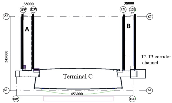
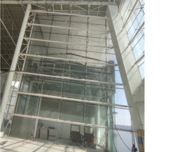
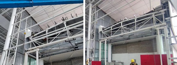
Wuhan Tianhe airport T2 terminal reconstruction project covered a total construction area of 158400 square meters, which is composed of terminal hall, A corridor, B corridor, and connecting corridor. The main building of the terminal is a frame structure. The roof of the hall is a triangular space truss structure. The roof of the corridor is a portal steel frame structure. In addition, the roof of the corridor is a space truss structure. At present, because a new corridor was built in T3 terminal to connect with T2 terminal, it is necessary to transform the curtain wall at T2-T3 corridor to connect T2 and T3 terminal corridors (as shown in Figure 1). The curtain wall is trapezoidal, the bottom length was 19.0 m and the height of the left curtain wall was 22.877 m. The height of the right curtain wall was 22.176 m and the total area of the glass curtain wall was about 375.92 square meters. The curtain wall was divided into upper and lower layers. The second layer elevation of 7.5 m. The glass was 12(low-E)+12A+12 double toughened hollow glass with a dimension of 3000 mm x 2000 mm. The curtain wall scene diagram is shown in Figure 2, and the facade and profile of the curtain wall are shown in Figure 3.
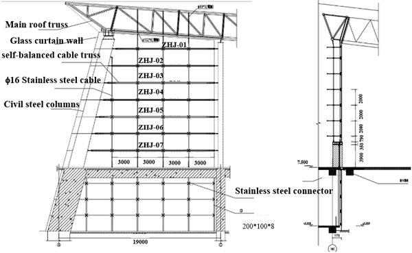
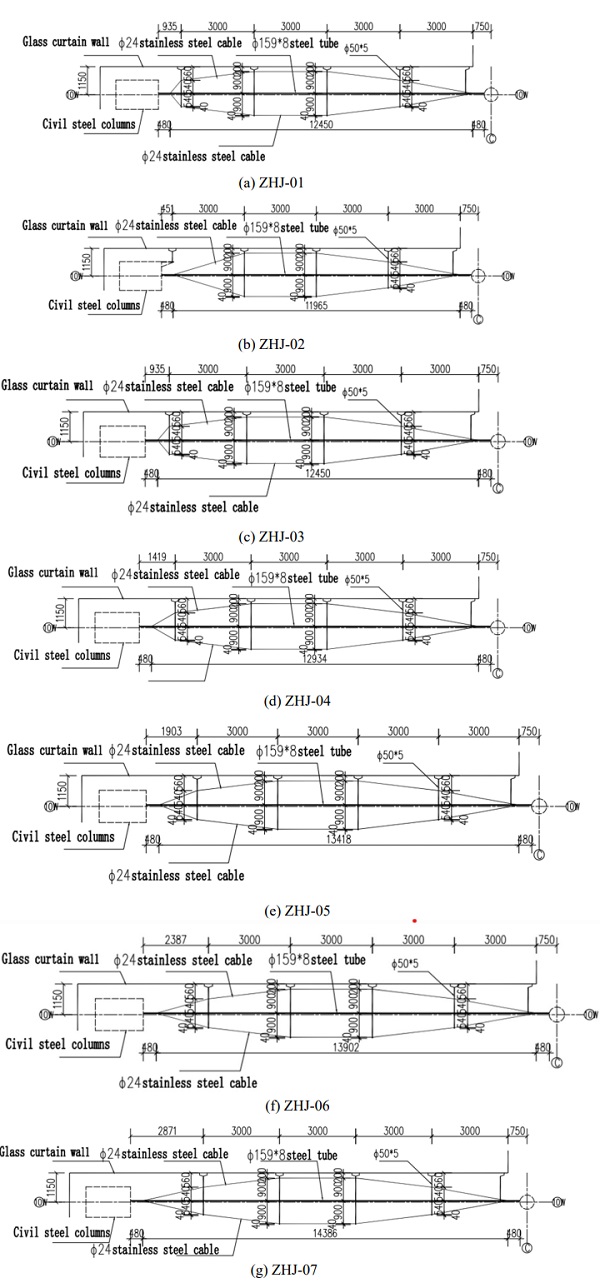
The curtain wall structure system was point supported glass curtain wall. Supporting structure was steel pipe structure, steel truss, and self-balancing cable structure point support. Truss and main concrete structures were hinged. Point support of the self-balancing cable structure consisted of two transverse cables, steel pipe, and stainless steel connector. Point supports of self-balancing cable structures of different floors were connected by vertical cables and tie rods to form an overall force system. The self-balancing cable structure point support was connected to the steel pipe structures on both sides. The glass curtain wall was fixed by the stainless steel connector. The glass curtain wall weight and other loads were transmitted to the cable structure point support through the stainless steel connector to achieve balance. The pre-tension of the cable was 50 % of the breaking force of the steel cable. The pre-tension was divided into three cycles: the first cycle completed 20 % of the pretension, the second cycle reached 80 % of the pre-tension and the third cycle completed the final pre-tension value. The size of the steel tube in the point support of the cable structure was 159 mm x 8 mm. The size of the transverse cable was Φ24. The size of the glass heavy cable was Φ16, and the truss gravity rod was Φ18. Transverse detail drawings of the self-balancing cable truss are shown in Figure .4.
3. SCHEME AND DIFFICULTIES OF GLASS CURTAIN WALL RECONSTRUCTION
3.1. Reconstruction scheme of curtain wall
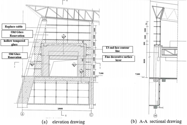
The renovation plan was to connect the corridors of Terminals T2-T3 and to open holes in the curtain wall. The size of the hole was 11780 mm x 9050 mm. After the opening of the T2-T3 corridor, it was necessary to add a door steel structure at the entrance. Moreover, the cable needed to be replaced to connect cable to door steel structure. Glass was installed after installation of cable. Facade and section of reconstructed glass curtain wall are shown in Figure. 5.
3.2. Construction difficulties of dismantlement
There are many difficulties in demolishing curtain wall glass. In the process of removing the curtain wall glass, to ensure the overall stability of the glass curtain wall, glass burst and collapse are not allowed. Due to the addition of the new channel, partial dismantlement and openings on the original curtain wall are needed. The original system will face the problems and difficulties that the original cable anchor self-balanced structure system is destroyed, a large range of curtain walls are dismantled and reinstalled, and the safety of the original support structure and the safety and reliability of the new support structure system in the dismantlement process.
There are difficulties in removing load-bearing cables. Because the cable could not form a stable structure in the relaxed state, it must be pre-tensioned to make it tense, so that the cable can resist the normal load. Dismantlement of load-bearing cables required reverse operation of the equipment to unload its prestress. Therefore, it is difficult to confirm a practical unloading scheme in construction.
3.3. Construction process
3.3.1. Removal of curtain wall glass
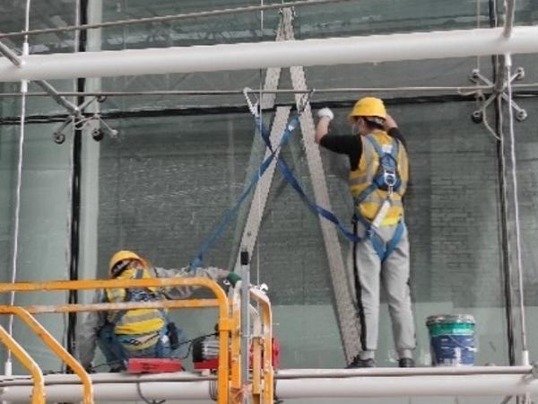
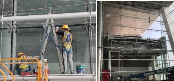
Firstly, the bolts between the lower part of the glass and the stainless steel connector were removed, the same to the connection between the upper part of the glass and the connector. Secondly, nylon ropes were used to pass through the hole left by the unmounted connector and bind together to hold the glass to prevent it from falling. Finally, the hoisting of parts is carried out by manual hoist, while the handling is carried out horizontally by manual suction cup. In the process of lifting the glass with a hoist, it should be ensured that the glass moved at a constant speed and was safely transported to the designated position. All the glass was removed according to this process. The site of glass removal is shown in Figure. 6.
3.3.2 Removal of vertical cables and pull rods
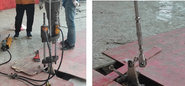
(1) Vertical cable was unloaded. When installing, the vertical cable was prestressed. When removing, it needed to unload prestress. A hydraulic jack was used to unload it. (2) The force exerted by the jack was checked through the panel and this step was repeated several times. (3) After each unloading, the tensioner was tensioned to the adjusting end. When the regulating sleeve is rotated slightly, turned the regulating sleeve in the opposite direction. (4) It was unloaded and operated repeatedly until the pin shaft at the cable ear plate could be extracted. (5) The vertical cable prestress was cleared and the connection between the vertical cable and the ground ear plate was removed. When there was no prestress in the vertical pull rod, it could be removed directly. This process was used to remove all vertical cables and pull rods. The removal process of the vertical cable is shown in Figure. 7.
3.3.3. Removal of lateral self-balancing point support with cable structure
The prestress of the cables was eliminated and the transverse cables were removed. The Pulley was installed on the upper crossbar and the lower crossbar was fixed with the pulley and the iron chain. According to the reserved position of the door hole, the crossbar was removed. The removed crossbar was carried down through the pulley and the manual hoist and was moved to the designated position. The first four layers of selfbalancing cable structure point support were removed. The removal process of self-balancing point support with cable structure is shown in Figure 8.
3.3.4. Installation of the door head of steel structure
The appropriate size of the section steel was selected. The relevant software was used for design and calculation to ensure the safety of curtain wall components under gravity load, wind load, earthquake action, temperature action, and displacement of the main structure. Due to span change, the original load-bearing cable and some of the tie rods could not be used. They all needed to be replaced and to recalculate the cross-section size of the cable and prestress value. The steel structure of the door bucket was welded with the remaining cross bars on both the left and right sides. The re-arranged vertical cables were connected to the upper part of the steel structure of the door bucket. When installing the vertical cable, the cable was hung from the top structure to make the cable free. After all the vertical cables were installed, the equipment was adjusted in the sequence from top to bottom, and the connectors were adjusted layer by layer.
3.3.5. Installation of curtain wall glass
The specifications of the original design glass remain unchanged. The original point support system, bar joint, and bar claw could be retained if they could still work. However, the remained parts needed to be retested. If these parts were deformed or the accessories are lost or worn seriously during disassembly, and the surface was severely corroded, they should be replaced. When lifting the glass, it should be firmly fixed with a packing belt and vertically lifted to the installation elevation by using the lifting point at the top of the channel. After installing the glass, protective tape was pasted on the glass on both sides of the glue seam to prevent sealant from polluting the glass and affecting the visual effect. Volatile cleaner was used to wipe the surface dust of silicone sealant to prevent leakage of sealant due to poor adhesion.
4. DYNAMIC MONITORING OF CURTAIN WALL DISMANTLEMENT
4.1. Arrangement of reference points
The point-supported glass curtain wall with cable structure was a complex stress system. During the construction of the removal process, with the unloading of the prestressed cable, the anchorage structure would deform, which would affect the interrelated cable force and the deformation of the curtain wall system. so it is necessary to monitor whether there is deformation in the areas with mutual influence.
The elevation system of the monitoring control network adopts the assumed elevation system. The elevation control network shall be arranged and designed according to the following principles: (1) The distributed control points form a control network, and the observation points and the associated control points form an extended network. (2) Control network and extension network should be designed as closed loop and node network attached elevation route. (3) The standard stone of the working base point could be buried by drilling. (4) After the sign was buried, it should reach stability before observation could be started.
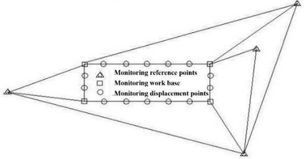
To ensure the accuracy and reliability of the position of the working base point in the horizontal displacement monitoring, the control points in the horizontal displacement monitoring reference network should be buried outside the deformation zone. The observation pier with a forced centering device should be constructed according to the deformation measurement accuracy (an optical centering device with a centering error of less than 0.5 mm can also be used). The layout of horizontal displacement reference points and working reference points is shown in Figure. 9.
4.2. Layout of monitoring points
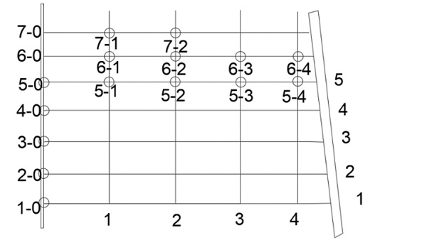
The arrangement of monitoring points was reasonably selected according to the needs of the project and the actual situation of the site. The monitoring points were arranged at the junction of each reserved connection structure to monitor the influence of the removed part on the reserved structure. Monitoring content was divided into anchor structure deformation monitoring and curtain wall relative displacement monitoring. Deformation monitoring of the anchorage structure was to observe the position in the plane of the fixed point in the anchorage structure before and after the cable was cut off to understand the deformation of the anchorage structure before and after the cable was removed. Curtain wall relative displacement monitoring was to observe the coordinates of the fixed measuring point of the curtain wall, mainly the deformation in the vertical and horizontal longitudinal plane. The layout of the monitoring points is shown in Figure 10.
4.3. Results of dynamic monitoring
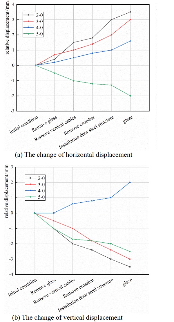
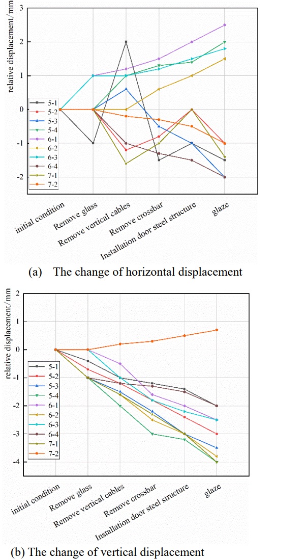
Monitoring points were marked with reflectors. During the measurement, the total station was set up on the control points of the established measurement control network. The data of the monitoring points were read from other control points to calculate the horizontal and vertical displacements of the monitoring points. The displacement of monitoring points under initial conditions was selected as a reference. The displacement of the anchor end of the cable and the displacement of the curtain wall structure in the stage of removing the glass, removing the vertical cable, installing the steel structure of the door, and installing the glass was obtained, as shown in Figure 11 and Figure 12.
As can be seen in Figure 11, the horizontal relative displacement and vertical relative displacement of the anchorage end of the cable gradually increased with the construction progress. The horizontal displacement of the anchorage end of the cable was increased by 2.0 mm ~ 3.5 mm, and the vertical displacement of the anchorage end of the cable was increased by 2.0 mm ~ 3.5 mm. The horizontal and vertical displacements of monitoring point 2-0 were the largest. there was a little change in the displacement of the cable anchorage end. The construction process had little effect on the cable anchorage end, and the cable was in a safe state.
It can be seen in Figure 12 that the increment in the horizontal displacement of the fixed measuring point of the curtain wall was 1.0 mm ~ 2.5 mm, and the increment in vertical displacement was 0.5 mm ~ 4.0 mm. The horizontal and vertical displacements of monitoring point 7-2 were the smallest. The change in displacement of the fixed measuring point of the curtain wall was small. The construction process had little influence on the fixed measuring point of the curtain wall, and the whole curtain wall structure was in a safe state.
5. CONCLUSION
With the rapid development of China's aviation industry, there would be a large number of airport terminals facing renovation. The construction technology of cable structure point supporting glass curtain wall dismantlement and reconstruction proposed in this paper had been successfully implemented in this project. It ensured construction safety and greatly reduced the cost of labor, equipment, and materials. Besides, it accelerated the construction progress. This research could provide a reference for the implementation of similar projects.
REFERENCES
- Yang J M. (2020) Research on construction technology of long-span curved cable glass curtain wall of Xiong'an Station. Railway Construction Technology, (009):000.
- Luo Y (2000). The engineering application on point flxing system of glazed building. Industrial Construction, 10:1-5.
- Li X F. (2007). Classification and component performance analysis of point-supported glass curtain wall support system. Journal of Building Structures, (S1):6.
- Wang J X, Qi L G, Yang M, et al. (2017). Combined Point-supporting Glass Curtain Wall with 55 Meters High Cable Net Construction. Construction technology, 46(18):3.
- Yang J Q (2022). Urban regeneration and sustainable development. Nanjing Southeast University Press.
- Duan W F, Zhang D W. (2017). Key construction technology of rhombic-arc-point styled glass curtain wall of optical valley international tennis center. Construction technology, 46(2):4.
- Zhang D, Wang L, Sun S X, et al. (2015) Research on construction technology of prestressed structure of Shenzhen Nanshan District. Construction Technology, 044(021):51-54.
- Wang X L, LI H J, Zhao C, et al. (2022). Key points of prestressed cable tension construction technology for cable curtain wall. Building Structure, 52(S01):4.
- Wang L B, Li A S, Huang L, et al. (2012). Construction technology of partial curtain wall nondestructive dismantlement of high-rise buildings. Building Technology Development, 39(11):3.
- Sun Z, Li S S, Li X C (2014). Sharing of construction technology for partial dismantlement of existing glass curtain wall at Changsha South Railway Station, a large-scale high-speed rail hub. Low Carbon World, (12 X):3.
- Hua Y Q, Liu Y, MA G X. (2022). Comprehensive construction technology for rapid dismantlement and renewal of glass curtain wall of super high-rise buildings. Construction Technology (Chinese and English), (015):051.


 demonstrator at Glass Technology Live during Glasstec 2024 (© Cas Maertens).")


