Source:
Challenging Glass 7
Conference on Architectural and Structural Applications of Glass
Belis, Bos & Louter (Eds.), Ghent University, September 2020.
Copyright © with the authors. All rights reserved.
ISBN 978-94-6366-296-3, https://doi.org/10.7480/cgc.7.4605
Authors:
Peter van de Rotten (Octatube)
Michele Arinze Akilo
Wouter van der Sluis

Since 2010, Octatube has adopted glass fins as structural components in at least 20 different projects, both in facades and roofs (the van Gogh Museum, the Tottenham Experience, Canal House Amsterdam are some relevant examples). Glass is widely known as a fragile material and it usually breaks in a brittle fashion, where as a metal like steel typically fails plastically. The post-breakage behavior of glass beams is not easy to predict, therefore Octatube performed a range of tests on different glass fins varying the test setup.
All tests were performed in house, at Octatube’s factory/test area in Delft, the Netherlands. In this paper two case studies are discussed. For the brand-new Spartherm Headquarters in Melle (Germany) laminated glass fins are adopted to support large insulated glazing units. Due to the round shape of the building the glass fins spanning for a maximum of 5.3 meters, are also curved on one side. The glass fins were tested both in un-cracked and cracked conditions to assess the overall safety of the design.
For the refurbishment of the National Gallery of Ireland in Dublin, a new glass roof, over the old Sculpture Courtyard, was designed by Heneghan Peng Architects. With glass beams up to 8.3 m, and 3x10 mm fully tempered PVB laminated panes were adopted. In cooperation with T/E/S/S engineering, the second support system was designed for post breakage behavior. In case of total failure of a glass fin, the safety was is ensured by catenary action in combination with a stiff frame of glass beam. This was tested in a true size, 6.0 meter, mock up. The residual capacity in the glass beam is ensured provided that the global structural system and detailing are carefully designed.
1.The Spartherm HQ case study
1.1.Introduction
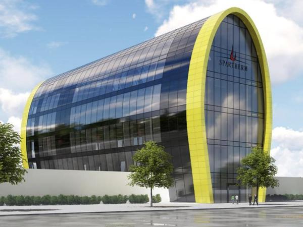
The new Spartherm HQ in Melle (Germany) features a bespoke glass façade composed of double insulated glazing units. The longitudinal silhouette of the building resembles the one of a flame and in combination with cold bent IGUs a transparent, aesthetically appealing and energy saving building is achieved. The northern and southern fronts are glazed with flat IGUs and complete the façade of the building. The main load bearing structure is composed of horizontal reinforced concrete slabs that define the floor plan at each level. Vertical and horizontal steel members connect the building skin to the concrete core.
![Fig. 1 Architectural impression of the Spartherm HQ in Melle [Artist impression: Station-D Architects, Architect of the project: Podufal Wiehofsky].](/sites/default/files/inline-images/Spartherm-hq.jpg)
At the top floor of the building, the primary load bearing structure for the façade and the external loads is obtained by a set of wooden arches. Horizontal steel hollow sections join the wooden beams to one another and also provide the supports for the glass fins. The fins are composed of laminated heat strengthened glass with a thickness of 10mm.
Between the glass sheets four PVB sheets are used. All edges are arrised and ground for safety and esthetical requirements. In order to guarantee structural redundancy to the whole glass fin package, a steel rectangular hollow section RHS 80 x 30 x 3 is connected to holes in the glass via two, three or four steel joints depending on the glass fin length (Figure 3).
Finally, cold bent unit with a bending radius up to 20 meters are installed on top of the rectangular hollow sections. The glass fins are supported at the edges by custom-made steel shoes welded on the side of the primary steel (Figure 4). Please note that due to budget cut, the glass fins design option has eventually been discarded and vertical steel hollow profiles have been adopted.
![Fig. 2a) and b) Architectural render of the wooden beamsat the building top floors and elevation drawing of the glass fins [Podufal-Wiehofsky, Octatube].](/sites/default/files/inline-images/Fig2_127.jpg)
![Fig. 3 Sizes and positions of glass holes in the fins. F1 and F2 are segmented on the load outer edge. Types F2 to F4 have a curved outer edge [Octatube].](/sites/default/files/inline-images/Fig3_115.jpg)
![Fig. 4 Glass fin F4, side view [Octatube].](/sites/default/files/inline-images/Fig4_114.jpg)
1.2.Test setup
The glass fins need to resist design loads up to about 18.5 kN distributed among holes in the glass. Since there exists no building codes or recognized standard that cover the design of laminated glass fins, an approval in the individual case (Zustimmung im Einzelfall, ZiE) is required by the German regulator to approve the construction method. Therefore, a test session is carried out at Octatube’s factory in Delft (the Netherlands) to assess the stability and the post breakage behavior of the glass fins under design loads in order to get final approval on the individual case.
Among four possible fin shapes in the project, two samples of the normative glass fin F4 (length = 5353 mm, height at center = 430 mm, height at ends = 300 mm) are tested both in unbroken and fractured state. Sample 1 is tested for loads acting along the positive X direction (see Figure 4). The following loads are considered: cold bending forces, permanent loads (cold bent glass unit, glass self-weight, the steel RHS weight is neglected) and wind pressure. The fin is placed horizontally, therefore all loads are carefully scaled down to match site conditions.
Sample 2 is flipped with respect to Sample 1 to simulate a load case that involves wind blowing in the negative X direction (wind suction). In this case, cold bending forces and permanent actions are counteracted by the ones from the wind and therefore the total applied load is lower than for the one adopted for sample 1.
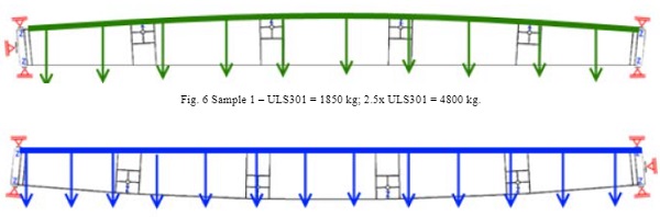
For both cases, the distributed loads are applied to the four holes in the glass fins by means of concrete blocks of about 500 kg each connected via a steel system. When necessary, extra concrete tiles weighing about 9kg each are added. A single steel frame is engineered to be able to carry out tests for both samples (Figure 5). All tests are carried out at room temperature of about 20°C.
![Fig. 5 Test setup drawings (TOP: Sample 1. BOTTOM: Sample 2). The concrete blocks shown are for illustration purpose only [Octatube].](/sites/default/files/inline-images/Fig5_117.jpg)
1.3. Loads
An overview of the load cases for each test is shown in Table 1.
- REP1: Cold bending
- REP2: Permanent load (Glass unit self-weight + Glass fin self-weight)
- REP3: Wind pressure (short term load duration according to DIN 18008-1)
- REP4: Wind suction (short term load duration according to DIN 18008-1)
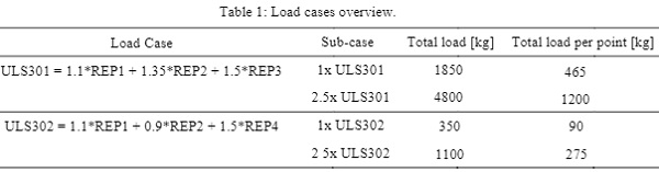
An extra load factor of 2.5 is applied to both load cases to simulate a buckling load multiplier. The glass fin said to be stable if no buckling is observed under the applied loads. Please note, the 1 x ULS302 test is not executed due to the resulting low loads on the fin.
1.4.Test results
A total load of 4800 kg is gradually applied on Sample 1 to simulate load case 2.5xULS301. An overall stable fin is observed under the loads. Furthermore, the unfractured glass surface proves that the proposed structural design of the fin (including detailing of the connections) is safe also from a strength point of view.
![Fig. 8 Sample 1 – 2.5 x ULS301 = 4800 kg [Octatube].](/sites/default/files/inline-images/Fig8_68.jpg)
Sample 2 should be tested under a total load of 1100 kg. However, the total number of tiles applied to simulate ULS302 is four and this results in a total load of 4 x 500 kg = 2000 kg. Also in this case and even with a higher test load, the fin safely withstood the buckling load without any signs of instability or visible damage on the glass.
![Fig. 9 Right, Sample 2 – 2.5xULS302. Left, lateral deflection under the loads is monitored via a displacement gauge [Octatube].](/sites/default/files/inline-images/Fig9_52.jpg)
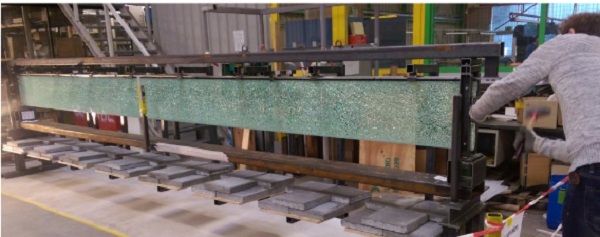
For Sample 1, the post breakage behavior under a total load of about 2200 kg is assessed. All three panes in the glass beam are manually broken in seven points after that the full load is applied. Under the effects of the static load, the cracks in the glass are observed to grow further from their origin causing a diffused crack pattern and concentrating the most in a particularly weak spot in the beam close to one of the holes (Figure 11).
The redundancy of the system is guaranteed by activating the secondary load path through the utilization of the steel RHS 80 x 30 x 3 connected to the top of the glass fin. In this way a ductile behavior of the system is achieved and a safe post breakage mechanism is possible as the beam gradually fails.
![Fig. 10 Sample 1 is cracked in seven spots along its length and all three panes [Octatube].](/sites/default/files/inline-images/Fig10_41.jpg)
![Fig. 11 Cracks in the glass fin during post breakage load test [Octatube].](/sites/default/files/inline-images/Fig11_33.jpg)
![Fig. 12 Sample 1 – Post breakage failure [Octatube].](/sites/default/files/inline-images/Fig12_27.jpg)
1.5. Conclusions
For a new building envelope in Melle (Germany), laminated fins made from heat strengthened glass are adopted as line supports for cold-bent insulated glazing units. In order to assess the safety and stability of the glass fin, a series of physical tests were carried out at Octatube’s factory in Delft (the Netherlands). The test session involved two samples of a 5.3 m long glass fin, supported at each end via two steel shoes and vertically loaded through four holes in the glass.
The level of prestress on the samples has not been measured, however the fracture pattern displayed in figure 11 suggests that the glass has been thermally treated. The tests were all performed at room temperature, both in unfractured and fractured situation. The tests with unbroken glass proved the safety and stability of the fins under loads up to 4800 kg.
The glass remained intact throughout the test duration. It is worth highlighting that the simulated load cases represent scenarios where the accidental leading action has a short term impact (wind pressure and wind suction), therefore there is a mismatch between the design loads and the actual test conditions where the weights are applied for a longer time (> 1 hour). This fact again proves the safety of the design and an overall positive test outcome.
Finally, sample 1 underwent a loading test where all glass plies in the fin were manually broken in seven spots. Under the effect of a reduced load (2200 kg), the glass fin gradually failed in a ductile fashion. This was achieved by introducing overall redundancy to the system via bolting a steel RHS 80 x 30 x 3 on top of the glass fin. Furthermore, the result showcased the importance of designing a structural system that also has a secondary load path to be activated in case of failure of the primary load bearing system. Also in this case, the test result is satisfactory.
2.The National Gallery of Ireland case study
2.1.Introduction
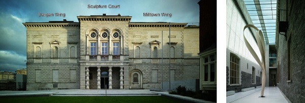
The National Gallery of Ireland (NGI) is located in the heart of Georgian Dublin, besides the Irish Parliament on Merrion square and adjacent to the National Library, Natural History Museum and National Museum. It houses the National Collection or Art and Irish Fine Art. The building itself has evolved over 150 years. The oldest wings are the Dargan Wing 1859 –1864 and the Milltown Wing of 1900-1903.
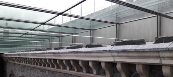
For the refurbishment of the Historic Wings, Heneghan Peng Architects designed a fully glazed roof for the Sculpture Courtyard. The space between Dargan and Milltown wings was originally intended as a lightwell and in the years blocked up and forgotten about in subsequent alterations. The new glazed roof light has turned this disorganized courtyard into well lit exhibition space, breathing new life into old spaces.
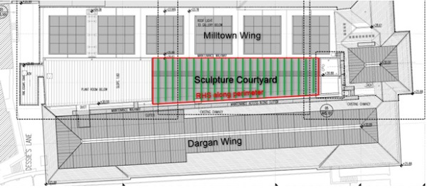
The dimensions of the roof are roughly 30x8 meter. The short span is covered by making use of 23 glass fins, which are the primary load bearing elements, varying in length from 6.8 to 8.3 m. These triple layer, 12 mm, fully tempered glass fins, have a maximum depth of700 mm and are laminated with 6 sheets of PVB (polvinylbutyral). The fins span between the old masonry walls of the Dargan and Milltown wing. The cladding consists of insulated glass panels connected to the fins with a dry glazing system.
2.2.Structural redundancy
During the engineering phase of the glass fin roof it was explicitly taken into account that glass may become damaged, by an unidentified hazard, during the life-time of the roof. Glass fins structures are always designed with structural redundancy, by creating multiple lines of safety for glass fin design. At the TU Delft different concepts of providing redundancy through the addition of steel profiles has been extensively researched at the TU Delft (Louter, 2011).
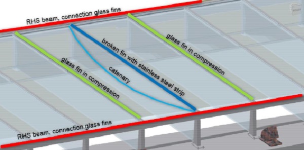
And extensive testing of glass beams with a range of different compositions under different levels of pre-applied damage has been performed (Bos. 2006). For this project a secondary load path has been designed, in cooperation with T/E/S/S, in case one of the glass fins experiences a three-sheet fracture. In case of complete fracture the glass becomes a suspended structure since a catenary line is formed between the glazing support profiles. The catenary forces are transferred in-plane to the fins adjacent next to the broken fin.
There are different lines of safety:
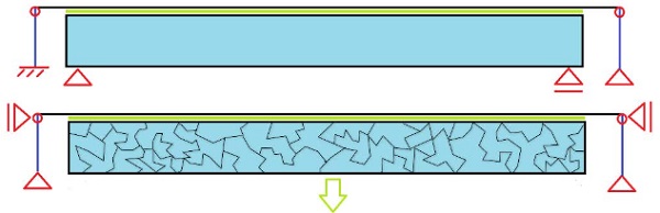
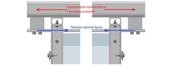
- Residual capacity in the strength of the material – no glass sheets broken: Under normal circumstances, the glass fin transfers all vertical loads to the supports. The fin shoe on the left side provides horizontal support, since the bottom is fixed. At the top of the fin shoes, the glazing support profile is hinged.
- Lamination of the glass fin – one glass sheet broken:See Fig 16. The glass fin is actually a laminated pane with three separate glass sheets. If one sheet is damaged, there are always two additional glass sheets which are capable of carrying the applied forces on the fin.
- Lamination of the glass fin – two glass sheets broken: See Fig 16 and 17 In case two separate sheets are damaged, the fin is still required to remain structurally safe. The fragility has shown that the fin is able to carry at least the self-weight of the glass and the superstructure.
4. Secondary load path–all sheets are broken
The last line of safety is formed by the secondary load path of the structure. Although three broken glass sheets in one glass fin is an extremely rare condition, this special situation was well-investigated by Octatube, both with computer models and by true size testing in the workshop. Since the glass is broken, it is merely suspended on the superstructure.
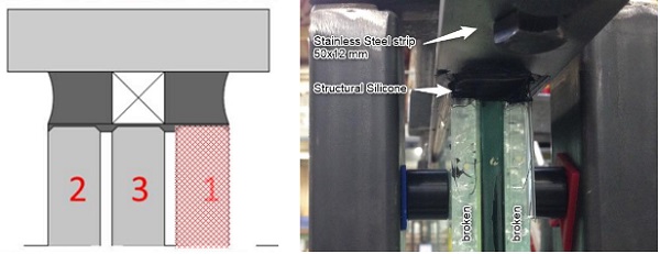
The superstructure consists of a steel strip, on which the glass is sealed, and is mechanically connected to the RHS, S355 200x100x10 mm. The flexible stainless steel strip, 50x12 mm AISI 316,is able to form a catenary (very similar to a laundry line). The steel structure, with the RHS along the perimeter, and the adjacent glass fins are used to close the secondary load path. See Fig 15. In order to reduce the risk of the glazing units sliding of the glass fins the maximum allowable deflection using the catenary mechanism is set to 300 mm.
When the glass breaks the glazing support profile deforms due to the load, then the vertical load is transferred to the bolted supports at the ends. This results in a tension normal force in the stainless steel strip, a horizontal reaction force (directed outwards) and a vertical reaction force (directed upwards) at the supports. The horizontal force is carried by the subsequently described system in the following section. The vertical force is carried by the support structure through the fin shoes as a normal force.
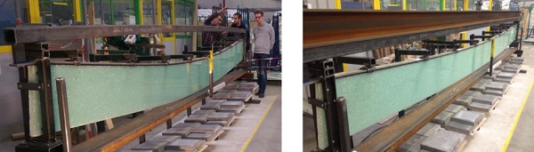
2.3.The test set up
A physical large scale test was requested to demonstrate the safety of the proposed system. The fin is loaded with the full dead load and 20% of the live loads. The goal of the experiment and calculations is to verify the structural integrity of the glass fin and the support structure after fracture due to an un identified hazard. Several situations will be checked under a predefined load. However, in this paper the fracture of all 3 sheets is enlightened. In case of three broken sheets, the support structure must form a catenary line, the support structure must have sufficient carrying capacity. While no dangerous glass fragments are allowed to fall from the laminated glass.
It is aimed to closely relate the experiment to the fins in the situation in which they will be built. The same conditions will therefore be created, how ever the size of the fin and the thickness of the sealant has been reduced.
The test fin has a length of 6000 mm, a height of 400 mm and sheet thickness of 10 mm. The glass fin consists of three sheets, fully tempered glass, which are laminated with 6x0.38mm of PVB as interlayer. The strip has been sealed on the glass fin using a structural sealant, Dow Corning 895. To equally space the steel strip on the fin, foam tape has been used with a height of t=10mm, the sealant has a width of 10 mm per side and a thickness of 10 mm.
The dimensions of the stainless steel profile are 50x12mm, AISI 316L is the quality adopted. The total length of the profile is 6250mm, where the profile protrudes 125mm at both ends of the glass fin. Short slotted holes, parallel to the fin, are made in the profile to allow for a small initial deformation. This enables the formation of the catenary.
2.4.Loads
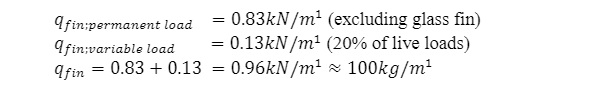
This load is placed on the fin using several point loads, which are equally spaced along the fin length. The point loads are made by suspending concrete tiles on the glass fin. The fin is loaded with an equally distributed line load of 100kg/m. In the experiment, the distributed load will be simulated using several equally spaced point loads, which are applied at the top of the fin. In the experiment, the load is applied before the sheet(s) are broken.
2.5.Computational model
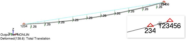
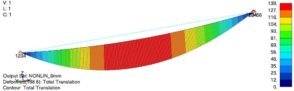
For the test a simplified numerical calculation has been carried out. The FE model consists of a single ‘beam’ element, with geometrical and mechanical properties of a 50x12 mm stainless steel strip, two sided supported. On one side a gap element of 6mm has been introduced, to simulate the slotted hole present in the test setting.The total linear load applied to the beam element is 1.26 kN/m (including glass fin weight). A non linear large deflection calculation was performed.
A deflection of 139mm results from the performed analysis and it describes the system response in case the glass fin has no load bearing capacity after all glass plies are broken. The full weight of the glass fin is supported by the catenary. The system response to the GAP element introduction is quite sensitive. For comparison, a FE model of the stainless steel strip without the GAP element, deflects vertically by 93 mm.
2.6.Test result
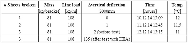
The deformation of the fin after breakage of the third ply, was instant. After the first deflection a small additional deflection was observed. The total deformation was 182mm, where 140mm was predicted with an FEM model, which is not discussed in detail in this paper. The RHS80x80x8 section deflects upwards due to the bending moment. This leads to additional deflection of the glass fin because the supports moved inward. After applying a much stiffer HEA profile on top of the SHS, the deflection of the glass fin was only 135 mm.
The beam was left standing for a week. During this time period, no additional deflections were measured.
2.7.Conclusions
The catenary line was formed:
It was predicted that a mechanism including a catenary line would appear. This was indeed the case. The predicted deflection was different from the observed deflection. It is only possible to estimate this deflection, since the stiffness of the surrounding structure has to be estimated. This is not problematic for the system, since a higher deflection exerts lower horizontal forces on the support structure.
No dangerous glass fragments fell from the laminated glass fin:
The observed fragments are not dangerous for people happening to stand under the glass fin when full fracture occurs, as the maximum fragment size was in the order of 1 or 2mm.
Final conclusion: The proposed system including the sealed glazing strip is safe under the circumstances that have been described. The circumstances in the Sculpture Courtyard are structurally equal in carrying capacity.
3.References
DIN 18008-1:2010-12 –Glass in Building –Design and construction rules – Part 1: Terms and general bases (2010-2012)
P.C. Louter, Fragile yet Ductile: Structural Aspects of Reinforced Glass Beams, Doctoral Thesis, TU Delft(2011),ISBN 9789085707431
F.P. Bos, Safety Concepts in Structural Glass Engineering: Towards an Integrated Approach, Doctoral Thesis, TU Delft(2009), ISBN 9789085704287