First presented at GPD 2019
In the world of glass -especially within the structural glass use- it is normal to see big projects, with huge budgets and big specialist companies involved, as the glass cube. However, thanks to this kind of projects, the technology is moving forward, and little projects with clear concepts can be developed.
The main issue in all these projects is to maintain the main concept at every level: architecture, structural and constructive. Once these concepts are clearly defined, and without other elements, it is easy to obtain great results with low economical effort.
The Arturo Soria lobby is one of these projects, holding a clear architectural and structural scheme without other interactions. The project is the extension of an existing lobby, to grant new access requirements, stepping into the existing courtyard and creating a bigger space with more light and transparency, in a direct relation to the landscape.
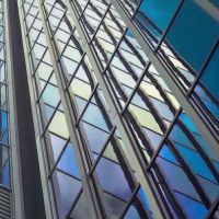
For this reason, all the enclosure has been made of glass, avoiding structural massive elements that do not allow this transparency. The enclosure is composed of a vertical façade with a free design, and a horizontal skylight, all in glass.
To avoid massive structural elements, the horizontal glass skylights are supported by the vertical glass façade. The skylight is supported by horizontal fins, fixed on one end to the building and on the other side to a steel beam spanning through the whole dimension of the courtyard.
This beam is connected in its lateral edges to the building slabs, but in order to minimize its dimension, a new support is placed in the middle, over the vertical glass façade pane. To avoid the buckling of this element, two vertical glass panes are situated on both sides, perpendicularly, and fixed with structural silicone. In order to guarantee the load transmission in the correct way, some special steel fittings are installed within the enclosure.
The structural and architectural concept is clear, and all the requirements are conditioned by these concepts. A small local construction company was able to tackle the challenge of the construction, avoiding the use of façade or glass specialist sub-contractors, reducing to the limit the final construction cost.

Introduction
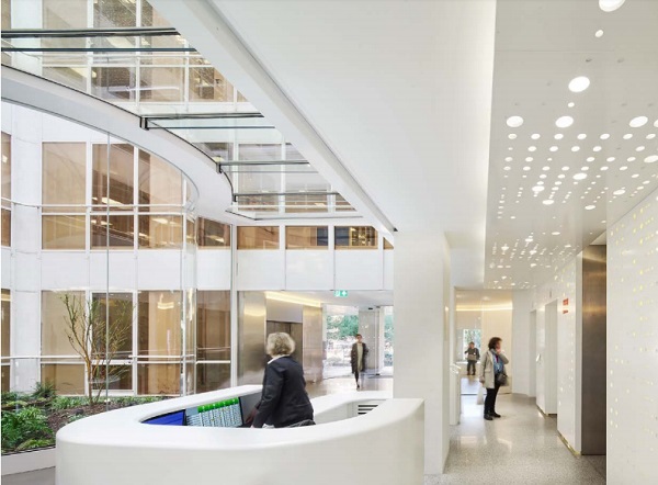
This intervention in an office building aims to blur the limits between interior and exterior space, with a glass pavilion designed with curved geometries that merge with the garden creating a new fluid and hybrid landscape. The access is transformed into a new experience interior and exterior melt together.
The proposal was the winning entry in a restricted competition with a design & build format -which is not very common in Spaintherefore implying concept and construction (integrating architects, engineers and general contractor). The owners wanted to increase the value of the property, built in the beginning of the 90’s in the north of Madrid. The main challenge in the brief was to update the obsolete access space, meeting all the new access requirements and solving the existing functional problems.
But the real challenge in the project was to actually build a strong concept working with three very restrictive premises:
• The office building must keep its normal functioning during the works, which makes the planning a key issue.
• It is necessary to integrate and coordinate other renovation works in the building such as the landscaping, the elevators renovation and other actions in the different halls in every floor. That requires an understanding of all the works as a total intervention.
• Last, but not least, the most restrictive premise was the total budget of the project. All the works, including the project and the construction, must be ca. 620 €/m².
Since the Modern Movement, the development of new technological solutions has given architects a huge freedom to design, with virtually no restrictions, but the challenge is still the same as it was in the primitive cabin of abate Laugier –to manage the relation between man and nature, to obtain protection from the exterior and control the environment conditions. Many projects, in absence of any restrictions, use big budgets and every available piece of technology. This project, on the contrary, shows that strong and complex concepts and advanced technical solutions can also be undertaken within tight budgets, using conventional production systems.
Architectural Concept
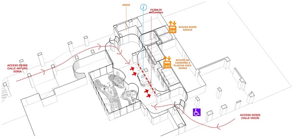
The existing building had several access problems. The main entrance was barely used and was not accessible for PRM. Most people used a little service entrance in the opposite façade of the building, on the other side of the elevators’ hall. The public desk was near the main entrance and had a difficult sight on this secondary entrance. Moreover, the new requirements for access control implied the installation of turnstiles.
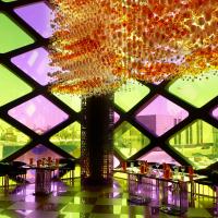
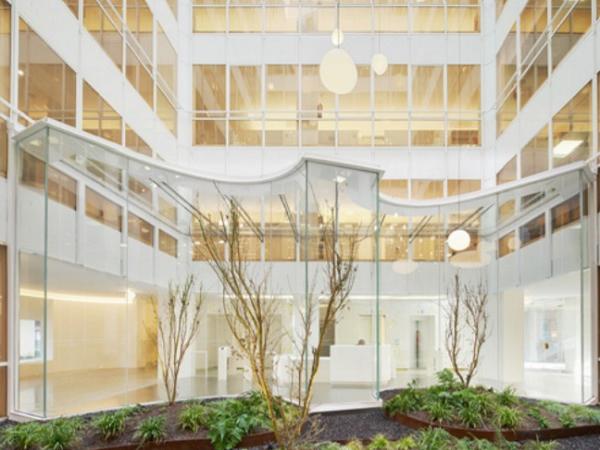
Taking advantage of a remnant plot ratio allowance, the only possible strategy was to blur the limits of the access floor stepping into the patio, solving all the functional problems in one gesture. The proposal materializes into a glass pavilion with curved geometries that blends with the garden in a new hybrid space. Curves favor a dynamic and continuous perception of the space and define gentle and organized spaces.
In this way, the design avoids any horizontal and vertical opaque elements. This together with the mentioned curved geometries and the transparency and reflections of glass help blurring the boundaries between inner and outer space.
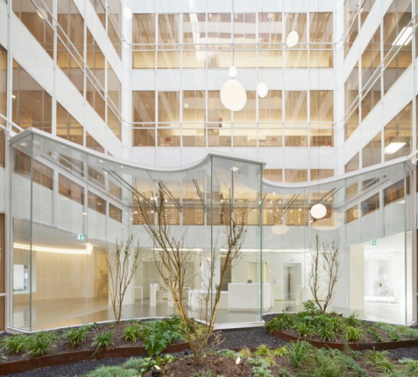
The patio, that was almost hidden in the previous scheme, is revealed as the most attractive element in the building. Integrated with the geometries of an ongoing landscaping project, the 4,5 m high glass Pavilion allows the connection of the two entrances, centralizing the movements and integrating the patio in the building.
A new frontal main access to the elevators hall allows to distribute the required turnstiles on both sides of the new public desk, located in the center. The new lightning in the patio, rising to the roof, gives more verticality and unifies the pavilion with the rest of the levels playing with crossed views, lights and reflections.
The aim of the proposal is to refurbish the space, but it is not simply a renovation of all the materials. As a matter of fact, maintaining some existing materials, like the granite floor, allows to accomplish the budget objectives. Instead of the standard tabula rasa approach, the proposal sheds a new light into the existing elements integrating the new and the old (for instance backlighting the green glass below the new perforated panels).
Structural concept
The structural sketch is very clear. The main structural element is a new steel beam situated between the vertical façade and the horizontal elevated skylight. This beam and the other elements are supported on the existing structure, mainly over the slab of the first floor. The skylight is supported in the perimeter by the existing structure and the new beam. The vertical façade is supported on the lower slab, but it is stabilized on the top with the new beam for the horizontal loads.
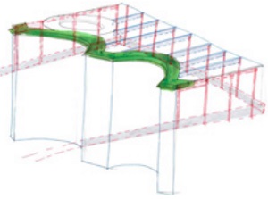
The skylight is composed by transversal beams in the slope’s direction, supported exclusively on both ends: on one side over the actual structure and on the other side over the new structural beam.
The position of the skylight does not coincide with the height of the structural slab, because the skylight must meet the horizontal transom of the existing windows, which is one meter above the slab. For this reason, it is necessary to include vertical corbels to adapt the difference between heights.
These brackets, made of lacquered steel, are fixed over the front of the slab with a three-dimensional regulation in order to obtain the horizontal line on the top. These vertical elements are in the same position as the mullion of the existing building, to integrate them in the design.
The fixing between the beams and the brackets is made with only one screw that allows rotations but fixes the movements.
On the other side, the beams are supported on the new beam with the same system, but in this case a horizontal hole is situated in the beam in order to guarantee the longitudinal movements of the beam due to thermal expansion.
The new beam is supported on both ends over the existing structure. Just as the skyligth beams, the new frontal beam is 1,5m higher than the structural slab and it is necessary to include some brackets to reach the new level.
In this case, the position of the new beam is in the middle of two mullions, and therefore it is necessary to include a horizontal beam between these two vertical elements to connect the new beam, acting as a little bridge. In this horizontal brace, a steel perpendicular element receives the end of the new main beam. In one of the edges the joint is free to let thermal movements.
To avoid an important impact on the existing glass facade of the first floor, it is necessary to reduce the height of the new beam. This beam does not have problems with the horizontal dimensions, and therefore its depth is enough to support the horizontal loads without any other support.
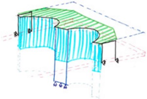
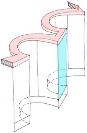
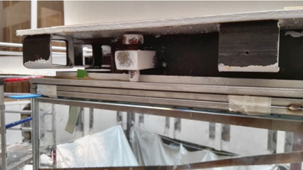
But its vertical dimension couldn’t be more than 170 mm. With this height, the distance between supports (10,00 m) and the vertical loads, the beam has an elevated deflection, which implies visual problems and water penetration. For this reason, it was necessary to introduce a vertical support in the middle of the beam.
This support is made with a vertical glass pane of the façade. This glass is prepared to receive the vertical loads of the skylight, so it is thicker than the rest of the façade glasses. In order to avoid the buckling problems of this glass due to its slenderness, this glass is glued with structural silicone to the lateral glazing units, that are situated perpendicularly, giving additional stiffness to the enclosure.
Constructive concept
All the elements of this façade are made with glass, lacquered Steel and stainless Steel.
The vertical façade cladding is composed of single glasses from the bottom to the top. Some glasses are curved and others straight, all of them laminated composed of two panes of 12 mm and 2 layers of PVB, except for the central structural glass. These glasses are supported in the bottom and stabilized on the top. The support is composed of a Steel component that allows the vertical adjustment of the glass to guarantee its position.
This element is made by two vertical steel tubes, and one horizontal plate that can move between the steel tube. To fix the horizontal movements a steel plate with the shape of the enclosure is situated in the exterior and the interior side. This plate is screwed to the vertical steel tubes. In the exterior part this plate has another L profile to guarantee the watertighness with the external joint.
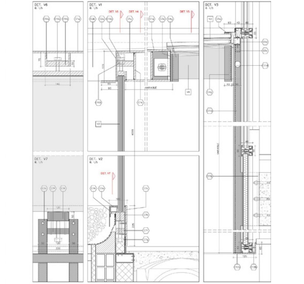
In the top assembly, the glass is supported on the steel beam, allowing the vertical movements, while on the exterior a horizontal bead is situated with an “L” shape, screwed to the interior steel beam.
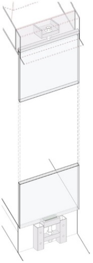
The glass in the middle supports the upper beam and the skylight. For this reason the glass is thicker than in the rest of the facade. In this case, the glass is composed by three panes of 12 mm glass with 2 PVB between every glass pane. To ensure the support of the glass on the top, a steel screw is fixed between the glass and the beam.
In the skylight system, the glass beam is composed by a laminated glass of three panes of 12 mm tempered glass, with a stainless steel “T” profile glued in the top in order to support the horizontal glass of the skylight. The horizontal glass of the enclosure is composed by a double glazing.
The exterior pane is a 8 mm exterior tempered glass with a solar control coating in face 2, and the interior pane is a laminated glass composed by two panes of 6 mm with 2 PVB. In between the two layers there is a gap with Argon to obtain a better thermal behaviour and to avoid the interior condensation.
These horizontal glasses have in the perimeter glued an “L” shape profile of stainless steel in order to guarantee that the surface is watertight. This profile overlaps with an external cap made of stainless steel, with an “U” shape, that blocks water infiltration.
In the joint with the existing building this “U” profile is changed with an “L” profile fixed to the existing frame, but also overlapping the “L” profile of the glass. In this area, in addition to the “L” shape profile, an EPDM membrane is glued between the different elements to have two barriers against water penetration.
In the exterior side of the skylight, between the glass and the new beam, an overlapped solution is made esto no se entiende. In this case, the upper glass of the double glazing overlaps with the steel beam to allow the flow of the water over it, avoiding water penetration.
On the transversal beams a steel rod is situated between the “L” shape profile of the glass and the “T” shape profile of the beam in order to fix both elements.
Construction process
For construction there were two important subjects:
• Total Budget
• Maintaining the whole building functioning at a normal pace
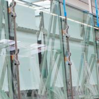
Due to these requirements the main works were to be undertaken during the summer. T In order to have prepare all the materials for the installation, the fabrication must be made based only in the drawings, it is not possible to have measurements on site, mainly the glass, because the fabrication time of curved glass is very long. To ensure that the dimensions of these glasses, some Wood templates were made and sent to the different factories (glass and steel), in order to guarantee a perfect assembly. All the elements, glass and steel were laser cut, and they were installed with topographical control.
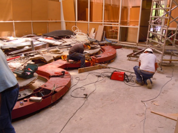
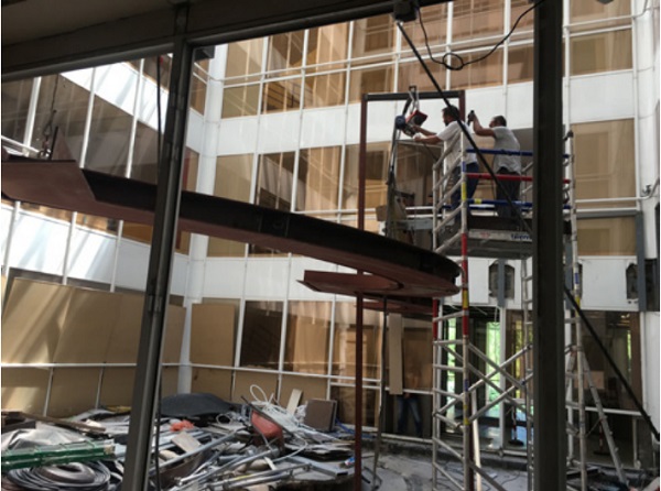
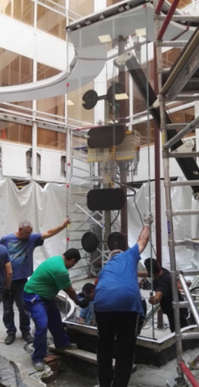
One of the most difficult actions during the installation was the correct placing of the main beam. The beam, 10 m width, was fabricated in 3 different pieces with different geometries, and should be assembled and welded on site, maintaining the total geometry of the beam. The setting out and welding was made on the floor, with the help of topographical instruments, and then the total beam was elevated to its position with 2 tackles situated in the ends of the beam, keeping the horizontal level of the beam through the whole process, to avoid deformations.
Before the elevation of the beam took place, vertical brackets were positioned on the structural slab coinciding with the existing windows frame. When the horizontal beam was placed, the ends were fixed over the previous brackets. To maintain the level of the beam until the installation of the vertical glass, some provisional post were situated in the middle.
Once the beam was properly placed, the horizontal support of the glass in the bottom was installed with the same geometry of the upper beam, to keep the vertical alignment of the glass enclosure.
Two sets of identical templates made in wood were sent to the glass manufacturer and the steel company, to make sure that both would fit on site. This allowed us to shorten the fabrication process.
With both the upper and lower structures in place, the most difficult action was undertook, loading the vertical glass. For this action the vertical screw on top of the middle glass was tightened to make contact with a horizontal stainless steel plate placed on top of the glass. This stainless steel plate was levelled over the upper edge of the glass with a self-leveling resin of Hilti with High strength. This resin allows the homogeneous distribution of the load all over the glass. When the screws were situated, the vertical tackles were removed and then the installation was concluded.
After positioning every structural element, the transversal beams of the skylight were installed with the horizontal screws, followed by the installation of the horizontal glass of the skylight.
At last the vertical glasses were installed between the bottom support and the upper beam, with the interior and exterior lacquered steel beams. The vertical glasses were sealed –the structural vertical glass, in particular, to avoid the buckling of vertical glass.
This sealing was made with structural monocomponent silicone of Dow Corning to be applied on site. This structural silicone was selected in grey color to minimize visual impact in the glass façade. The other sealings were made with watertight transparent silicone, and in the top and the bottom with black watertight silicone.
Conclusion
As a result of the processes involved in the project and the construction of the pavilion we learn some lessons:
• It is not necessary have a big budget to obtain big architectural results
• It is fundamental to know the way of construction while designing and developing the project, in order to adjust the constructive designs and technical solutions.
• The result of the project is better if all the people involved are engaged with the same objective.
• To obtain better results it is necessary that every element is designed at the beginning of the project.
• It is the development of technological solutions in big projects with big budgets, that might allow little projects to incorporate these technological improvements.
Acknowledgements
Photographs by José Hevia.