Challenging Glass 6
Conference on Architectural and Structural Applications of Glass
Louter, Bos, Belis, Veer, Nijsse (Eds.), Delft University of Technology, May 2018.
Copyright © with the authors. All rights reserved.
ISBN 978-94-6366-044-0, https://doi.org/10.7480/cgc.6.2178
Author:
David Bott | Heintges Consulting Architects & Engineers

Sarah Oppenheimer is an artist whose work with glass challenges our perception of space. David Bott (PE, SE, AIA) of Heintges Consulting Architects & Engineers assisted Oppenheimer in developing structural solutions that do not always conform to traditional architectural parameters, often when there are no precedents in building codes. Bott highlights the apparent lack of clear glass engineering guidance in both the International Building Code and the ASTM E1300 standard. He goes on to explore the importance of utilizing information hidden deep within E1300 or contained in other codes andglass engineering literature, to tackle unique structural design situations.
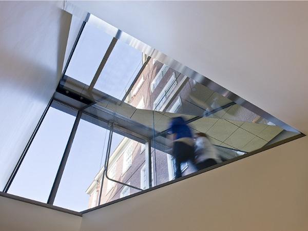
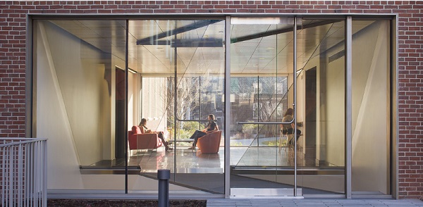
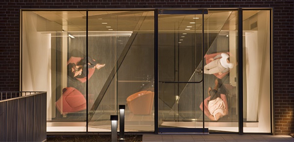
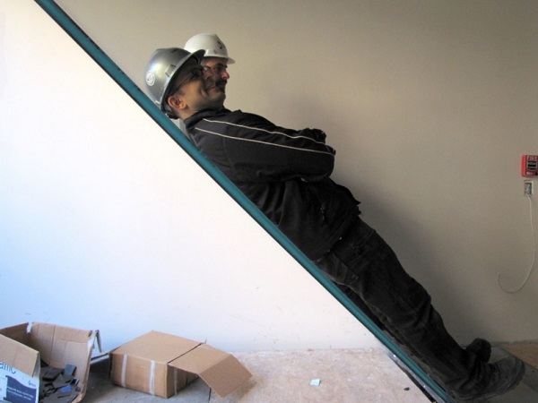
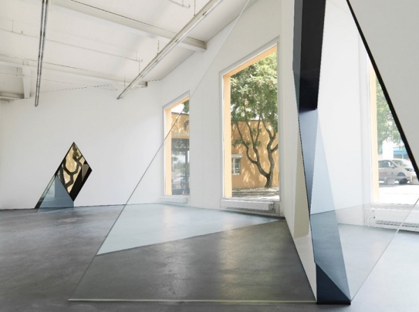
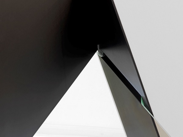
Engineering experience and imagination are not only relevant, but required. Two Oppenheimer projects are presented illustrating how the engineer overcame unusual structural challenges to help the artist develop her installations. The first project, a permanent entryway sculpture entitled P-131317, primarily consists of two oversized lites of glass sloped at 45 degrees, between which occupants enter and leave an academic building. The second project, a temporary gallery installation entitled 33-D, comprises two trapezoidal sheets of glass mounted through openings in the gallery’s partition walls. The bottom edge of each angular glass litefloats just above the floor plane with only three minimal support points.
1.“Glass breaks.”
“Glass breaks,” is a statement acknowledging the obvious fragility of the material, but because “glass breaks,” we are certainly challenged as structural engineers to design with glass in a manner consistent with the same standards of safety and care we would employ using any other more traditional building material such as concrete, steel, or wood.
Although some guidelines for glass design and engineering exist in current codes and standards, they are typically intended for design and analysis of glazing systems. For less conventional uses, the guidelines are often buried in the latter chapters of code, or hidden in the appendices or commentary of referenced standards. Of course, glass structures that require more unusual uses of the material are uncommon, primarily due to scarcity of qualified fabricators, high construction costs, or even client fear. In addition, glass is not a traditional structural material addressed in standard engineering curricula. No wonder the guidelines necessary for glass analysis are not at the forefront of code, and why many engineers shy away from the material.
2.Glass in the International Building Code
Chapter 24 of the primary building code used throughout the United States, the International Building Code (IBC), is called “Glass and Glazing.” This chapter includes the basic guidelines necessary to design typical glass windows, skylights, and railings, including rules regarding safety glazing applications. The chapter also heavily references ASTM E1300, which is entitled “Standard Practice for Determining Load Resistance of Glass in Buildings.” This standard not only provides simple methods to determine allowable pressures and deflections of conventional monolithic, laminated, and insulating glass with 4, 3, 2, or 1-sided simple edge supports, but also includes appendices (considered “nonmandatory information”) with additional resources to calculate the structural capacity of glass in general, taking into account heat treatment, edge condition, load duration, and probability of breakage.
Because the appendices are considered nonmandatory, utilizing the ASTM E1300 standard has apparent limitations when glass does not conform to traditional architectural parameters (e.g. Non-rectangular glass plates, bent glass, glass with atypical support conditions, structural glass, etc.):
- 1.2 This practice shall not apply to other applications including, but not limited to, balustrades, glass floor panels, aquariums, structural glass members, and glass shelves(ASTM E1300-12a).
Nonetheless, the E1300 appendices include guidelines to determine allowable glass stresses when using glass in the apparently restricted applications noted above. Moreover, the IBC addresses these unique circumstances through the following references:
- 2403.2 Glass supports. Where one or more sides of any pane of glass are not firmly supported, or are subjected to unusual load conditions, detailed construction documents, detailed shop drawings and analysis or test data assuring safe performance for the specific installation shall be prepared by a registered design professional (IBC 2015).
- 2404.4 Other designs. For designs outside the scope of this section, an analysis or test data for the specific installation shall be prepared by a registered design professional (IBC 2015).
- 2409.1 Glass walkways.(first referenced in 2015 IBC) Glass installed as a part of a floor/ceiling assembly as a walking surface and constructed with laminated glass shall comply with ASTM E2751 or with load requirements specified in Chapter 16(IBC 2015).
It is clear that for specialized glass design and engineering, the IBC and ASTM E1300 are starting points, and the services of a structural engineer are required – but what does an engineer need to know to confidently design glass structures?
3.The Glass Engineer
The engineer must be familiar with the material properties of glass, including its structural properties as well as its dimensional tolerances and fabrication limitations. The engineer should understand the various processes involved in glass fabrication, such as heat-treating, laminating, and coating, and their impacts on structural performance. Theengineer should be aware of the mechanisms of glass failure and post-breakage strength and stiffness characteristics. He or she should understand how edge treatment, load duration, and temperature can impact glass strength and stiffness.
Where applicable, the engineer should be familiar with redundant design of glass structures to ensure that failure of glass does not lead to loss of structural integrity. The engineer should also have experience in the design of connection details, which is equally important to the design of the glass members themselves. Finally, the engineer should be confident. “Glass breaks. So what?” A properly engineered (and fabricated) glass structure can break; it must not cause harm. Note that proper glass fabrication is just as important to structural integrity as proper engineering – but this is a topic for another time.
To supplement the nominal glass engineering guidance found in the International Building Code and ASTM E1300, the glass engineer should rely on experience and additional resources found in other codes and glass engineering literature.
4.Glass Engineering Literature
A prime example of a glass engineering guide that includes a variety of topics necessary for the successful design of glass structures is Structural Use of Glass in Buildings from the Institution of Structural Engineers. The text is a useful complement to IBC and ASTM E1300 and covers the design and analysis of glass beams, columns, floor plates, and connection details, among other topics. It also includes calculation examples and references to other glass design standards. The guide can serve as a broad resource for new and experienced glass engineers faced with less traditional design situations involving glass. That said, as with building codes and standards, the guide will not necessarily explain how to anticipate the appropriate design loads to apply to a unique structure.
When designing glass structures for wind, snow, or floor live loads, the local building code will typically provide guidance for load derivation. Loads for more specific cases, such as blast resistant design of glass, may be prescribed by a security consultant. In situations where no precedent for the design exists, the determination of proper design loads and the tolerable risk of failure requires serious thought and often a bit of imagination.
5. Glass as Art
When Sarah Oppenheimer, an artist who uses glass extensively in her work, approached our firm to assist her with developing new projects, we were immediately confronted with the task of designing and analyzing unique glass structures that could be subjected to unusual loading conditions given the nature and context of the installations. Here we explore two of Oppenheimer’s projects that are particularly well-suited to highlight the unusual glass engineering attributes of her designs.
5.1. P-131317
At the Metcalf Building on Brown University’s campus in Providence, Rhode Island, stands Oppenheimer’s permanent entryway sculpture entitled P-131317. Her exploration of perception and architecture perfectly complements the research housed at Metcalf’s Department of Cognitive, Linguistic and Psychological Sciences. The installation primarily consists of two oversized trapezoidal lites of glass sloped at 45 degrees, between which occupants enter and leave the building. By removing sections of the floor below the inclined, semi-reflective glass and creating new sightlines to the basement and the lobby, the artist forms an architectural illusion. Beautifully, the work changes as light levels shift throughout the day.
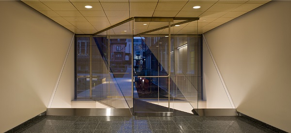
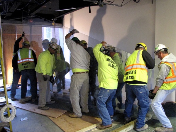
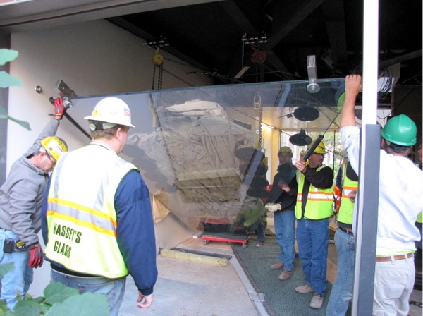
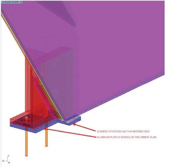
We collaborated with Oppenheimer to design and engineer the triple-laminated trapezoidal glass and connection details. The two primary glass elements, which span diagonally from the lobby level to the second floor above, act as both a roof for the basement and a guardrail for the lobby. The glass effectively prevents occupants in the lobby from falling into the basement below. Looking to the building code for guidance, it is difficult to determine if the glass should be designed as a skylight, a guardrail, or both. In either case, the glass would be fully tempered for strength and laminated for safety. Heat soak testing of the glass would also be required to reduce the chances of spontaneous breakage due to nickel sulfide.
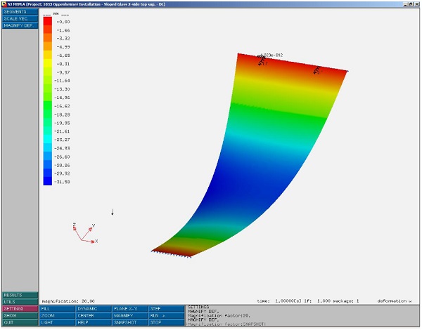
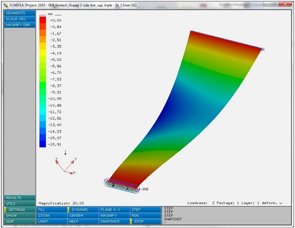
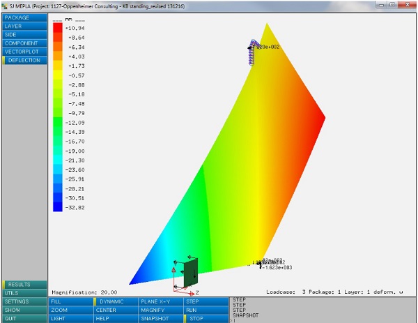
The trapezoidal shape and long, unsupported span of each lite do not conform to typical glass design guidelines found in ASTM E1300. In addition, the support conditions, including fixed bases to minimize glass distortion under self-weight, required more detailed analysis. We addressed these issues using SJ Mepla, a finite element analysis software developed especially for glass, to study the stresses and deflections of the glass under anticipated loads.
Glass installation was made possible by dedicated steel beams in the ceiling above the glass, from which the lites could be temporarily suspended prior to permanent placement. The beams would then remain in place, to allow for future glass replacement in the unlikely event of a break.
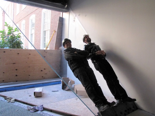
When contemplating worst-case loading scenarios for the glass, we could not ignore the possibility that enthusiastic college students may want to “test” the glass with their body weight. The scenario we envisioned accounted for several students laying down on each trapezoidal lite of glass at once. In addition to designing the glass to support this kind of live load, we treated the installation as if it were a guardrail designed to support a load of 0.73 kN/m at a height of 1067 mm above the floor. Furthermore, we incorporated a sacrificial lite of glass into each laminated assembly to prevent collapse even if one lite were to break under a late-night “college” load. And just to be safe, after initial installation, we personally load-tested the glass.
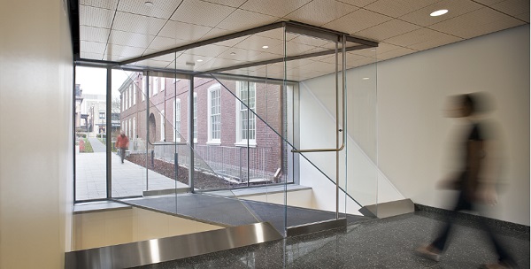
5.2.33-D
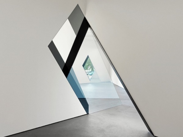
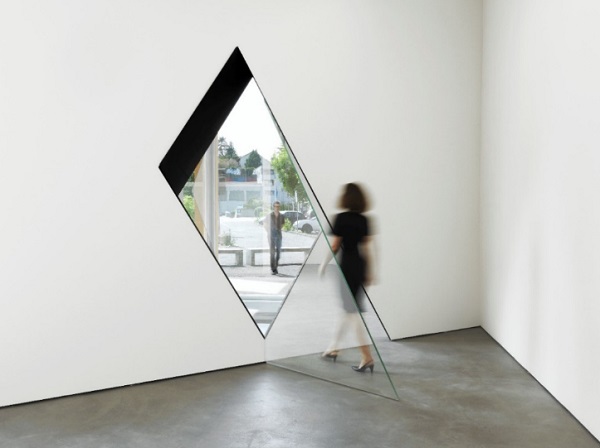
In Sarah Oppenheimer’s temporary installation at the Kunsthaus Baselland in Switzerland, entitled 33-D, glass also provides a platform on which images are reflected and redirected. The artist developed her work to integrate into the existing structure of the gallery, rather than to act as an autonomous object within it. In real-time, occupants see multiple people, in multiple spaces, on single planes of glass. In this way, the artist’s work adds fluidity to the existing architectural divisions.
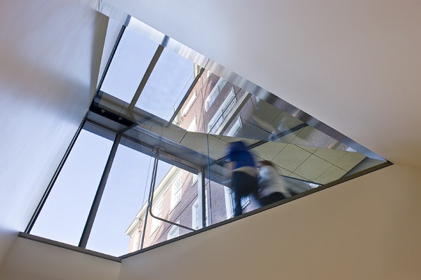
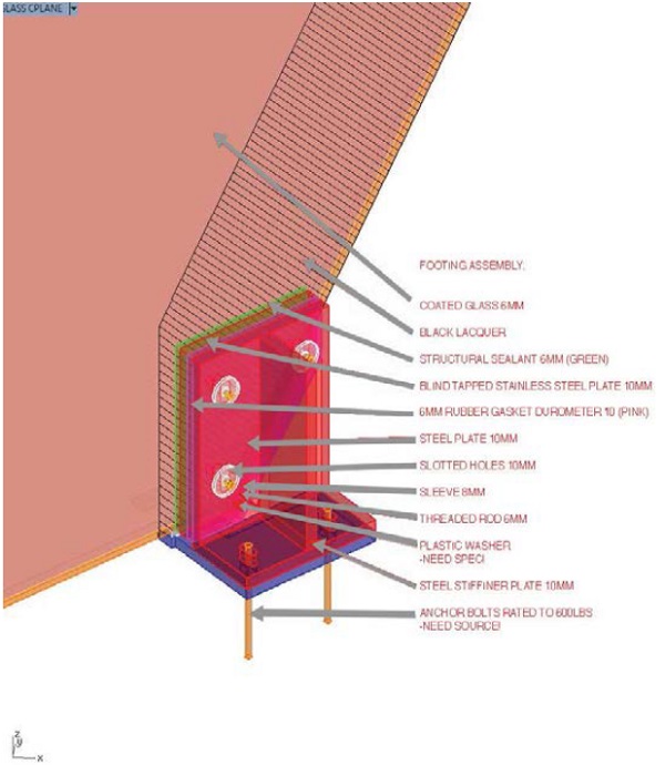
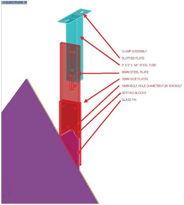
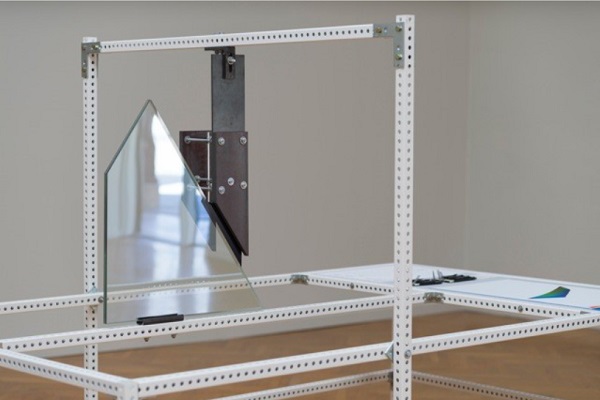
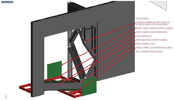
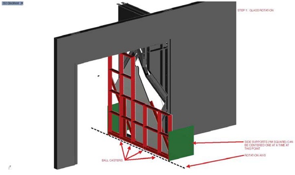
Two trapezoidal sheets of glass are mounted through openings in the gallery’s partition walls, linking adjacent rooms as part wall, part mirror, and part projection. The bottom edge of each angular glass lite floats just above the floor plane with only three minimal support points, each of which is concealed within the wall or at floor level. Fabrication limitations and a complex assembly sequence required the glass to be as light as possible, yet strong enough to withstand installation manipulation without breaking.
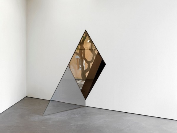
Because of the location and minimal size of the three supports for each lite of glass, torsional stiffness under incidental contact by art (and wine) enthusiasts was of prime concern, not only to maintain crisp and stable reflections on the glass, but also to minimize the chances of glass breakage under rotational deformation. In order to determine the incidental contact load for which to design the glass, we utilized the requirements for a guardrail infill panel from the IBC, which is a 0.22 kN concentrated force applied to an area of glass approximately 300 mm x 300 mm. We applied this force at the worst possible location on the glass, which is near the floor at the farthest point from the base support.Although the intent of the glass is not to function as a guardrail, the glass might act as such in certain circumstances, even within the art gallery setting where work is not intended to be touched. For this reason, and in accordance with the IBC code criteria for safety glazing, the glass was designed to be laminated.
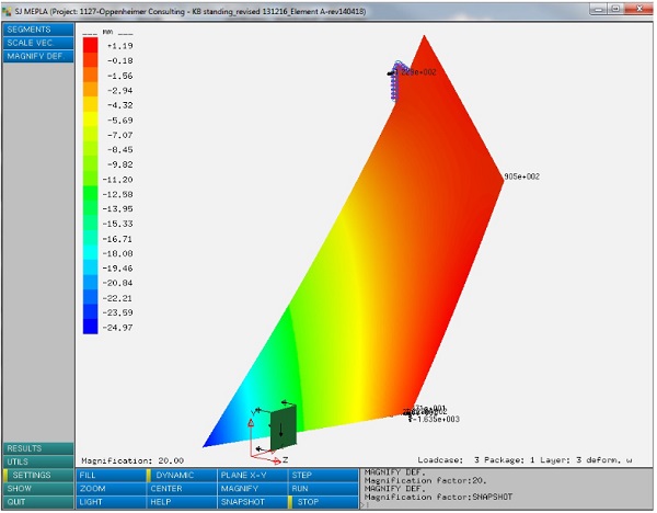
To study stress and deflection of the glass, we primarily utilized SJ Mepla. In preliminary models, the intent was to provide a single top and bottom support alone; however, the resulting high stress and deflection, coupled with the need to properly align the glass during installation, required the use of an additional intermediate support, concealed within the wall. Rather than increasing the overall thickness of the laminated glass, the desire was to keep the glass as light as possible to allow for ease of installation. The intermediate support helped reduced glass stress and deflection, allowing for a heat-strengthened (rather than fully tempered) laminated assembly.
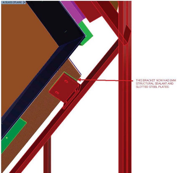
The single lower support for each glass lite not only carries the weight of the glass, but is also adhered to the face of the glass with one-part structural silicone to resist out-of-plane bending and torsional rotation. Gluing the support to a single face allowed the detail of the connection to remain hidden and contributes to the appearance of the glass floating just above floor level.
The upper support for each glass lite is completely hidden, composed of a rigid clamp around an extended tab of glass, designed to resist out-of-plane bending and torsional loads. The clamp assembly also allows for vertical movement of the glass due to anticipated deflection of the gallery floor below under live load.
The intermediate support is also hidden within the wall. This support is structurally glazed to one face of the glass, designed to resist lateral loads and help with glass alignment during installation.
Because each lite of trapezoidal glass would only be stable once in its final position, it was important to develop an installation method that would limit the possibility of glass breakage. Sarah Oppenheimer, whose team would personally install each lite of glass, developed a step-by-step sequence that both stabilized and protected the glass during installation.
6. Conclusion
These two case studies illustrate how the engineering of glass can fluctuate with design intent in unusual scenarios –when we cannot rely solely on conventional codes and standards to guide the analysis. In both cases, we see how knowledge of the properties of glass, combined with a practical understanding of the potential loads and risks applicable to each project, helped the artist successfully realize her unique and interactive installations. Through close collaboration, artist and engineer successfully integrated structural design, performance, and optics.
Acknowledgement
The author wishes to acknowledge Sarah Oppenheimer for her generous contributions in support of this paper.
References
- ASTM International: E1300-12a, Standard Practice for Determining Load Resistance of Glass in Buildings, West Conshohocken, PA (2012)
- International Code Council, Inc.: 2015 International Building Code, Country Club Hills, IL, USA (2015)
- O’Regan, C. (The Institution of Structural Engineers): Structural use of glass in buildings (Second edition), London, UK (2014)