Giampaolo Rosati, Maurizio Orlando, Lorenzo Ruggero Piscitelli
Introduction
Differently from traditional structural materials, the structural behaviour of laminated glasses exhibits some anomalies due to the difference in the stressstrain laws of their components: glass is a brittle material (E ~70000 MPa), while PVB and SGP are thermoplastic materials with a visco-elastic behaviour (G varies in the range 0.1 ÷ 1000 MPa) [1] [2] [3] [4].
The paper presents the results of an experimental campaign on LG beams, bent around the section strong axis, in order to evaluate their lateral-torsional buckling load. Main factors which infl uence the stability of laminated glass beams are [5]:
• geometrical imperfections during the production and the installation phases,
• viscoelastic behaviour of interlayer materials,
• variation of the interlayer stiffness at varying temperature and load duration,
• elastic-brittle behaviour of glass.
Reasonably one can assume that these factors do not contribute all together in the same way to buckling phenomena[6], moreover it can happen that some of these factors reduce the effects of the others (e.g. the installation process can reduce the effects of production imperfections or both of them can affect negatively the structural response in the same direction). Moreover the temperature has been monitored continuously during all the tests.
Experimental setup
The test machine is formed by three steel elements. The central element counteracts the vertical load applied with an hydraulic jack atmid-span of the specimens, while the two lateral elements house the end restraints of the specimens.
In the vertical direction each specimen has been simply supported at both ends, moreover it has been equipped with two torsional restraints (Figure 1). At the interface between each support and the specimen, polymer materials, like polyester and polyethylene, have been used. The plates forming the torsional restraints have been tightened just to put them in contact with the specimen surfaces, in order to allow for the rotation of the end sections in their own plane.
Figure 1 - Layout of the restraints
The hydraulic jack is fi xed to a steel portal, which lies in the plane normal to the beam axis. The load application point can translate normally to the beam axis, following the horizontal displacement of the beam upper edge. Moreover the presence of an articulation between the jack and the specimen upper edge allows the rotation of the section weak axis with respect to the load axis (Figure 2).The displacements were monitored in the section positioned 150 mm far from mid-span, as mid-span section was not accessible (Figure 3). The error is negligible for 3m long beams, like those used in the tests.
Figure 2 - Transversal view of the test machine (dot-dashed lines highlight the rotation between jack axis and section weak axis)
Figure 3 - Longitudinal and transversal section of the specimen in the test machine
Analytical model
To evaluate the fl exural-torsional critical buckling load the following literature formulas have been used:
where E and G are the elastic and shear modulus, a, b, d and l are defined in Fig. 4.
Figure 4 - a) Beam dimensions; b) Cross section with three glass panes
The first formula above assumes that the load is applied on the beam axis, while the second one allows to take into account a vertical distance a of the load from the beam axis. The expected value of the critical load is included between the values calculated using the two formulas above. These formulas have been used to estimate the critical load for both the monolithic case and the case of three uncoupled plies.
The glass tensile strength has not been measured. The value of the characteristic tensile strength of fl oat glass has been assumed equal to 45 MPa. On beams with the tin side on the outer surfaces it was also possible to measure stresses induced by the thermal tempering process using a GASP® Polarimeter [9]. Stresses induced by the thermal tempering process were measured in 15 different points equally distributed between the end sections and mid-span of beams. The estimated value of the characteristic tempering stress is equal to 97.61 MPa, so that the total characteristic tensile streng this about 142.61 MPa.
For all specimens, both the cracking load of the inner float glass and of the outer tempered glass plates were evaluated. The collapse load of the specimen is included between the collapse load obtained for the case of fully collaborating float glass (even if cracked, thanks to the action of the interlayers) and the case of two tempered glass plates with non-collaborating central float glass.
Experimental results
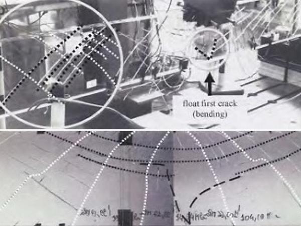
Tests were performed on four samples (300P1, 300P2-PVB- and 300S1, 300S2-SGP-). For beams assembled with PVB the collapse of the inner float glass happened with a first crack at a load included between 24kN and 32kN. The evolution pattern of the cracks howed a progressive and uninterrupted growth towards of the neutral axis of the beam (Figure 5).
Figure 5 - Evolution of first crack of sample 300P1 laminated with PVB (bending)
At a load of 66 kN the first specimen (300P1) exhibited a second crack with the same characteristics of the first one, while the second specimen (300P2) buckled at a load of 32.7 kN. Due to lateral displacements and stresses induced by the flexural-torsional buckling, the cracking pattern followed a different evolution (Figure 6). Cracks in the regions far from the load application point are due prevalently to shear and torsion. These cracks start from the centre of gravity of the section and develop slowly along the direction inclined by 45° towards both the lower and upper edges.
Figure 6 - Crack evolution of sample 300P2 laminated with PVB (torsion and shear)
In the mid-span section cracks were influenced by bending moment (Figure 7).
Figure 7 - Crack evolution at mid-span of sample 300P2 laminated with PVB (torsion and bending)
Figure 8 - Crack history in float glass plate of sample 300S1 laminated with SGP
The evolution of the crack pattern of the inner float plate in beams assembled with SGP is very different from those made with PVB. The number and density of cracks is higher than in samples laminated with PVB due to the higher capacity of SGP to transfer shear stresses. Up to 11 cracks were observed in sample 300S1 (Figure 8) and eight cracks in specimen 300S2 before the collapse of the tempered glass plates.
Experimental ultimate loads agree with the calculated theoretical values for both the float plate and the tempered ones.
Figure 9 - a) Vertical displacement at mid-span; b) Load history
Concluding remarks
The experimental campaign demonstrated how the instability phenomena depend upon a variety of parameters. Between the two beams laminated with PVB only the second beam exhibited a buckling phenomenon before collapse; the first beam exhibited a slight lateral displacement only at collapse, so that its failure cannot be related to a real buckling phenomenon.
The most evident difference between the two tests is the position of the first crack in the inner float plate: in the first beam cracks happened at one-third and two-thirds of span, so that at midspan the bending stiffness around the section weak axis was maintained. In the second beam the first (and only) bending crack appeared at mid-span, causing a significant reduction of the bending stiffness around the section weak axis.
The two SGP beams showed an overall greater bending stiffness even after the failure of both tempered glass plates. Moreover they exhibited a greater capacity than PVB beams to contain cracks of the float. Inner cracks due to bending did not extend too much towards the upper edge, so that over 40% of the inner plate section remained fully collaborating until the end of the test. This effect, together with a greater interlayer stiffness, helped to avoid the loss of stability.
Acknowledgments
The authors gratefully acknowledge funding from the Italian Ministry of Education, University and Research (MIUR) and Prof. Luigi Biolzi for useful hints.
References
[1] J. Wurm, Glass Structures: design and construction of self-supporting skin, Brikhäuser, 2007.
[2] S. Bennison, C. Smith, A. Van Duser and A. Jagota, Structural performance of laminated glass made with a “stiff” interlayer, Wilmington, 1988.
[3] J. Ferry, Viscoelastic properties of polymers, New York: Wiley, 1980.
[4] S. inc., Corporate Overview, 2009.
[5] A. Luible, Stabilität von tragelementen aus glas, École Polytechnique Fédérale de Lausanne: Thèse no. 3014, 2004.
[6] R. Kasper and G. Sedlacek, Structural use of glass beams, Institute of steel construction of the University of Aachen.
[7] S. Timoshenko and J. Gere, Theory of Elastic Stability, McGrow Hill, 1961.
[8] W. C. Young and R. G. Budynas, Roark’s Formulas for Stress and Strain, McGraw-Hill, 1989.
[9] “http://www.strainoptics.com,” Strainoptics, Inc. 108 W. Montgomery Ave. North Wales, PA 19454 USA. [Online].
Authors
Giampaolo Rosati
Politecnico di Milano
Maurizio Orlando, Lorenzo Ruggero Piscitelli
Università degli Studi di Firenze, Italy
Source: Rivista della Stazione Sperimentale del Vetro