
Authors: Micheal Drass & Michael A. Kraus
Source: Glass Structures & Engineering | https://doi.org/10.1007/s40940-020-00128-4
Abstract
This paper deals with the application of the semi-probabilistic design concept (level I, DIN EN 1990) to structural silicone adhesives in order to calibrate partial material safety factors for a stretch-based limit state equation. Based on the current legal situation for the application of structural sealants in façades, a new Eurocode-compliant design concept is introduced and compared to existing design codes (ETAG 002). This is followed by some background information on semi-probabilistic reliability modeling and the general framework of the Eurocode for the derivation of partial material safety factors at Level I. Within this paper, a specific partial material safety factor is derived for DOWSIL 993 silicone on the basis of experimental data.
The data were then further evaluated under a stretch-based limit state function to obtain a partial material safety factor for that specific limit state function. This safety factor is then extended to the application in finite element calculation programs in such a way that it is possible for the first time to perform mesh-independent static calculations of silicone adhesive joints. This procedure thus allows for great optimization of structural sealant design with potentially high economical as well as sustainability benefits. An example for the static verification of a bonded façade construction by means of finite element calculation shows (i) the application of EC 0 to silicone adhesives and (ii) the transfer of the EC 0 method to the finite element method with the result that mesh-independent ultimate loads can be determined.
Introduction and current situation
State-of-the-art glass façades are designed with a strong emphasis on a transparent appearance with minimal visibility of the supporting structures. During the last fifty years a lot of experience with structural silicone adhesive joints in façade design has been gained worldwide. Beginning with linear adhesive joints, which are used along a window system for homogeneous load transfer (Staudt et al. 2018), up to local fixings, where glass panes are only bonded locally with so-called point fixings (Drass et al. 2019b; Santarsiero and Louter 2019). More recent developments deal with so-called laminated joints, in which either a puck is laminated into a laminated safety glass (LSG) or something is laminated onto a glass (Bedon and Santarsiero 2018).
For the dimensioning of silicone adhesive joints in façades, there are two standards, ETAG 002 (2012) and ASTM C1401 (2002), which are common practice throughout the world. Both calculation methods are based on a linear analysis of the geometrical and material behavior and assume an even load distribution. Furthermore, a constant stress state of the adhesive is assumed, which leads to a nominal stress analysis. In order to ensure sufficient redundancy or safety in the design of the silicone adhesive joint, these two standards use a global safety concept, so that modeling inaccuracies (load and constitution behavior), temperature, humidity and aging effects (salt, detergent, SO2, UV) are covered.
Therefore, a global safety factor of γtot=6 is introduced to achieve a sufficiently large safety margin (ETAG 002 2012). Regretfully, the exact history of the determination of the global security factor γtot cannot be reconstructed at this time based on the current version of ETAG 002 (2012). Therefore, a discussion about the safety factor has been sparked in the industry today and the demand for a comprehensible calculation of a correct and justifiable safety factor has arisen.
Given that little work is currently being done on the methodologically correct and thus Eurocode-compliant derivation of a partial safety factor for silicone adhesives in the façade sector, this contribution deals on the one hand with the development and presentation of a Eurocode-compliant partial safety factor, the discussion of the influence of potential limit state functions and on the other hand with the implementation of a Level I approximation of a partial safety factor for the silicone adhesive DOWSIL 993.
The proposed methodology is generally valid, so that a partial safety factor can also be derived for other structural silicones under different limit state functions. The described method is based on the calibration procedure given in Eurocode EC 0 and additionally uses test results and modeling content from ETAG 002 (2012) to provide a simple link between the two concepts. With the help of the determined partial safety factor, the connection between the two concepts is easily established and it is possible to design and calculate silicone adhesive joints according to the partial safety factor concept of DIN EN 1990 Eurocode (2010).
The paper concludes with a practical example in which a bonded façade construction is dimensioned. As a highlight, the paper transfers the safety factor to the Finite Element Method (FEM) with the result that for the first time mesh-independent ultimate loads can be determined with the remark that one simple and easy FE calculation has to be performed on the H-sample to calibrate the structural parameter according to Eurocode.
Historical survey of design philosophies
Historically, there are two types of design philosophies with different safety concepts for the design of building components in civil engineering:
- allowable stress design method with a global safety concept,
- limit state design method with a semi-probabilistic safety concept.
In the following, both concepts are briefly presented for reasons of comprehensibility.
Allowable stress design method with global safety concept
Structural buildings have been designed in the past under the principle “the greater the uncertainty, the greater the factor of safety must be for this structure”. Accordingly, safety factors of magnitudes 1-6 were chosen depending on the structure, uncertainties in loads etc. However, on the one hand there was no normative regulation on how the safety factors should be calculated accordingly to a standard and on the other hand, reliability analysis provided guidance for obtaining theoretically and methodically correct safety factors for given levels of reliability but with no formal governmental accreditation. Therefore, these safety factors always were determined based on the experience of the respective engineers and designers.
The reduction by a safety factor was related to a characteristic strength value of the material under investigation, which was determined from experimental observations. The selection of the safety factor then depended on the target reliability of the strength estimation. In the second half of the nineteenth century, the theory of elasticity began to become accepted in the practice of structural engineers. This is also the reason why the design is carried out with linear calculations (both material and geometrical) based on engineering or nominal stresses, which is known as allowable stress design (ASD) method.
The ASD, using a global safety concept, calculates the maximum load or stress in the component for the entire life cycle. As a result, the limit state is reached on the action side using linear elasticity theory. For structural silicones, an engineering stress-based limit state function is commonly used. In the design, the calculated maximum stress must be smaller than the characteristic strength (5% quantile) of the examined material reduced by a global safety factor. If this process is summarized in terms of formula one obtains
In (1), the parameter σ represents the engineering stress in the material under maximum load for the whole lifetime of the structure, σdes is the (engineering) design strength, σlim the characteristic strength of the material and the abbreviation FS stands for factor of safety. Hence, the ASD approach is also applied in ETAG 002 (2012), which regulates the design of silicone adhesive joints.
Following the comments of Blockley (1992), the ASD method can be summarized in the traditional way as follows:
- Under service loads, all parts of the construction behave linearly elastic.
- In case the service loads have been calculated to be so high that the probability of exceeding them is low, and if the allowable stresses are chosen to be a sufficiently small fraction of a limit stress, then the structure has an excellent chance to have no damage within its lifetime.
This definition is also taken up by ETAG 002 (2012), which assumes linear elastic material behaviour for reasons of simplicity. The ASD approach is characterized by its simplicity and vividness, so that it quickly found its way into engineering practice and has established itself over several decades. It can also be said that this approach is conservative and therefore on the safe side. Finally, the ASD approach is a fully deterministic approach in accordance to Marek and Kvedaras (1998).
However, there are also many disadvantages for the above-mentioned concept from a scientific, probabilistic and economic point of view, which Blockley (1992) summarises as follows:
- Stress-strain relationship is not always linear, especially not for structural silicone adhesives.
- Material non-linearities may occur due to time effects (creep and relaxation) which are disregarded.
- Load effect and deformation are not always in a linear relationship.
- The material behavior beyond the linearity limits can be ductile with load carrying capacity reserves.
- The probability of exceeding the limit state at the beginning of non-linearity depends decisively on the statistical properties of the loads, the materials, the idealizations used to create a calculation model, etc. Consequently, the reliability of the elements within the structure or the reliability of the different structures can significantly fluctuate.
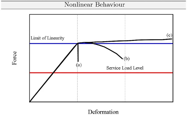
To illustrate this and to address nonlinearities of structures, joints or materials, Fig. 1 is an example of it.
Here, one can see that the load-deformation behaviour past the theoretical limit of linear response may be brittle, semi-ductile or ductile with very large reserve. In an ASD approach, however, the good-natured ductile behaviour cannot be taken into account. Therefore, the ASD approach in this example gives the same result for all three fracture behaviors, which can be classified as conservative.
Additionally, it is important to note at this point that many of the limitations mentioned are violated in their general validity by ETAG 002 (2012). If one takes a closer look at ETAG’s concept for the static dimensioning of silicone adhesive joints and generally the structural behavior of silicone adhesives, they behave non-linear-elastically (Drass et al. 2019a, b), are time- and rate-dependent (Kraus et al. 2017) and tend to creep under permanent load (Botz et al. 2019).
According to the list of disadvantages defined by Blockley (1992), new concepts for any type of material have been developed which circumvent the mentioned disadvantages. Here the so-called limit state design method has gained acceptance. It no longer concentrates only on the service condition under full load and reduction of material resistances, but deals with the limit of structural usefulness.
Limit state design method with semi-probabilistic safety concept
In the limit state design (LSD) method, the limit strength, ultimate strength, collapse strength, maximum capacity of structures, columns, beams or connections is calculated and then reduced to take into account possible influences from uncertainties in the strength of materials, manufacturing aspects and uncertainties of the structures in the final state after construction. The factorized strength, or resistance side, is then evaluated against the calculated load effect due to the corresponding maximum loads.
The loads, also called the action side, are then increased to take into account the uncertainties of the loads acting on the structure during its lifetime. In the evaluation of structural reliability, the concept of a limit state surface has thus become established. Here, the multidimensional domain of random variables is divided into safe and uncertain domains (Marek and Kvedaras 1998).
The safety and reliability of buildings is on the one hand determined by the variability within the actions and resistances of it and on the other hand by potential errors in planning, execution and use. Human misconduct however, cannot be detected, handled and covered by a safety concept, but must be excluded as far as possible by targeted measures such as checking of a structural design computation, quality assurance during the construction process of the structure and maintenance during use. Only the stochastic character of the input variables for actions and resistances can be determined by probabilistic methods. This requires a quantification of the stochastic uncertainties in actions and resistances.
Basically, the core of the design philosophy in DIN EN 1990 Eurocode (2010) is the solution of the inequality
![]()
with
![]()
and

In the above-mentioned equations, Ed represents the design value of an action and Rd the design value of the resistance, the indices d means design and k stands for its characteristic value. To calculate the limit state of the action side, the characteristic value Ek is multiplied by a factor γQ, whereas the resistance side or the characteristic value Rk is divided by a partial factor γM covering uncertainties in the resistance model.
Considering (2), both the action side and the resistance side are calculated separately as limit states and compared against each other. The partial safety factors for established materials such as concrete, steel or timber have been calibrated such, that a certain economically acceptable target reliability (given in and defined by the national annexes of the Eurocode 0) is reached. In contrast to ASD, material and geometric nonlineraties and imperfections as well are considered in the LSD approach which is a major advantage.
The LSD approach provides the same results or is identical to ASD for the case that the end of the elastic reaction is the limit state, the structure is perfect and the material behaviour is ideally linear elastic. To illustrate the different approaches once again, we will take a closer look at the action side in the following. In the case of LSD, the limit state of the action is calculated and it is checked whether the actual load is below it. With ASD, on the other hand, the strength limit must be maintained under the actual load. To illustrate the differences between both approaches, Fig. 2 can be adduced.
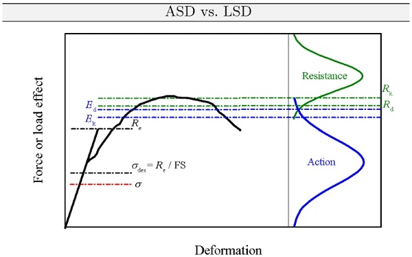
It is quite clear that ASD ignores the non-linearity and may lead to conservative results. An opposite effect can occur in insulating glass under climatic loads, where it can be on the unsafe side if the non-linearity of the shear bond, for example, is ignored.
The LSD approach can again be divided into two subgroups. The semi-probabilistic approach calculates partial safety factors on the impact and resistance side to define both limit states. From the designer’s point of view, this concept is still deterministic, but a probabilistic approach is found in the safety factors. Hence, this method is called the semi-probabilistic partial safety factor concept. The second approach deals with fully probabilistic methods for the implementation of reliability assessment of structures. This approach is not described in detail in the following and requires greater efforts in terms of modelling and evaluation of the problem at hand. For other materials such as steel or concrete, the semi-probabilistic approach is state of the art and has been introduced throughout Europe by the EC199x series and does not pose any difficulties for civil engineers (DIN EN 1990 Eurocode 2010), especially engineering education on universities since ten years teach Bachelor and Master students this design philosophy.
With regard to the construction industry, reliability is assessed by comparing the calculated reliability index β with the reliability index that is regarded as adequate for the system under evaluation from previous experience. For this purpose, one must establish a relationship between the capacity Rd (for example, the strength) of the system and the demand Ed (for example, the load) such that if capacity and demand are equal, there is a limiting state of interest. The margin of safety, defined as S=g(E,R)=R−E, is another example of this state, where S>0 represents the safe state, S<0 the failure state. For reasons of completeness, S=0 defines the limiting state. Accordingly, the probability of failure pf is given by
![]()
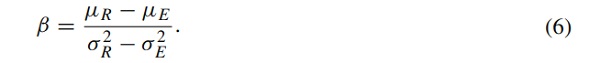
where the Pr[∙] defines any probability operator applied to the argument ∙. A fundamental measure of reliability theory is the so-called reliability index β, which is defined as a measure of an assigned probability of failure at a design point. The reliability index is usually set to β=3.8 for the ultimate limit state and the permanent design situation for a design life of a building of 50 years. The reliability index can be calculated by the expected value μ and the variance σ2 under assumption of a Gaussian distribution for the action and resistance side
The terms safety and reliability play a decisive role in the construction industry. For example, the safety concepts currently used in construction are based on a semi-probabilistic safety concept with partial safety factors on the action and resistance side. Since the action side is already described by the Eurocode, the aim of the present study is therefore to derive a partial material safety factor for a structural silicone according to the Eurocode, so that a uniform design procedure for bonded façade systems can be established. Figure 3 gives a general and schematic overview of the partial safety factor concept according to DIN EN 1990 Eurocode (2010). From this diagram, it is directly evident how the partial safety factor influences the resistance side.
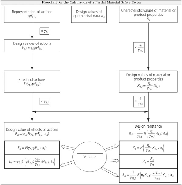
It is important to note that according to the Eurocode there is a partial safety factor γm for a material or product property and a partial safety factor γM for a component property, taking into account model uncertainties and size deviations.
Calibration of partial safety factor
In the last section two different design philosophies for the design of building structures were presented in general. In this section, the material resistance according to DIN EN 1990 Eurocode (2010) will be derived specifically for the structural silicone DOWSIL 993.
It shall be shown that on the one hand the derivation of a partial safety factor at a given limit state function according to DIN EN 1990 Eurocode (2010) is possible in a few lines of code. On the other hand, the LSD approach with the partial safety factor concept for structural silicones will be demonstrated for the first time. The advantages are that the non-linear material behavior of the silicone is taken into account, which leads to less conservative results. This allows a better utilization of the silicone, i.e. the design is more material-orientated. Furthermore, by using DIN EN 1990 Eurocode (2010), bonded glass components can be verified with one and the same safety concept without mixing the ASD and LSD approach. This offers advantages in the calculation of bonded façade components, since two different calculations (once ASD and once LSD) do not have to be performed.
Mathematical framework: partial material safety factor
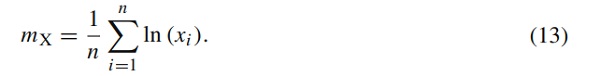
Following DIN EN 1990 Eurocode (2010); Sørensen (2002), the design values of material or product properties X are determined by
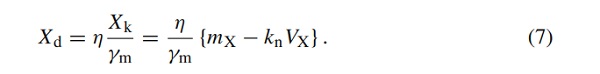
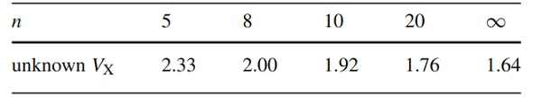
In this context, Xk represents the characteristic strength value (5 % quantile) and η is the mean value of a conversion factor that reflects differences between the material strength in the calculation model and in the actual structure as well as laboratory size effects (humidity, temperature, scale and size effects, etc.). Typically, η=1 can be assumed, cf. DIN EN 1990 Eurocode (2010). However, since in this paper more concern is put on the factor η, it is calculated or put in connection with the ETAG 002 (2012). Returning to (7), the variable mX describes the mean value of the material property X for n samples, kn represents the fractile value for the characteristic value and VX is the variation coefficient for the material property X.
Real design resistance, in contrast to the design values of material or product properties, also includes uncertainties in the resistance model, e.g. geometric deviations. In this case, the design resistance Rd is defined by
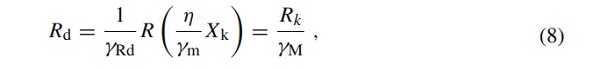
where γM is the partial safety factor covering the uncertainties in the resistance model (including the partial factor for the uncertainty in the material property described by γm, the uncertainty in the structural model of the structural members and the geometric data defined by γRd and η representing the mean value of the conversion factor that takes into account volume and scale effects, the effects of moisture and temperature, etc.).
Since the design resistance is defined according to DIN EN 1990 Eurocode (2010), the mathematical framework for determining the partial material safety factor is presented below. Following the simplified level I approach according to DIN EN 1990 Eurocode (2010), whereby at this point a suitable and meaningful mechanical model is assumed, then the partial safety factor γM is computed by

where αR represents a weighting factor for the resistance and β is the reliability index. The coefficient of variation VR is computed by:

where the components are defined as:
- VM: coefficient of variation for model uncertainty of structural silicone sealant
- VG: coefficient of variation for the geometry
- VF: coefficient of variation for the structural silicone sealant strength.
The coefficient of variation for the structural silicone sealant strength can be calculated from experimental data by

where the standard deviation sX is given by
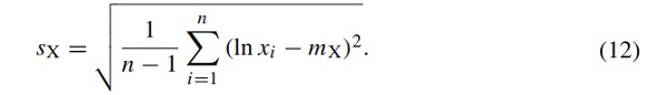
The standard deviation sX depends on the mean value mX of the strength, which is computed via
Based on this and applying a log-normal distribution for the material property X, which is strongly recommended by Fischer (2001) for small sample sizes with a certain coefficient of variation, (7) can be reformulated by
![]()
which can be used to calculate the characteristic failure strength of the analyses material, e.g. a DOWSIL 993 structural silicone. The quantile factor kn is provided in Tab. 1.
Table 1 Values of knkn for estimation of characteristic values (5 % fractiles), (DIN EN 1990 Eurocode 2010) - Full size table
Note that the partial safety factor alone is not sufficient for the design, but that the strength parameter is also required for the design limit state analysis. Both will depend in value on the applied limit state function and statistical modeling, which will be shown later in this paper. In general, with increasing modeling and testing efforts, both the partial safety factor and the characteristic strength value can be estimated with a small uncertainty and thus smaller safety factors.
Partial material safety factor for DOWSIL 993 using a stretch-based limit state function
In contrast to publications on the calibration of partial safety factors for stress based limit state functions, cf. Drass and Kraus (2020), Kraus and Drass (2020), the present work calibrates the partial safety factor for DOWSIL 993 based on experimental data from Staudt et al. (2018), Staudt (2017), Rosendahl et al. (2019) using an adaptive stretch-based failure criterion.
Returning to the computation of the partial safety factor γM for the structural silicone adhesive DOWSIL 993 considering a stretch-based failure criterion (i.e. limit state), the proposed formula apparatus is combined with constraints from ETAG 002 (2012) to calculate γM using the Level I method of DIN EN 1990 Eurocode (2010). Starting with the determination of the coefficients of variation for the stretch-based limit state function, the coefficient for model uncertainties will be derived in the following.
Model uncertainties for the stretch-based limit state function: coefficient of variation
The derivation of the model uncertainties for the partial safety factor γM for the structural silicone DOWSIL 993 is calibrated using measurement data of different stretch failure modes based on the investigations of Staudt et al. (2018), Staudt (2017) and Rosendahl et al. (2019).
To describe the multiaxial failure of the silicone adhesive, uniaxial tension and compression tests and so-called circular shear tests were performed by Staudt (2017). The details of the tests are described in Staudt (2017) and in Rosendahl et al. (2019) the experimentally determined failure points in the three-dimensional stretch space of all individual tests were summarized.
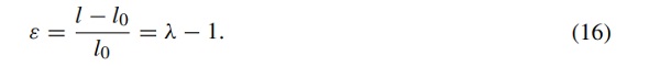
In the one-dimensional case, the stretch λ is a measure of the elongation or normal strain of a differential line element. It is defined as the ratio between the final length l and the initial length l0 of the material line element:

The relationship between the engineering or nominal strain and the stretch is given by
For the sake of clarity, a derivation of the stretch in three-dimensional space is not shown here, but only referred to in Appendix A.
In order to describe the model inaccuracies with regard to the failure description of DOWSIL 993 under arbitrary deformation, the three-dimensional failure stretches tabulated in Rosendahl et al. (2019) are transferred to a two-dimensional space, the so-called π plane. Again, the exact derivation of the π plane is omitted and reference is made to Appendix B. The representation of the failure points in the π plane is shown in Fig. 4a.
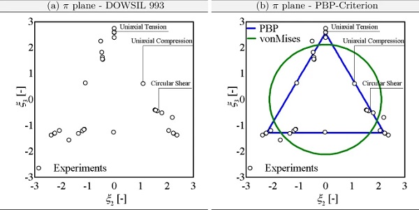
The aim is to approximate the failure stretches of the analysed structural silicone using a suitable failure criterion. A very adaptable and comprehensible criterion for isochoric distortional failure was proposed by Podgórski (1984) and developed in a similar manner by Bigoni and Piccolroaz (2004). In the following this criterion is abbreviated as PBP criterion. Using the notation of Rosendahl et al. (2018), the distortional failure criterion Φiso is described in stretch space by
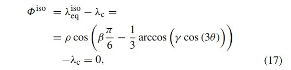
where ρ represents the distance from the hydrostatic axis to the boundary of the failure surface in the deviatoric plane and θ is the so-called Lode angle (see Appendix A). Both are functions of the deformation state. The parameters β and γ determine the shape of the failure surface and must be determined based on experiments. The threshold λc describes the size of the failure surface. In order to guarantee a convex failure surface, the shape parameters are restricted to the intervals β∈[0,2] and γ∈[0,1].
Approximating the failure stretches of DOWSIL 993 with the PBP criterion results in the following two-dimensional failure surface, which is also shown in the π plane in Fig. 4b. For the sake of completeness, the approximation by the von Mises-like criterion
![]()
is also shown, where I′2 corresponds to the second invariant of the deviatoric part of the Hencky strain tensor.
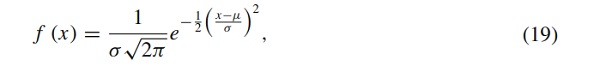
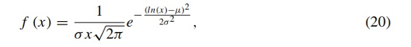
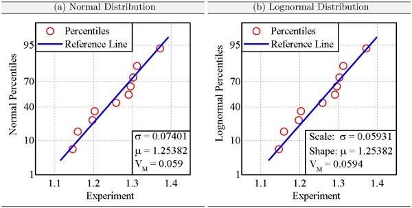
As can be easily seen, the failure points for three different deformation states, namely uniaxial tension and compression and shear, are very well approximated with the PBP criterion. In contrast, the von Mises-like criterion is not at all suitable to describe the failure states, which must lead to a very high model uncertainty. On this basis, the model uncertainty is calculated according to the explanations of Gulvanessian et al. (2012b). In relation to the PBP criterion, an equivalent stretch of λc=1.2538 was fitted, whereas that of Mises provides λc=2.5691. If the model uncertainty for the PBP criterion is evaluated under the assumption of a normal distribution, a variation coefficient of VM=0.059 results. Assuming a lognormal distribution, which is especially useful for small amounts of data, a VM=0.0594 results. As a reminder, the normal distribution is defined as
where σ represents the standard deviation and μμ gives us the mean value. In contrast, the lognormal distribution function is defined by
where σ defines the scale parameter and μ is the shape parameter.
Accordingly, both distribution functions deliver an almost identical value, which is later used to calculate the partial material safety factor.
Geometry uncertainties: coefficient of variation
Furthermore, the geometric deviations of the adhesive joint must be taken into account to evaluate the partial safety factor for DOWSIL 993. Since there is no exact knowledge of the geometry from the underlying data set, as it was simply not measured exactly, an assumption must be made for the geometry uncertainty. Here, a value of VG=0.10 is assumed. This guideline value is based on personal communications and experiences of the Seele company. Since the value of the geometric uncertainty is only an assumption, it can be adjusted individually and reduced by factory production controls in the form of measurements and consecutive statistical analysis. In summary, however, this value lies within a trustworthy range based on experience with industrial applications of DOWSIL 993 (Fig. 5).
Determination of partial safety factor γM for a stretch-based limit state function
In terms of (9), the weighting factor for the resistance according to the Level I method is assumed to be αR=0.8. According to DIN EN 1990 Eurocode (2010) this factor is on the safe side. Generally, the reliability index is considered with β=3.8 for the ultimate limit state, which corresponds to a permanent design situation with a target lifetime of the building of 50 years.
So far, the conversion factor η according to (9) has not been considered in the computations of the partial material safety factor for the stretch-based limit state function. To account for further model uncertainties and conversion aspects, the conversion factor η is now linked to requirements from ETAG 002 (2012) to have a reasonable assumption regarding the model uncertainty under consideration of ageing effects.
Typically, ageing phenomena occur in façades due to water, temperature, UV, NaCl, SO2, detergent exposure. These adverse ageing effects are experimentally tested according to ETAG 002 (2012), where the ratio of the aged nominal strength (in terms of engineering stress) to the unaged strength must be greater than 75 %. Figure 6a shows the barrier in accordance to ETAG 002 (2012) for tensile loading of an ETAG H-probe as a grey box according to the experimental engineering stress data available. In addition to the box plot of the strengths (engineering stresses), the log-normal distribution of the unaged and artificially aged tests is shown in Fig. 6b. It is interesting to see that the slopes change at different temperatures. Accordingly, the temperature has a great influence on the distribution of the engineering stress strengths. If one looks at the artificially aged samples with NaCl and SO2, the gradient and thus the distribution of the strengths changes only slightly.
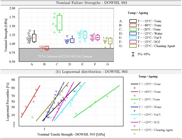
All averages of the nominal strengths of the artificially aged specimens are above the 75 % criterion, thus meeting the requirements of ETAG 002 (2012). This criterion therefore provides a lower limit value which must be met experimentally in order to be able to construct an SSG façade. Assuming this lower limit value is a true barrier according to ETAG 002 (2012), which includes all harmful influences such as temperature, water and UV storage as well as salt exposure, the conversion factor ηη can be determined accordingly:
![]()
This is a reasonable approach, creates a lower boundary for η and links ETAG 002 concept with DIN EN 1990 Eurocode (2010). It is to note that the conversion factor η can be adjusted according to the results of the ageing tests, if test results are available.
If one takes all previous assumptions as a basis and assuming that the uncertainties in the structural model of structural members is γRd=1, then the partial safety factor γM for DOWSIL 993 with a stretch-based limit state function reads
![]()
This value for the partial safety factors assumes 10 % for the coefficient of variation of the geometry and VM=0.0593 for the model VM. If the conversion factor is taken into account, η=0.75 must also be assumed. It is important to note that this partial safety factor is further adjustable by reducing the coefficient of variation of the adhesive joint geometry as a result of accurate factory monitoring and machine application of the adhesive joint.
A very important point at this stage is the assumption that for the uncertainties of the structural model of structural members the value is set to 1. This factor will be adapted for simulation by FEM, as will be shown later, in order to avoid the problem of stress singularities and thus make the FE solution independent of the mesh. The γRd factor will be determined by one simulation of an ETAG H-sample and then used for the calculation of the design resistance. The individual adaptation of γRd makes it possible to evaluate structural components independent of the mesh.
Discussion of the determined partial safety factor for structural silicone
Having obtained numerical value for the partial material safety factor with associated characteristic values for the DOWSIL 993, this section discusses the underlying assumptions in more detail.
In order to create direct comparability between the partial safety factor according to EC0 and the global safety factor γtot according to ETAG 002 (2012), it is assumed when converting γM into a global safety factor that only live loads affect the component. As a result, γM is multiplied by the partial safety factor on the action side of 1.5, resulting in a conservative global safety factor of
![]()
Comparing this with the global safety factor according to ETAG 002 (2012), a large reduction results despite consideration of damaging influences. The principal assumptions for the application of the proposed concept or the determined partial safety factor, however, is the application of suitable material models and failure criteria for the structural silicone under investigation in order to have the lowest possible uncertainty on the material side. However, the following points allow for more detailed and precise computation of the partial material safety factor in future research:
- ’realistic’ ageing protocols (deduction of load combination factors),
- fatigue,
- viscoelasticity,
- different performance / limit state functions g(E, R),
- multiple failure modes (distortional and/or dilatation) of the sealant,
- failure modes of the sealing application and the sealed system (series and/or parallel system behavior).
Validation example
The aim of this section is to show how to apply the semi-probabilistic safety concept for the static proof of silicone-adhesive connections using the FEM. This example deals in particular with a bonded façade element where the maximum load-bearing capacity under wind load is going to be calculated. Using the semi-probabilistic safety concept, the aim is to increase the applied wind suction load until the load-bearing capacity of the structural silicone adhesive is reached. A special feature of this section is that the verification of the adhesive joint is to be carried out via FE simulations. This results in the peculiarity that in the simulation with finite elements stress singularities at bi-material notches occur, whereby a mesh-dependent solution is obtained. This must be taken into account or circumvented in the design approach which will be shown later.
Since the partial safety factor on the basis of (22) has been calculated without considering uncertainties in the structural model of the structural members by γRd, which in the following is equated with stress singularities at bi-material notches, the parameter γRd must be additionally calibrated to obtain a mesh-independent solution for the determination of the ultimate load. To illustrate how this works, the verification concept and the necessary steps are briefly introduced below and then explained in detail using the example described above.
Methodology
The verification concept wil be divided into four steps, which are briefly described in the following:
- Step 1::
-
PBP criterion for 5% Quantile Values
- calculate 5% quantile values for uniaxial tension / compression and shear tests
- fit PBP criterion on 5% quantile values of experiments
- determine an equivalent stretch based on the 5% quantile Values →λc,5%
- Step 2::
-
Definition FE-Mesh
- definition of the FE mesh for the global model of the façade element, i.e. the mesh density of the silicone adhesive must be specified.
- definition of the FE-mesh for the ETAG H-Probe
- note: both FE-meshes must be identical!
- Step 3::
-
Calculation of γRd
- calculation ETAG H-sample in tension with Fk,5% and predefined mesh from Step 2
- evaluation of the principal stretches in the FE-model
- fit PBP criterion →λc,Rd
- calculation of γRd=λc,5%/λc,Rd
- Step 4::
-
Calculation of the design value λc,d
In the following steps 1-4 are presented in detail using the example of the bonded façade element located in Berlin, Germany. Details on the project will be provided, when the numerical model will be explained more in detail.
Step 1: PBP criterion for 5% quantile values
As one can see in Fig. 4a, the individual experiments, here uniaxial tension/compression and shear, are scattering, so that one must determine the 5% quantile value for each experiment individually on this basis. Hence, to calculate the 5% quantile values for the stretches in accordance to ETAG 002 (2012), the following equation can be utilized:
![]()
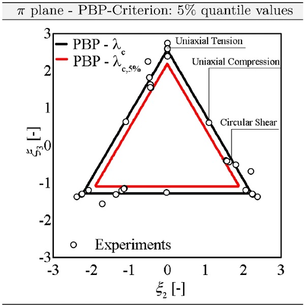
By calculating the 5% quantile values, the adaptive PBP failure criterion must be fitted to these data in order to calculate an equivalent stretch λc,5%. By doing this you get the equivalent stretch λc,5%=1.09592. For the representation of the π plane this means that the failure domain becomes slightly smaller (see Fig. 7).
Step 2: definition FE-mesh
In this section, a discretization for the global model of the façade element must be specified, which can also be transferred to the ETAG H-shaped test sample. Since we emphasize in this paper that we are able to calculate failure loads or carrying loads respectively independent of the mesh, we will examine three mesh variants in the following:
- 4×4×4 mm,
- 3×3×3 mm,
- 2×2×2 mm.
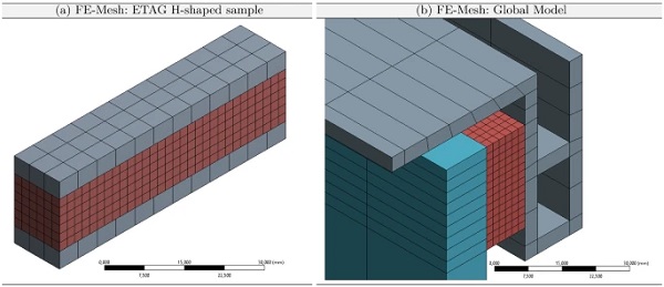
As can be seen from the list, the silicone is modeled with brick elements with exactly the same edge lengths. All following calculations are therefore carried out with these three different discretizations. As an example of the mesh variant 2×2×2 mm, Fig. 8 shows the ETAG H-shaped sample and a section of the façade element with the same mesh. The contact formulation in these examples was realized with so called Multi-Point-Constrained contact elements, so that due to this constraint non coincident nodes must be used in the mesh. However, it is essential that the contact formulation of the H-sample is identical to the formulation in the global model.
Step 3: calculation of γRd
In the third step the uncertainty in the structural model of structural members γRd will be determined. The authors are of the opinion that this safety factor should be calibrated using the stress singularities occurring in FE calculations as input. In the context of FEM, stress singularities are understood as the solution depends on the mesh density in the area of bi-material notches. These notches always occur in the region of the sticking of the elements of the silicone with glass or the substructure.
As a result, the stresses, strains and stretches always increase with finer mesh at the same load level. However, this effect must be avoided when dimensioning silicone adhesive joints, as otherwise the solution depends on the mesh, which means that it is very lightly to incorrectly dimension the joint. It is therefore of decisive importance to develop a method which, for example in the load bearing capacity calculation, always leads to the same results without being dependent on the mesh density.
Therefore, to be independent of the mesh density, γRd must be calibrated by one single numerical calculation of an ETAG H-sample under tensile load. The advantages are obvious. On the one hand, this safety factor can be determined by one simple numerical calculation, and on the other hand, complex mathematical methods such as finite fracture mechanics and expensive fracture mechanics tests can be omitted. In order to give the reader a clear understanding of this procedure, all necessary steps for determining γRd are presented in detail below.
As a first step, the geometry of the ETAG H-specimen or similar geometry must be entered into an FE program and meshed with the same mesh as that of the global model. This sample must then be pulled to the 5% quantile value of the tensile strength or tensile force. For the geometry of the H-shaped specimen of 12×12×60 mm selected here, the tensile force to be applied reads
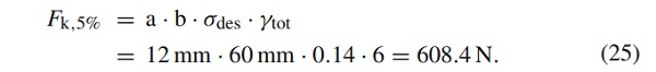
In this context, the pulled surface of the specimen (a⋅b) is multiplied by the design strength σdes of DOWSIL 993 and the global safety factor of γtot=6 to determine the 5% quantile value of the tensile force Fk,5%. This determined force is applied to the H-shaped numerical examples with three different mesh densities and then the governing stretches in the corners are evaluated. The mesh-dependent stretches are then in turn fitted by the PBP criterion again, so that three different equivalent stretches λc,Rd are obtained for the three different FE meshes. A summary is presented in Table 2.
Table 2 Simulation results for modified ETAG H-probe under tensile load for three different mesh densities and evaluation of the equivalent stretch according to PBP-criterion - Full size table
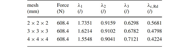
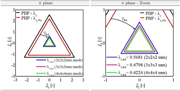
The PBP-criterion is then fitted with the mesh-dependent failure stretches determined from finite element simulations. This results in corresponding equivalent stretches λc,Rd, which are also summarized in Table 2 and are additionally shown in the π plane plot in Fig. 9. What can be clearly seen is, on the one hand, that with increasingly finer mesh the failure surface becomes larger and, on the other hand, that the failure surfaces calibrated on the FE calculations are significantly smaller than the 5% quantile failure surface determined on the experimental tests on DOWSIL 993.
To calculate the uncertainty in the structural model of the structural members, the following equation can be adduced:
The following table (see Table 3) summarizes this operation for the three different meshes:
Calculation of the design value λc,d
In the last step, the determined partial safety factor from (22) and the partial safety factor for uncertainty in the structural model of the structural members γRd must be harmonized with the PBP-criterion, so that FE-calculations can be carried out and carrying loads determined without being dependent on the mesh.
This is done simply by dividing the equivalent stretch λc,5% by both partial safety factors, so that the following applies
Since we examined three different mesh densities, the results are summarized in the following table (see Table 4).
Table 3 Evaluation of the uncertainty in the structural model of the structural members γRd for three different mesh densities - Full size table
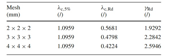
Table 4 Evaluation of the equivalent stretches λc,d for three different mesh densities - Full size table
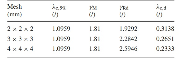
It should be noted that with Table 4 and more precisely the value for λc,dλc,d the dimensioning of the silicone adhesive joint can be carried out with the corresponding mesh density. If one decides on a mesh density of 2×2×2 mm for the structural silicone in the global model of the façade element, the value λc,d=0.3138 must be entered for the evaluation of the PBP criterion within the FE calculation.
If this procedure is followed, the silicone verification is carried out for the first time using the semi-probabilistic safety concept accordingly to EN 1990 Eurocode (2002) and it is also possible to determine carrying loads that are independent of the mesh density. A last important point is that with the tabulated values for λc,d any adhesively bonded facade structures can be calculated with the corresponding mesh density, as long as the corresponding tabulated value from Table 4 is used. Therefore, this is the first mesh-independent approach to design bonded structures using FEM.

Example: bonded façade element
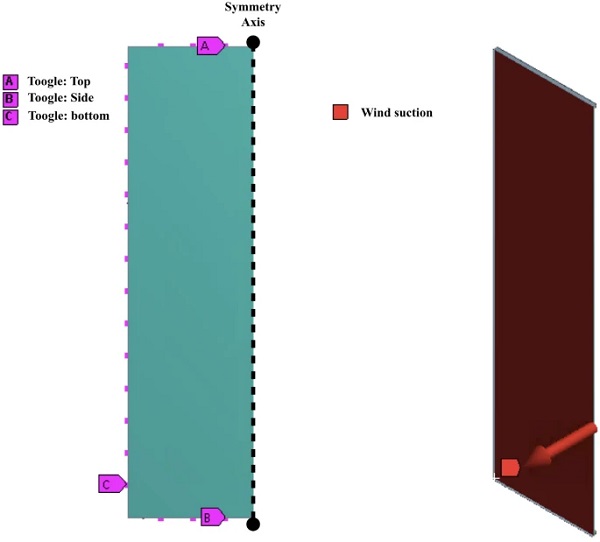
In this example, a bonded façade element has to be verified statically according to EN 1990 Eurocode (2002), i.e. the semi-probabilistic safety concept. In particular, this section deals with the numerical simulation of a bonded façade element with the dimensions 2700×5100 mm in order to make the static proof of the structural silicone adhesive. The product DOWSIL 993 is fictionally used as adhesive in the present example, which has the following joint dimensions (28×12 mm). A rendering of the bonded facade of the Voltair project in Berlin is shown in Fig. 10.
In this example, the present concept from Sect. 3 is used to determine the maximum load due to wind suction. Figure 11 shows the geometric model of the bonded façade construction exploiting symmetry.
The model consists of a laminated safety glass (LSG) 2 x 10 mm annealed glass with PVB layer in between. For reasons of simplicity, the LSG is represented with a surrogate model, i.e. a mono-pane. This mono-pane is then structurally bonded to the aluminum profile with the silicone adhesive DOWSIL 993. The bearing of the profile is done point-wise by so called toogle systems, so that the profile is kept at a distance of 300 mm. The external load is a wind suction load, which is increased until the maximum load-bearing capacity for the silicone adhesive is reached.
ETAG 002: analytical approach
Starting with the analytical calculation of the problem, ETAG 002 provides a hand calculation formula to obtain the maximum design wind load in accordance to the ASD approach utilizing a global safety concept, which is computed via

The advantages of the mentioned approach are the simplicity and quick application, but the disadvantages are the assumption of linear elastic material and structural behavior, the application of engineering stresses as design basis, the separation of tensile and shear stresses due to different actions, the high safety level, the very strong simplification of the load transfer, the neglect of uncertainties on the action side and the separate verification of bonded facade elements, since different safety concepts are used for glass and silicone. Due to the numerous disadvantages, it is essential to offer modern dimensioning approaches that circumvent the above mentioned disadvantages and still allow a safe design of the adhesive joint and the structure.
In addition, FEM verification is often required in projects, as the simplifications according to ETAG are too blatant and building owners and engineers are uncertain about its application. Therefore, the authors are of the opinion that for modern, bonded facades, the ETAG approach can be used for the basic evaluation and a preliminary calculation of the ultimate load, but that a more precise verification by means of FEM is decisive, since due to increasingly complex building structures and bonded joint geometries, the verification of the bond is certainly more complex than is covered by ETAG.
Finite element analyses
In this section, the results of the FE calculations are briefly presented. As the model is non-linear, the calculations are performed under large deformations. In order to obtain a good convergence, the wind suction load is successively increased until the PBP criterion in the silicone is exceeded. It is important to note that three individual calculations of the façade element were carried out, each with a different mesh density of the silicone. The mesh density was previously selected according to Sect. 4.1.2. The PBP criterion is also adjusted during its evaluation according to the implemented mesh density, so that for λc,dλc,d the values according to Table 4 must be used.
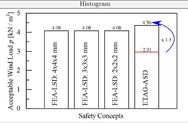
Figure 12 gives a histogram showing the numerically determined load capacities for different mesh densities. It can clearly be seen that the maximum wind suction load that can be absorbed according to EN 1990 Eurocode (2002) design reads pd=4.08kN/m2. It should also be noted that with the proposed concept from Sect. 4.1, the same loads could be determined for three different mesh densities. This means that the solution with the method proposed is independent of the meshing. This is a very important result because the concept is easily accessible, can be calibrated by engineers and complex methods such as finite fracture mechanics are not required. As can be seen additionally from the histogram, the wind suction load that can be absorbed based on ETAG’s approach is
![]()
using (28).
Here, it must be noted that wind loads that can be absorbed accordingly to EN 1990 Eurocode (2002) are so-called design loads, i.e. according to EN 1990 Eurocode (2002) a factor of 1.5 is still included on the action side.
In order to compare the wind load determined according to ETAG 002 (2012) with the wind loads mentioned above, the value according to ETAG may be modified as follows:
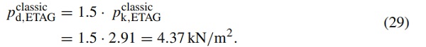
The comparison between (29) with the ultimate loads based on the FEM and semi-probabilistic safety concept is actually not quite correct, since, according to ETAG’s calculation method, one has already found its limit state function, i.e. no more wind load may be applied to the bonded facade. Nevertheless, we compare the value of ETAG with the value according to Eurocode by the fictitious increase of the calculated wind suction load from (28) with the factor of γQ=1.5. However, a very interesting result is that both approaches calculate almost identical maximum loads. However, since according to ETAG a slightly higher wind load was determined, this approach is on the unsafe side according to the considerations from the Eurocode.
Discussion and conclusions
This paper deals with the presentation and calculation of a partial safety factor for the structural silicone DOWSIL 993. A semi-probabilistic approach according to EN 1990 Eurocode (2002) was proposed and applied to determine a suitable partial safety factor. To illustrate the procedure, the methodological outline concludes with an exemplary probabilistic evaluation of a specific limit state for the structural silicone adhesive DOWSIL 993. The methodology is state of the art, but was applied for the first time to structural silicone adhesives with the application area of the façade. Furthermore, the concept according to the EN 1990 Eurocode (2002) was extended to the finite element method in such a way that a design is now possible without obtaining mesh-dependent results.
The value determined within the scope of this work shows that the partial material safety factor (also taking into account temperature and ageing and laboratory effects) is γM=1.81 and thus a global partial safety factor of γ∗tot=2.72 is justified, in the case of precise material modeling and failure description via the PBP criterion. Furthermore, the semi-probabilistic concept was extended to the finite element method in such a way that it is now possible for the first time to carry out Eurocode-compliant and even mesh-independent dimensioning of silicone adhesives in the façade sector.
In conclusion, however, it should be clearly stated that the concept presented and its application are subject to the following conditions:
- Application of a hyperelastic material model that can exactly represent any deformation state, e.g. Drass et al. (2018), Drass et al. (2019a) .
- The use of the stretch-based PBP failure criterion is mandatory.
- For now, only applicable to isochore failure.
- All given values are only applicable for the product DOWSIL 993.
Acknowledgements
Open Access funding provided by Projekt DEAL. The authors would like to thank the people and companies that contributed to this publication by making data, projects and measurements available. Special thanks go to the building owner VOLT GmbH & Co. KG, Uhlandstraße 181-183, 10623 Berlin as well as the company Knippers Helbig, Florian Scheible and Thiemo Fildhuth for providing us the rendering and project details the Voltair bulding in Berlin, Germany. Furthermore the authors would like to thank Schütz Goldschmidt Schneider Ingenieurdienstleistungen im Bauwesen GmbH and especially Sebastian Schula to be involved in the Voltair project.
Author information
Affiliations
M&M Network-Ing UG (haftungsbeschränkt), Lennebergstraße 40, 55124, Mainz, Germany
Micheal Drass & Michael A. Kraus
Institute for Structural Mechanics and Design, Technische Universität Darmstadt TU Darmstadt, Franziska-Braun-Str. 3, 64287, Darmstadt, Germany
Micheal Drass
Civil and Environmental Engineering, Stanford University, Y2E2, 473 Via Ortega, Stanford, CA, 94305, USA
Michael A. Kraus