Authors: Martin Larcher, Michel Arrigoni, Chiara Bedon, J. C. A. M. van Doormaal, Christof Haberacker, Götz Hüsken, Oliver Millon, Arja Saarenheimo, George Solomos, Laurent Thamie, Georgios Valsamos, Andy Williams and Alexander Stolz
"Design of Blast-Loaded Glazing Windows and Facades: A Review of Essential Requirements towards Standardization", Advances in Civil Engineering, vol. 2016, Article ID 2604232, 14 pages, 2016. https://doi.org/10.1155/2016/2604232
Abstract
The determination of the blast protection level of laminated glass windows and facades is of crucial importance, and it is normally done by using experimental investigations. In recent years numerical methods have become much more powerful also with respect to this kind of application. This paper attempts to give a first idea of a possible standardization concerning such numerical simulations. Attention is drawn to the representation of the blast loading and to the proper description of the behaviour of the material of the mentioned products, to the geometrical meshing, and to the modelling of the connections of the glass components to the main structure. The need to validate the numerical models against reliable experimental data, some of which are indicated, is underlined.
1. Introduction
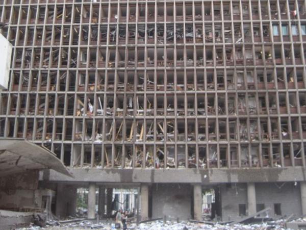
The recent terrorist attacks have shown that explosions could result in a massive failure of windows as seen in the terrorist attack in Oslo in 2011 (Figure 1). Glass is used in modern architecture widely as a part of facades often in combination with a steel substructure. However, glass is in general also the most fragile part of a structure and its failure results in splinters that could seriously injure persons inside the building. The windows of critical buildings and in general of critical infrastructure can be strengthened (and their protection increased), for example, by using laminated glass. This kind of intervention and the resulting enhanced protection can be identified in Figure 1, where some windows in the 5th floor have not failed.
![Figure 1 Terrorist attack in Oslo in 2011, failure of windows (from [5]).](/sites/default/files/inline-images/Fig1_220.jpg)
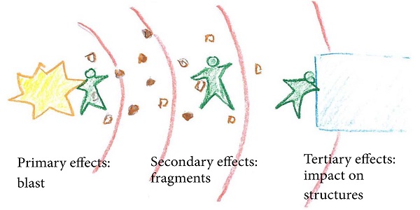
The particular vulnerability of glass is shown in the investigation of the Oklahoma City attack by Norville et al. [1]. In this study, a very large risk zone has been identified, where windows fail and their splinters could potentially injure people. Concerning explosion-induced injuries, the risk due to the primary blast effects on humans (Figure 2) is already described quite well by several authors [2]. However, this is not yet the case for secondary blast effects, which are due to the fragments propelled with high velocities and strike the human body. A relevant example of large scale explosion in a dense urban environment is the explosion of the AZF factory in Toulouse, France, in 2001, where more than 3000 people were injured, mainly by splinters [3]. This is an area of interest and of intense research. A straightforward procedure for assessing the additional risk due to the splinters as part of the secondary blast effects is currently under development [4].
(1) Numerical Simulations on Blast-Loaded Glass Systems. Several numerical investigations with various models concerning laminated glass have been conducted. Müller and Wagner [6] have shown that a layered shell element can represent the failure behaviour of laminated glass quite well. Simplified models are given by Timmel et al. [7] and Sun et al. [8] that apparently do not represent all failure mechanisms of laminated glass.
Some authors (Zhang and Hao [9], Bennison et al. [10], and Hidallana-Gamage et al. [11]) have presented 3D models with solid elements which allow use of a detailed material law for the interlayer. The number of degrees of freedom in this modelling increases rapidly. Examples and calculations with failure criteria of conventional glass are shown, for example, by Müller and Wagner [6] and Burmeister [12].
Several additional effects concerning laminated glass windows have also been investigated numerically. According to Zhang and Hao [9], the influence of the boundary conditions is very big. Therefore, a detailed modelling of the connection between the glass and the rigid structure, to which the window or facade is connected, is essential. The possible delamination of the laminated glass is investigated by Pelfrene et al. [13] using a combined shell-solid model. It is found that, depending on the polyvinyl butyral (PVB) interlayer, delamination could have a significant influence on the failure behaviour.
The classification and design of blast-loaded windows is performed, as a rule, by experimental investigations. Zhang et al. [14] present some preliminary PI-formulas that can be used for a predesign. The formulas are derived by using parametric studies with finite element simulations. However, since the design of such protection is often security relevant, there is no information about the degree of incorporation of such numerical design in engineering practice. As described below, numerical simulations could replace some of the expensive experimental work and could add further possibilities concerning parametric studies.
(2) Existing Standards for Blast-Resistant Glass Windows. The European Committee for Standardization (CEN) published the first standards for testing blast-resistant glazing in 2001. These include a European standard (EN) for testing security glazing alone (EN 13541:2012) and a suite of standards for testing complete systems like windows, doors, and shutters (EN 13123-1:2001, EN 13123-2:2004, EN 13124-1:2001, and EN 13124-2:2004). Currently, there are no standards for testing glazed facades. EN 13541:2012 considers only a single pane of glass with a single fixed size in a rigid frame under prescribed tests and boundary conditions. EN 13123-1:2001 and EN 13123-2:2004 consider the whole window system and permit it to be tested at its real size and with its real frame, thus producing more realistic results. These standards make provision for testing with a shock tube and arena testing with small charges. The United States (US) government General Service Administration (GSA) published a test protocol for glazing in 2003 (GSA-TS01:2003), which permits testing by shock tube or range test. The International Organisation for Standardization (ISO) published in 2007 the standard ISO 16933:2007. This is largely based on the EN standards. It extends the test conditions to allow the use of large charges in range tests and it also includes additional small charges to encompass the GSA test requirements. A parallel standard (ISO 16934:2007) covers shock-tube testing.
(3) Objectives and Open Challenges. Apparently, no standardized procedure is defined on how numerical approaches could be used to support the design of laminated glass or windows. Despite the fact that numerical simulations of blast-loaded windows or facades could present many difficulties, numerical simulations are currently employed in order to design such kind of structures. Thus, in order to reduce possible faults and misinterpretations, a standardized procedure for numerical simulations would be helpful. This work presents elements in order to draw a standardized procedure in the future.
In this direction, this review paper is structured in the following way. Current design tools of blast-loaded glass structures are first described in Section 2, both in a classical way and in respect of the possible consistent use of numerical simulations. The procedure of a numerical simulation in that field is then described in Section 3, where the definition of critical parts of such simulation is included. The validation and the possible assessment of the performance of blast-loaded glazing systems are then presented in Section 4. Finally, some conclusions and a presentation of possible next steps towards standardization are given in Section 5.
2. Design of Blast-Loaded Windows
The design of the protection of critical infrastructure (in particular where glass elements are of concern) against terrorist attacks is usually done along the following lines:(i)The first step is to determine scenarios. This is a joint decision of the owner or stakeholder and the designer. Risk assessment could be an appropriate tool for defining and choosing possible scenarios. An indication is given, for example, by the North Atlantic Treaty Organization’s (NATO) Standardization Agreement (STANAG) 2280 [21].(ii)The next step is to calculate the corresponding loads on the structure by identifying the worst case scenario. This can be done for some cases by simple formulas for the blast wave propagation, by using, for example, the Kingery-Bulmash equations [22] and the Kinney and Graham’s equation [23] or by using series of abacus proposed in Unified Facilities Criteria such as UFC 3-340-2 [24].
A comparison of these equations with experimental data is done by Bogosian et al. [25]. The situation may be much more complicated in urban environment since the blast propagation is not any more spherical. Numerical simulations may then be necessary and adequate to calculate the possible loading of a structure, as shown in [26].(iii)The call for tender must include the specifications in order to protect the windows or facades against the blast load. This means that maximum pressure and impulse values must be specified and the way to provide evidence of meeting these requirements must be defined. Several possibilities (numerical, experimental) can be taken into account, as shown in [27].(iv)The tenderer will in most of the cases consult a specialized design office that can provide the evidence (based on product specifications, experiments, or calculations) that a particular windows system is indeed protecting against the specified maximum loading.
2.1. Numerical Simulation for Blast-Loaded Windows
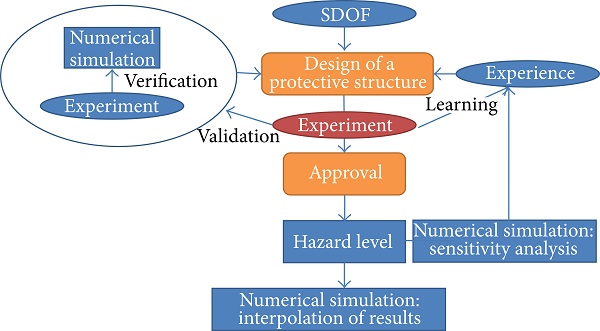
Even if there are several open questions in numerical simulations for blast-loaded laminated glass, there are strong reasons that they could help in the engineer’s work. The interaction between numerical simulations and their verification, validation, and the approval of a design by experiments can be described as shown in Figure 3.
Several other arguments can also be cited for employing numerical simulations in the protection design involving glass products.
Numerical simulations can help to understand the behaviour of the structure. While detailed experimental investigations are not easy to perform, numerical simulations can close that gap. Numerical simulations may help to develop new kind of materials or structures. These structures can be tested numerically before expensive experiments are conducted. Numerical simulations can help to investigate the different parameters of the windows for the design. When a set of experiments is conducted either to demonstrate the protection of the window or to validate the numerical simulation, the simulation can then be used to investigate, for example, other sizes of the glass sheets. In this way, experimental results can be extended to similar configurations by numerical simulations. Hence also the number of field experiments can be reduced by using numerical simulations.
While an experimental investigation captures mainly one scenario or even only one pressure-time curve representing that scenario, numerical simulations can be used to investigate a multiplicity of threat scenarios. The place of the charge and its size can be varied easily to see the influence of those parameters. Also much larger structures can be taken into account, like whole facades, and different types of facades could be tested, such as with steel-frame or cable-net supporting structures. Further, experimental investigations must be designed in advance to know the possible failure modes. Numerical simulations can support this process either to design a shock tube for testing windows or for designing the substructure for laminated glass in case of arena tests.
Undoubtedly, experimental research is needed in order to understand the physical phenomena when choosing the appropriate modelling techniques and material laws. Further dedicated material tests are needed to obtain relevant material parameters for the material models.
Apart from the more sophisticated finite element techniques, another numerical method is given by the single-degree-of-freedom oscillator method (SDOF), where the window is represented by a single mass and a special stiffness (Fischer [28, 29]). A large number of experimental results are used to get data in order to model the nonlinear stiffness properties of the spring. Obviously the SDOF method cannot replace experimental investigations for a more complex design.
2.2. Expectations from Numerical Simulations
European, ISO, and American testing standards for laminated glass windows (e.g., [15]) define a hazard level that is assessed and measured by the damage state of the glass pane and the position of the glass fragments that are found after the experiment behind the glass pane. More details can be found in US General Services Administration [30] and ISO standard [15] (Table 1) and also in [29, 31].
Table 1: Hazard-rating criteria for arena tests according to ISO 16933:2007 [15].
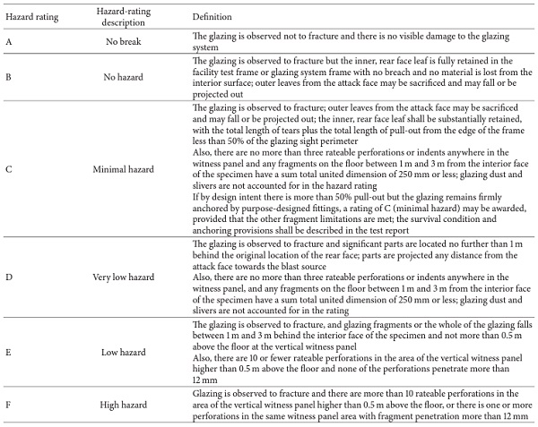
With respect to these criteria, scientific and technical literature has shown that numerical simulations can be used with confidence to determine the failure of the laminated glass and its interlayer and may be useful to approximate the launch conditions of the splinters [4]. The bearing capacity and the glazing damage level of the window of full window systems and their components could also be adequately determined by numerical simulations. However, the prediction of the formation and development of splinters or slivers of blast-loaded laminated glass has until now not been accurate enough and is a challenge for numerical simulations. Also the splinter velocity and dispersion behind the window cannot be determined numerically.
2.3. Selection of Representative Load Scenarios
The loading scenario depends on the specific protection requirements and local conditions. Detailed instructions for defining loading scenarios are given in national regulations or must be discussed with the infrastructure operator/owner or the responsible authorities. Attack scenarios to be considered in designing a structure are usually expressed in terms of equivalent mass of Trinitrotoluene (TNT) and stand-off distance, for example, the distance between the structure to be designed and the postulated explosion source. An indication of the size of the charge can be taken from [21]. Different TNT equivalents for other explosives like, for example, pentaerythritol tetranitrate (PETN), are given by [32].
In general, numerical simulations are able to handle an almost arbitrary loading scenario for the structural element considered. Taking these capabilities concerning loading into account, it is important to ensure that the modelled scenarios can be compared to the experimental results. For this, it would be necessary to capture the actual loading of the structural component examined with the same logic as in the experiments. Therefore, it is recommended to record in each simulation the resulting loading pressure and impulse for the considered structural elements, especially in calculations that combine fluid and structures.
2.4. Load Characterisation
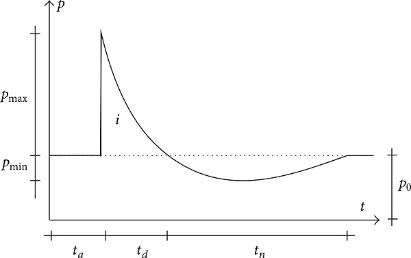
Blast waves are typically characterized by a compression phase, called overpressure (fast elevation of pressure above ambient pressure). This peak of overpressure is then followed by rarefaction waves inducing a negative phase during which the pressure falls below the ambient pressure. The compression phase starts with a strong increase in the pressure from the ambient pressure (Po) to the peak pressure (Po + Pmax) within a timescale of microseconds. Figure 4 shows a simplified form of the pressure history of a blast wave and indicates the relevant parameters. Some more descriptions of the parameters are given in [22, 33, 34]. Of importance for the loading of glass windows is also the negative phase since this could be strong enough to pull fragments that were developed by the positive phase outwards, particularly in combination with rebound effects.
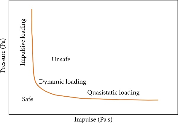
For a blast-loaded structure different loading conditions can be distinguished: impulsive, dynamic, and quasistatic loading (Figure 5). Loads with very short duration (relative to the structure’s natural period) are known as impulsive loading, and in laminated glass windows they often result in a shear failure next to the border or at the boundary itself. Loads with longer duration (dynamic loading) tend to cause bending mode failures of glass panels. Only very slowly developed pressures (quasistatic loading) would be simulated by using a static load. For the structure under consideration these loading regimes can be schematically shown in the so-called PI (Pressure-Impulse) diagram (Figure 5).
3. Key Input Parameters for the Numerical Simulation of Glazing Systems under Blast
3.1. Model Discretisation
Model discretisation is based on the transformation of real structural components in a numerical representation using finite elements. Elements are characterised by three main parameters:
(i)Element type (and degrees of freedom).
(ii)Number of nodes/element order.
(iii)Integration.
Some of the element types that are used in a stress analysis are presented in Figure 6 [35]. One of the main differences between those element types is their geometry. Elements may also be distinguished between solid elements, shell, beam, and truss elements.
![Figure 6 Some classical element types [35].](/sites/default/files/inline-images/Fig6_179.jpg)
Depending on the software used to assess the structural model of the glass system under study, different element types are available and can be employed. The number of degrees of freedom is associated with the element type and is the fundamental variable calculated during the analysis. For stress/displacement simulations the degrees of freedom may be translational and, for shell, pipe, and beam elements, translational and rotational.
Elements may be implemented as linear (first-order) or quadratic (second order) elements depending the number of nodes. Quadratic elements give a higher accuracy but by using more nodes per element. As a rule, the increase of the element order improves the accuracy of the result for the same element size. However, the increase of the element order increases the CPU time (calculation time). Generally, first-order elements perform better concerning wave propagation.
Numerical methods are used to integrate various quantities over the volume of each element. Elements can often be used in full or reduced integration, a choice that can have a significant effect on the accuracy of the element for a given problem. Use of reduced integration can also decrease the needed CPU time. Reduced integration is mainly used in order to reduce the locking of the elements. This could result in hourglass modes that should be avoided.
In modelling a window panel or a facade, the following issues should be taken into consideration:
(i)The geometrical shape of the window panel.
(ii)The design of the structure (laminated, multilayered, etc.).
(iii)The type of solver used to analyse the structure (explicit or implicit time integration).
(iv)Type of damage studied (brittle failure, delamination, etc.).
(v)Type of links between the structural components considered.
(vi)Boundary conditions.
The model discretisation for laminated glass is quite challenging. Several options ranging from single shell elements up to 3D solid elements are presented by Larcher et al. [20]. Depending on the question, a balanced model between accuracy and calculation time should be chosen.
An example of an insulated laminated glass panel and its frame is given in Figure 7. Additional information about simulations of insulated glass facades is given in [36].
3.2. Material Models
The appropriate material models should be chosen to best represent the material behaviour under the examined loading conditions and in compatibility with the model discretisation described in Section 3.1. The mechanical calibration of all window components should be carried out, depending on the glazing system typology, by taking into account the specific damage constitutive behaviour and possible strain rate-dependent phenomena.
Material models for the simulation of laminated glass windows and facades are usually based on the following theories:
(i)Linear behaviour with brittle failure limit (cracking).
(ii)Theory of plasticity with plastic flow rule.
(iii)Damage theory.
(iv)Viscoelastic and viscoplastic theory.
The choice of an appropriate theory depends on the specific application, that is, on the purpose of the simulation. In general the material model should be as simple as possible but as comprehensive as needed. Complicated material models need many material parameters that are not always available and these models are in addition sometimes more difficult to check.
3.2.1. Glass
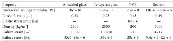
Glass is a typically brittle material. A linear elastic representation with failure or erosion criterion works well in most of the cases of technical interest. Sometimes, a plastic part is added in order to fade out the stress in a slower way and to also reduce numerical instability problems if such material model is not physical. The strain rate behaviour of glass is still not sufficiently investigated. First results show that the failure strength increases at very high strain rates [37]. Typical material parameter values for annealed as well as for tempered glass can be taken from [38, 39] and are given in Table 2.
Table 2. Typical material properties for glass, PVB, and sealant.
3.2.2. Interlayers
The material model for the PVB interlayer strongly depends on the considered damage level. Its behaviour until the first glass cracking can be assumed to be elastic since the strain is still very small. A more accurate description of the behaviour of the interlayer becomes important especially when the glass is cracked. Also a plastic material law could, for example, represent the loading behaviour under higher strain rates quite well when the unloading behaviour of PVB becomes more viscoelastic. Some values for the interlayer material are given in [20] and in Table 2.
3.2.3. Adhesives and Structural Sealants Joints
Adhesive joints and structural sealants are usually introduced between the glass panels and the metal frames. Literature references are available for their mechanical characterisation, for example, from the producers. In general, adhesives and sealants of common use in structural glass applications are typically characterised by low modulus of elasticity, limited tensile/shear resistance, and large ultimate strain. The simplest numerical modelling approach for the mechanical description of structural sealants in tension takes the form of equivalent linear elastic materials with brittle behaviour [40]. Some material data for sealants can be taken from data sheets of producers [41–43].
3.2.4. Steel and Aluminium Components
The strain rate effect of aluminium is generally small while that of steel could be high. Depending on the structural configuration, the strain rates in the bearing construction could be smaller. Nevertheless, a Johnson-Cook material law [44] could represent the strain rate and temperature behaviour of many metallic materials. Examples are given in [31].
3.3. Boundary Conditions
For the analysis of the blast response of a glass window or facade, FE numerical models should be properly validated and assessed not only in terms of mechanical characterisation of materials but also by properly taking into account all the main influencing parameters.
Specifically, careful attention should be given to the numerical modelling of each window component (e.g., glass panel, metal framework, and possible adhesive joints between them) and the connection to the building structure [9, 20].
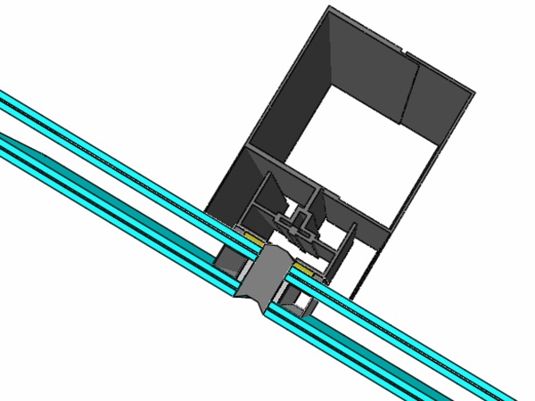
Both geometrically simplified models and computationally detailed models can be used, if properly validated for the specific case. An example of simplified models can be the description of a window in the form of 3D shell elements (glass panels), beam elements (metal frame), and mechanical point connectors (properly calibrated so that they could adequately reproduce the physical interaction between the glass panel and the frame). The same modelling approach can be extended to glazing systems in general, namely, consisting of curtain wall modular units, cable-net systems, and metal point connectors for the glass panels (Figure 8).
![Figure 8 Example of point-supported glass panel. (a) Typical “spider” connector and (b) corresponding geometrically simplified FE model [45].](/sites/default/files/inline-images/Fig8_139.jpg)
The appropriate numerical description of each window component should be suitably checked and validated against simple analytical models or experiments derived from small specimens/single facade components.
Before performing dynamic analyses on full 3D solid FE models, careful consideration should be given to the assessment of the correct description of adhesive joints and/or mechanical connectors. Regarding the boundary conditions of the FE models, the presence of special devices/connection systems or brackets between the glazing window and the structural system (e.g., the concrete slab of a building) should be properly taken into account, so that the accuracy of the predicted effects due to the design blast load on glass as well as the maximum reaction forces transmitted to the substructure can be ensured.
3.4. Load Application
The numerical approaches can be divided into two main groups: coupled and uncoupled calculation approaches. A coupled approach may be needed in a case where the structure-fluid interaction is substantial, for example, in the case of a very flexible structure, isolated glass, fragment trajectories, and openings in the glass. In general, the loading definition is based on the TNT-equivalent method. In any case, the notion of TNT equivalent must be used carefully: the method for determining the TNT equivalent, the charge geometry, and the range of validity must be specified [46].
3.4.1. Uncoupled Approach
Pressure caused by blast waves can be calculated according to the theory of normal and oblique shock wave reflection, where the parameters of the spherical blast wave are estimated from empirical equations or diagrams (e.g., Kinney and Graham [23], Kingery and Bulmash [22]). These load functions can be employed if there are no alterations of the propagating blast wave between the detonation point and the studied structure (due to terrain anomalies, other obstructions, etc.). Clearly this method considers exclusively the dynamic behaviour of the structure (and not the surrounding air), and its advantage is the much lower computational cost.
3.4.2. Coupled Approach
More comprehensive explosion simulations use an Arbitrary Eulerian-Lagrangian (ALE) simulation scheme. In ALE the explosive and surrounding air are modelled using an Eulerian approach, typical in fluid mechanics. The behaviour of both gaseous materials is modelled using Equation-of-State (EOS) models that relate the pressure to the density of the material and internal energy. For air, this is typically the ideal gas law and for explosives, such as TNT, a Jones-Wilkins-Lee (JWL) model can be used [29]. The structure subjected to the blast loads is modelled using the traditional Lagrangian approach. The coupling between the Eulerian and Lagrangian elements is included, so that the solid Lagrangian structure occupies Eulerian space and pressures on the interface act as loads on the solid structure. In comparison to the uncoupled approach, the results may describe the blast propagation much better as soon as the elements are small enough. Especially, in case of multiple reflections, channelling or shadowing the coupled approach must be used. The calculation time of this procedure is in general much longer since it depends on the detonation process that has a very short characteristic time.
3.5. Sensitivity Study for Essential Calculation Parameters
The topic of sensitivity study is broad and can cover a lot of aspects. This section focuses on some important parameters to be analysed such as
(i)mesh size definition and shape of the elements,
(ii)parameters for material modelling.
3.5.1. Mesh Size Definition and Shape of Element
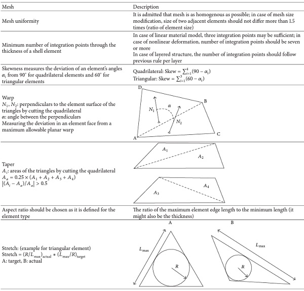
Some recommendations have been written in [29, 31], and Table 3 presents typical parameters to be checked before and during the simulation. Most numerical codes provide their own quality checks that might help engineers to design the numerical model.
Table 3. Mesh conformity recommendations for shell and solid elements (see also [16]).
After the element quality check, a mesh sensitivity study should be performed by using models with different mesh refinement and comparing the main results, such as failure location and size, maximum deflection of the structure, and maximum strain (plastic strain) value. At least two different mesh refinements should give similar results in order to minimise mesh sensitivity.
Another way to guide the mesh generation is to evaluate where the highest stress values occur and then to verify that the mesh size is able to model the gradient of these stresses. If the gradient is too steep, it can generate a wrong estimation of maximum stress value. A general example of mesh convergence is given in [47].
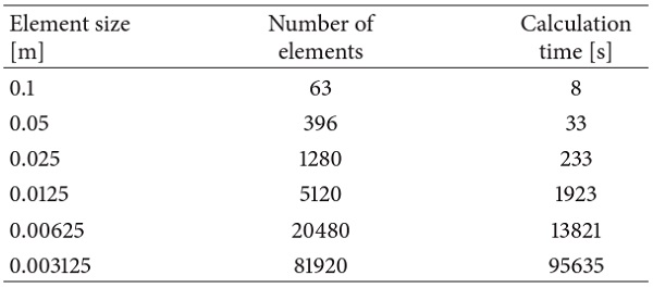
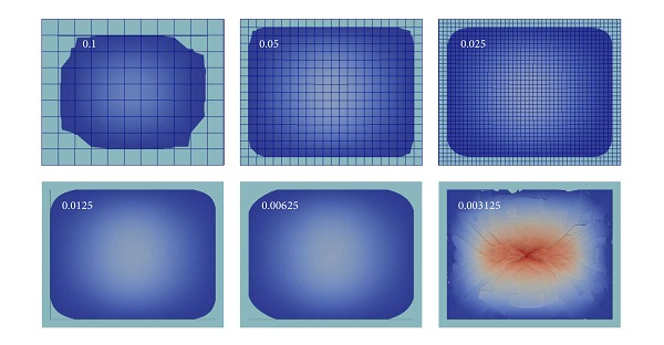
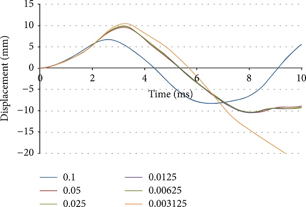
An example of local discretisation is given below, representing a blast-loaded laminated glass plate similar to the experiment of Kranzer et al. [18]. The simulation is done by using EUROPLEXUS [48] in the same way as proposed by Larcher et al. [20] using layered elements (linear) through the thickness. The glass plate is clamped between two steel frames, as defined by ISO 16933, where elastic stripes are placed between the steel frame and the glass. The element sizes, the number of elements, and the calculation time are given in Table 4. The results obtained (Figures 9 and 10) show that the coarsest mesh results in a different displacement history. This may be due to the extended boundary conditions for the coarsest mesh where the elastic stripe is wider. Only the finest mesh manages to represent the failure behaviour of the laminated glass as indicated by the experiment. The displacement history is also quite different for the finest mesh size in respect to the coarser mesh sizes, especially in the rebound phase.
Table 4. Mesh sensitivity analysis for a blast-loaded laminated glass.
3.5.2. Parameters for Material Modelling
The choice of a material model defines the number of input parameters. For example, for a purely elastic material (such as glass) with a stress limit, the material parameters needed for the analysis would be
(i)Young’s modulus,
(ii)Poisson’s ratio,
(iii)density (due to dynamic structure response),
(iv)stress elastic limit.
In many cases, the number of material parameters is much bigger. For example, the number of parameters for the Johnson-Cook plasticity model [44] (strain rate and temperature-dependent model including failure) is generally six. Typically, the more “advanced” the material model is, the more the input parameters needed are.
In order to evaluate the influence of each material parameter, it is useful to determine the degree of uncertainty of the value of the material parameter. Then, an option is to generate a sensitivity analysis on each material parameter in order to check its influence on the results.
Different mathematical approaches can be used in order to solve this type of problem. Based on an iterative process, several simulation codes provide a numerical approach to conduct this type of analysis (optimisation problem).
3.6. Failure, Fracture, and Erosion
As soon as the after-breakage behaviour must be modelled, the failure mechanisms of the glass, the interlayer, and the framing become important. The failure behaviour of glass is brittle. The failure results in fracture of the material, and numerically several methods can be applied in order to describe such effect. Most appropriate in the explicit finite element method is the erosion. Elements where the failure criterion is reached are removed from the element table and are not any more considered in the calculation. The removed mass must be controlled or moved to the neighbouring elements. The crack width is defined by the element size and therefore either small elements must be used from the beginning of the simulation or additional element splitting methods or adaptivity [49] can be used. Other possibilities are given by the element-free Galerkin method or extended finite element method (XFEM) or direct splitting of the elements.
4. Validation and Assessment of Performance
4.1. Validation of Numerical Models
The numerical method and the material model should be validated by experimental data. This validation should include the following:(i)Basic material tests are, namely, intended for the proper mechanical characterisation of glass and the other window components (e.g., interlayers in presence of laminated glass and frames, adhesive joints, and mechanical connectors). Basic material testing would be appropriate even if this is in most cases neither possible nor cost efficient. Data from literature or from the manufacturers of the products could replace the material tests.(ii)Structural tests: the individual glazing window components (glass pane, frame, and connectors), as well as their corresponding structural interaction, should be sufficiently validated.(iii)A mesh sensitivity study: it must be performed, as outlined above, in order to validate the model.
The objective of a nonlinear analysis is to simulate the structural behaviour and to determine the structural resistance. Such task can also be formulated as a prediction of the most probable resistance, which would then be the mean value of ultimate resistance. Therefore, the mean resistance is chosen as a reference for safety assessment by nonlinear analysis. The uncertainty due to random variation of material properties (and possibly of other parameters of resistance) can be described by the random variation of resistance. In addition a model uncertainty must be included separately.
4.2. Examples for Validation Experiments from Literature
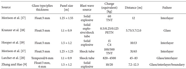
In order to validate numerical models experimental data are needed. Appropriate experiments are not often available in advance. Table 5 includes some sets of experiments, published in the open literature, which could be used for the model development and validation in this field.
Table 5. Blast-loaded laminated glass experiments published in the open literature.
4.3. Assessment of Performance
The interpretation of the results can be done in several ways. A damage parameter or failure limit together with an erosion criterion can identify cracks in the glass, in the interlayer, or in the other structural components. A simulation resulting in a completely undamaged state can be identified as a full protection, without any glass splinters in the interior. Assuming a model that can represent the failure of the interlayer is available, for simulation resulting in an undamaged interlayer, it can be stated that the interior of the room is protected from major glass splinters. Also the window failure can be distinguished between shear failure near the window borders and bending failure in the middle of the pane. Finally, point connectors may have a different local failure mechanism. The interacting force between anchors/links and the surrounding structures should also be checked in order to avoid their failure.
4.4. Numerical Simulation Domains of Application regarding Actual Standards
Table 1 shows the hazard levels that are normally established experimentally. They represent in a way the formation and projection of splinters or fragments behind a laminated glass window. The fragmentation of laminated glass cannot yet be represented very well by numerical simulations. Therefore, with regard to hazard levels, numerical simulations can only be seen as a supplement to the experimental investigations.
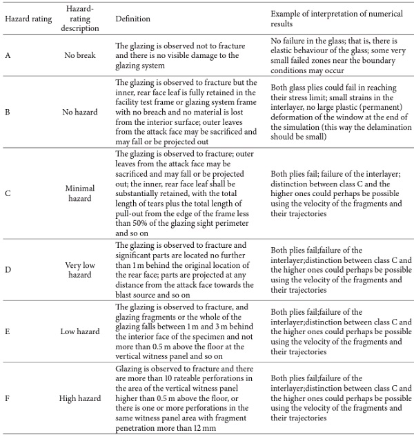
Concerning specifically the hazard levels in ISO 16933:2007 [15], an idea of proposal for interpreting numerical simulation results and of corresponding them to the hazard levels A, B, and C can be drawn, as indicated in Table 6. Eventual developments of calculation methods and models should enable more reliable results and their assignment to higher hazard levels, too.
Table 6. Hazard-rating criteria for arena tests according to ISO 16933:2007 [15].
5. Conclusions
A review has been made on the abilities of numerical simulations to assess blast-loaded laminated glass windows and facades and to be used under certain circumstances to determine related hazard levels.
As emphasised, special attention should be given to the validation of numerical models, since the choice of loading conditions, material parameters, and boundary configurations could have strong influence on the results. In particular, this review paper presents the first steps of an ongoing activity towards European standardization in that field. The next step would be to further elaborate these findings and discuss them with the responsible technical committees of the relevant EN and ISO standards.
Competing Interests
The authors declare that they have no competing interests.
Acknowledgments
The research leading to these results received funding from the European Union within the European Reference Network for the Critical Infrastructure Protection (ERNCIP) project hosted at the Joint Research Centre (JRC), European Commission, Via E. Fermi 2749, Ispra, Varese (VA), Italy.
References
- H. S. Norville, N. Harvill, E. J. Conrath, S. Shariat, and S. Mallonee, “Glass-related injuries in Oklahoma City bombing,” Journal of Performance of Constructed Facilities, vol. 13, no. 2, pp. 50–56, 1999. View at: Publisher Site | Google Scholar
- M. Larcher, R. Forsberg, U. Björnstig, A. Holgersson, and G. Solomos, “Effectiveness of finite element modelling of damage and injuries for explosions inside trains,” Journal of Transportation Safety & Security, vol. 8, supplement 1, pp. 83–100, 2015. View at: Publisher Site | Google Scholar
- G. Balssa, G. Panofre, J. F. Hurstel, J. Bez, C. Capdevielle, and V. Sciortino, “Explosion de l’usine AZF de toulouse: description des lésions prises en charge au titre d’accident du travail par la Caisse primaire d’assurance maladie de la Haute-Garonne,” Archives des Maladies Professionnelles et de l'Environnement, vol. 65, no. 6, pp. 463–469, 2004. View at: Publisher Site | Google Scholar
- G. Valsamos, F. Casadei, M. Larcher, and G. Solomos, “Implementation of flying debris fatal risk calculation in EUROPLEXUS,” Tech. Rep. JRC94805, Joint Research Centre, Publications Office of the European Union, Luxembourg, Luxembourg, 2015. View at: Google Scholar
- Johannesen, https://www.flickr.com/photos/nhd-info/5980529033/in/photostream.
- R. Müller and M. Wagner, “Berechnung sprengwirkungshemmender Fenster- und Fassadenkonstruktionen,” Der Bauingenieur, vol. 81, no. 11, pp. 475–487, 2008. View at: Google Scholar
- M. Timmel, S. Kolling, P. Osterrieder, and P. A. Du Bois, “A finite element model for impact simulation with laminated glass,” International Journal of Impact Engineering, vol. 34, no. 8, pp. 1465–1478, 2007. View at: Publisher Site | Google Scholar
- D. Sun, F. Andrieux, A. Ockewitz, H. Klamser, and J. Hogenmüller, “Modelling of the failure behaviour of windscreens and component tests,” in Proceedings of the 5th European LS-DYNA Users Conference, May 2005. View at: Google Scholar
- X. Zhang and H. Hao, “Fragmentation characteristics of tempered glass windows under air blast wave,” in Proceedings of the 3rd International Conference of Protective Structures (ICPS '15), Newcastle, Australia, 2015. View at: Google Scholar
- S. J. Bennison, A. Jagota, and C. A. Smith, “Fracture of glass/poly(vinyl butyral) (Butacite) laminates in biaxial flexure,” Journal of the American Ceramic Society, vol. 82, no. 7, pp. 1761–1770, 1999. View at: Publisher Site | Google Scholar
- H. D. Hidallana-Gamage, D. P. Thambiratnam, and N. J. Perera, “Design guidance for blast-resistant glazing,” Journal of Architectural Engineering, vol. 21, no. 3, Article ID 4015003, 2015. View at: Publisher Site | Google Scholar
- A. Burmeister, “Moderne fassaden-explosionsschutz,” in Glas im konstruktiven Ingenieurbau, Hochschule München, Munich, Germany, 2008. View at: Google Scholar
- J. Pelfrene, J. Kuntsche, S. Van Dam, W. Van Paepegem, and J. Schneider, “Critical assessment of the post-breakage performance of blast loaded laminated glazing: experiments and simulations,” International Journal of Impact Engineering, vol. 88, pp. 61–71, 2016. View at: Publisher Site | Google Scholar
- X. Zhang, H. Hao, and G. Ma, “Parametric study of laminated glass window response to blast loads,” Engineering Structures, vol. 56, pp. 1707–1717, 2013. View at: Publisher Site | Google Scholar
- ISO 16933:2007/cor1, “Glass in building-explosion-resistant security glazing-test and classification for arena air-blast loading,” 2008. View at: Google Scholar
- SDRC, IDEAS Simulation: Finite Element Modelling User's Guide, Siemens Product Lifecycle Management Software, 2014.
- C. Morison, M. Zobec, and A. Frenceschet, “The measurement of PVB properties at high strain rates, and their application in the design of laminated glass under bomb blast,” in Proceedings of the International Symposium on Interaction of the Effects of Munitions with Structures (ISIEMS '07), Orlando, Fla, USA, September 2007. View at: Google Scholar
- C. Kranzer, G. Gürke, and C. Mayrhofer, “Testing of bomb resistant glazing systems. Experimental investigation of the time dependent deflection of blast loaded 7.5 mm laminated glass,” in Proceedings of the Glass Processing Days, Tampére, Finland, June 2005. View at: Google Scholar
- P. Hooper, J. Dear, B. Blackman, D. Smith, D. Hadden, and R. Sukhram, “Strength of structural silicone glazing joints under blast loading,” in Proceedings of the Department of Defense Explosives Safety Board Seminar, Palm Springs, Calif, USA, August 2008. View at: Google Scholar
- M. Larcher, G. Solomos, F. Casadei, and N. Gebbeken, “Experimental and numerical investigations of laminated glass subjected to blast loading,” International Journal of Impact Engineering, vol. 39, no. 1, pp. 42–50, 2012. View at: Publisher Site | Google Scholar
- NATO, STANAG 2280: Design Threat Levels and Handover Procedures for Temporary Protective Structures, NATO, 2008.
- C. N. Kingery and G. Bulmash, “Airblast parameters from TNT spherical air burst and hemispherical surface burst,” Tech. Rep. ARBRL-TR-02555, Defence Technical Information Center, Ballistic Research Laboratory (BRL) at Aberdeen Proving Ground, Maryland, Md, USA, 1984. View at: Google Scholar
- G. F. Kinney and K. J. Graham, Explosive Shocks in Air, Springer, Berlin, Germany, 1985.
- United States Department of Defense, Unified Facilities Criteria, UFC 3-340–2, United States Department of Defense, Virginia, Va, USA, 2008.
- D. Bogosian, J. Ferritto, and Y. Shi, “Measuring uncertainty and conservatism in simplified blast models,” in Proceedings of the 30th Explosives Safety Seminar, Atlanta, Ga, USA, 2002. View at: Google Scholar
- M. Larcher and F. Casadei, “Explosions in complex geometries—a comparison of several approaches,” International Journal of Protective Structures, vol. 1, no. 2, pp. 169–196, 2010. View at: Publisher Site | Google Scholar
- M. Larcher, A. Stolz, L. Rüdiger, and M. Steyerer, “Statische Ersatzlasten und ‘Ingenieurverfahren’,” in BauProtect, N. Gebbeken, K. Thoma, and M. Klaus, Eds., pp. 117–130, Universität der Bundeswehr München, 2012. View at: Google Scholar
- K. Fischer and I. Häring, “SDOF response model parameters from dynamic blast loading experiments,” Engineering Structures, vol. 31, no. 8, pp. 1677–1686, 2009. View at: Publisher Site | Google Scholar
- A. van Doormaal, C. Haberacker, G. Hüsken et al., “Numerical simulations for classification of blast loaded laminated glass: possibilities, limitations and recommendations—ERNCIP Thematic Group: resistance of structures to explosion effects,” Tech. Rep. JRC94928, Publications Office of the European Union, 2014. View at: Google Scholar
- US General Services Administration, “Standard test method for glazing and window systems subject to dynamic overpressure loadings,” Tech. Rep. GSA-TS01-2003, 2003. View at: Google Scholar
- A. Stolz, A. van Doormaal, C. Haberacker et al., Resistance of Structures to Explosion Effects: Review Report of Testing Methods ERNCIP Thematic Area Resistance of Structures to Explosion Effects. Deliverable D1, Publications Office of the European Union, 2013.
- D. Hyde, “ConWep, US Army Waterways Experimental Station, US Army,” 1991. View at: Google Scholar
- M. Larcher, “Pressure-time functions for the description of air blast waves,” Tech. Rep. JRC46829, Joint Research Centre, Ispra, Italy, 2008. View at: Google Scholar
- V. Karlos, M. Larcher, and G. Solomos, “Analysis of the blast wave decay coefficient in the Friedlander equation using the Kingery-Bulmash data,” Tech. Rep. JRC94784, Joint Research Centre, Ispra, Italy, 2015. View at: Google Scholar
- K.-J. Bathe, Finite Element Procedures, Prentice Hall, Englewood Cliffs, NJ, USA, 1996.
- R.-B. Deng and X.-L. Jin, “Numerical simulation for blast analysis of insulating glass in a curtain wall,” International Journal for Computational Methods in Engineering Science and Mechanics, vol. 11, no. 3, pp. 162–171, 2010. View at: Publisher Site | Google Scholar
- M. Peroni, G. Solomos, V. Pizzinato, and M. Larcher, “Experimental investigation of high strain-rate behaviour of glass,” Applied Mechanics and Materials, vol. 82, pp. 63–68, 2011. View at: Publisher Site | Google Scholar
- C. Morison, The resistance of laminated glass to blast pressure loading and the coefficients for single degree of freedom analysis of laminated glass [Ph.D. thesis], Cranfield University, 2007.
- C. Louter and J. H. Nielsen, “Numerical analyses of the effect of SG-interlayer shear stiffness on the structural performance of reinforced glass beams,” in Proceedings of the COST Action TU0905 Mid-Term Conference on Structural Glass, pp. 405–412, April 2013. View at: Google Scholar
- D. C. Weggel and B. J. Zapata, “Laminated glass curtain walls and laminated glass lites subjected to low-level blast loading,” Journal of Structural Engineering, vol. 134, no. 3, pp. 466–477, 2008. View at: Publisher Site | Google Scholar
- Dow Corning, “Product information Dow Corning 895, structural glazing sealant, one-part silicone rubber,” 2011. View at: Google Scholar
- Bostik, “PrV-70 high strength structural glazing silicone adhesive sealant,” Technical Data Sheet, Bostik Australia, 2008. View at: Google Scholar
- Henkel, “Pattex SL 690 solyplast-structural glass,” 2012. View at: Google Scholar
- G. Johnson and W. Cook, “A constitutive model and data from metals subjected to large strains, high strain rates and high temperatures,” in Proceedings of the 7th International Symposium on Ballistics, The Hague, Netherlands, 1983. View at: Google Scholar
- C. Amadio and C. Bedon, “Viscoelastic spider connectors for the mitigation of cable-supported façades subjected to air blast loading,” Engineering Structures, vol. 42, pp. 190–200, 2012. View at: Publisher Site | Google Scholar
- P. M. Locking, “The trouble with TNT equivalence,” in Proceedings of the 26th International Symposium on Ballistics, Miami, Fla, USA, 2011. View at: Google Scholar
- L. Champaney and L. Gendre, “Science de l'ingénieur: Raffinement du maillage et convergence,” Tech. Rep., 2012. View at: Google Scholar
- Joint Research Centre and Commissariat à l’énergie Atomique et aux énergies Alternatives, EUROPLEXUS, http://www-epx.cea.fr/.
- F. Casadei, M. Larcher, and G. Valsamos, “Adaptivity in shell/beam/bar elements in EUROPLEXUS,” Tech. Rep. EUR 26697, JRC90456, Publications Office of the European Union, Luxembourg, Luxembourg, 2014. View at: Google Scholar