Source:
Challenging Glass 7
Conference on Architectural and Structural Applications of Glass
Belis, Bos & Louter (Eds.), Ghent University, September 2020.
Copyright © with the authors. All rights reserved.
ISBN 978-94-6366-296-3, https://doi.org/10.7480/cgc.7.4607
Authors:
Chris Noteboom - Arup
Peter Lenk
Iris Rombouts
Erik van der Thiel

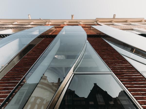
A bespoke structural glass storefront is designed for the P.C. Hooftstraat 138. Developer Warenar Real Estate assembled a design team with UNStudio, Arup and Octatube. The façade features twisted geometries with precisely detailed glass connections and custom non-orthogonal steel and glass doors. At ground floor level the facade starts flush with adjacent buildings but rising up it also leans and cantilevers outwards to become more visible from a distance.
For optimal quality and minimalistic detailing, a scheme was designed in which most elements could be pre-assembled in the factory into three large 2m x8,5m high units. Connections between curved glass elements are all glued in combination with stainless steel elements for edge protection and emphasis on the curved geometry.
Risk of thermal breakage of annealed curved elements that are partially inside and partially outside is minimized by gluing stainless steel plates to the glass elements that act as cooling ribs. Frequent collaboration throughout the whole project between all parties resulted in successful delivery with no glass breakage during the construction phase. It took years to design, months to assemble in factory, but only 2 days to construct on site.
1.Introduction
1.1.Timeline and basic project information
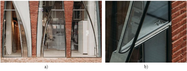
In December 2019 the façade of the P.C. Hooftstraat 138 was officially revealed to public. The developer Warenar Real Estate assembled a diverse team of specialists to build another high quality and innovative façade after their widely published Crystal Houses Project (Oikonomopoulou et al.2016). UNStudio was asked as the architect to design a special jewel to improve the architectural quality of this side of the P.C. Hooftstraat; the most exclusive shopping street of Amsterdam. This jewel is now named as The Looking Glass.
The design of the façade resembles curves found in textiles and featured mainly curved glassfrom the start. The ground, first and second floor parts of the façade were split in three in line with the historic identity of the street and thus three vertical strips of façade can be distinguished. The trichotomy in the façade is not only architectural but was also used as guiding principle for structure and construction. Some of the nicknames for the façade refer to this multiplicity, such as ‘three giant iPhones’ or ‘swiss watches’.
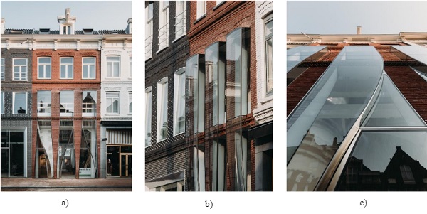
This paper focusses on the special glass part of the façade that covers both the ground floor as well as the first floor with a total height of 8.5 m and width of 6.5 m. It features various unique curved glass panels and structurally bonded stainless-steel elements. At ground level the facade starts flush with adjacent buildings but rising up it also leans and cantilevers outwards to become more visible from a distance.
Arup was asked in February 2017 to provide façade engineering services and so to collaborate with UN Studio to progress the technical design and to realize the dreams and ambitions. After various design and industry consultation meetings, details and calculations supporting tender documents were produced. Three international high-quality façade contractors were asked to bid for the PCSA and construction at the end of 2017.
Unfortunately, the curved and unique nature resulted in a significant cost increase for the developer and thus a value engineering phase was started in the beginning of 2018. Multiple design proposals were discussed and after choosing one, Octatube was incorporated into the design team to help optimize and eventually construct the design to agreed budget. A nearly invisible glass division was introduced at the first level and the geometry was modified in such a way that only single-curved glass elements were required.
At the end of 2018 a refined design was produced and preliminary discussed with the municipality of Amsterdam, before submitting documents in February 2019to obtain a building permit.Production of the glass at Cricursa in Spain started soon afterwards. Construction in the factory of Octatube started immediately. The pre-assembled units were installed on site in only two days in May 2019. Brickworks with acertified adhesive connection to insulation together with the final finishing of the façade works took place in August 2019.
1.2.Curved glass
Architecture is a constantly developing field with new trends emerging while old trends are fading, transforming and re-appearing again. In the past decades, designers fully embraced complex geometrical forms, predominantly due to the advances in parametric and computational design. All main players in the construction industry responded to this demand relatively swiftly, successfully constructing projects with undulated forms in structural steel, concrete or timber.
Nowadays, new trends in robotic and additive manufacturing technologies are pushing this boundary even further. In glass design, rectangular minimalistic architecture was very prominent in the past years, fully embracing advances in glass technology. Recently, the trend of complex geometries can also be seen in glass facades. Each realized project acts as a reference and catalyst for more change.
In theory, glass as “solidified fluid” should be an excellent material to explore and support current trends in contemporary architecture, fueled by parametric modelling. Cost of glass components is driven by the number of processes a glass product needs to undergo and limited by the current capabilities of manufacturing machinery. Possibilities to explore forms are reliant on individual skills and experience, perhaps a distant remainder of the former glory of Venetian and Bohemian artisan glass masters of the past.
During the design process of The Looking Glass, all possible ideas to get to the required shape were investigated, such as conventional methods of slumped annealed and chemically toughened. Or simplifying geometry to fit within a cylindrical shape which will be then possible to bend during tempering. We were also experimenting with an idea of cold bending techniques during the lamination with potentially additional cold bending in situ.
Similar concepts were used in the Bombay Sapphire greenhouse, UK (Lenk et al.2018) or the Van Gogh museum in Amsterdam (Bijster et al.2015). Due to the complexity of the geometry, desired visual quality, tight tolerances and the proposed detailing, slumped annealed glass was recommended. Visible clamp plates on the outside were architecturally undesirable which in turn meant in situ cold bending was not an option. Cold bending during lamination was considered as too specialized with commercial disadvantages.
2. Conceptual and schematic design
2.1.Geometry curved glass and interaction with industry
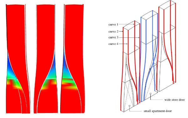
The design of the façade is special because of its geometry. The façade consists of three steel and glass boxes that have a similar geometry. Four main 3d curves define the main geometry of one unit, see Figure 2. Two curves (1 and 2) that define the inside edge of the façade box are relatively simple as they are planar curves and only bend in the plane of façade. The two front curves (3 and 4) are more complex and start narrow at the bottom to provide space for doors and then bend both outwards in the plane of the façade and out of the façade.
At the bottom, the distance between curve 1 and 3 is 250 mm and at the top 500 mm; the façade cantilevers 250 mm outwards at the top to become visible from a distance. Figure 2a shows an initial analysis of the surface minimal radius when the façade featured twisted glass elements, just above the door openings. However, after consultation with various glass industry parties, it was concluded that such glass components were theoretically possible to fabricate but provided significant risk to the project program as well as a cost increase.
The minimum radius was smaller than 0.5 m and thus very curved. To rationalize the façade geometry the doors were made flat and the twisted element was substituted by one flat element and one curved element. The feedback from the industry also provided the design team with the following design rules:
a) don’t use beveled edges with curved glass elements;
b) account for a theoretical tolerance on curved glass of 1 mm per meter;
c) design for a minimum of 250 mm width for the big curved front pane (minimum distance between curve 3 and 4).
The recommendations were incorporated in the geometry and design of the details. Also, a glass division was introduced at first floor level to reduce the height of the panels from over 8 m to over 5 m. This reduced production tolerances and would enhance minimalistic detailing. Another advantage of the ‘cut’ was that the top part of the façade would only consist of flat elements.
2.2. Structural concept
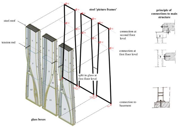
To create the façade with three steel and glass boxes with curved glass and multiple glass joints, that also cantilevers outwards, a structural concept was introduced for the unit that can be divided in three main components. This is also visualized in figure 3.
The first component is the connection to the main structure of the building. The building was completely rebuilt to include a new basement and floor levels. The basement structure is made of in situ concrete with an integrated, outwards cantilevering horizontal part providing a stiff support for the façade. The superstructure is made of steel with concrete floors. Deflections of the main structure were provided by the main structural engineer of the building: Brouwer & Kok. To allow differential (vertical) settlements of the floors it was decided to only support the façade vertically at the bottom. Horizontal supports in and out of the plane of the façade were designed at the first and second floor, matching the glass divisions. Connections were designed as steel brackets anchored to the concrete, allowing execution tolerances.
The second component of the structural concept of the façade is the steel frame around the glass box. A so called ‘picture frame’ concept was discussed during a design review at Arup that would allow for a pre-assembled glass box. The frame is made of rectangular hollow sections (RHS), measuring 120 mm x 60 mm x 8 mm. Glass is connected to the steel frame and the steel frame is connected to the brackets and is used during transportation and construction. The supports and brackets for the doors were also connected to this frame. After positioning the frame at the construction site and connecting it to the brackets, a few extra connections in between ‘picture frames’ were made as well, to specifically increase stiffness for the door connections with long brackets.
The third and most complex component of the structural concept of the façade is a hybrid stainless steel and glass box, connected to the ‘picture frame’ fully assembled in factory. It is a hybrid box as the main structural elements are glass, but stainless steel elements wrap all around the glass, provide extra stiffness around door openings, and are used for connections. A modern version of stained glass windows, but now curved and with stainless steel and structural silicone (DC993).
The largest glass elements are the front panels (#1 and #2 in figure 3) of which the top one (#1) is vertically supported by the bottom one (#2). Panel #2 is pinned and supported at the bottom.Ithas eccentricities in both x-and y-directions due to the façade geometry. Eccentricity in x-direction (in the plane of the façade) is solved by connectingthe panel to the door frame and eccentricity in y-direction (out ofplane of the façade) is solved by the structural silicone connection to the side panels.
At the top of the façade a curved steel roof element also provides support in x-direction for the top panel. So-called ‘J-panels’ (#7 and #8) are connected to the door frame and restrained by an extra hidden steel rod in the joint to glass panel #4. Stainless steel plates are glued to the side panels (#4 and #5) by means of structural silicone to which local steel connections to the perimeter frame are bolted. Front panels (#1 and #2) are structurally glued to the side panels with stainless steel in between.
2.3.Structural analysis of the global system
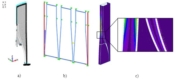
The structural analysis of the façade was done via multiple models with varying complexity. Glass thickness was chosen with sufficient thickness (2 x 12 mm) for silicone connections and stiffness near door openings was carefully assessed. In the beginning of the design process separate models of the glass elements were made with a focus on the front elements with eccentric supports (#1 and #2 in fig 3).
In figure 4 examples of models can be seen, made by both Arup and Octatube. The front pane is loaded by wind perpendicular to the surface and in plane of the surface as the façade cantilevers outwards. Dead load of the top panel is transferred to the bottom one and due to curvatures vertical and horizontal reaction forces result. Stiffness of structural silicone and steel perimeter frame was included in the glass assessments.The steel frames are also checked by applying wind loads directly and reaction forces are used to design and check the brackets.
Structural silicone was checked via detailed connection models as can be seen in the next paragraph, but also with hand calculation checks according to the Dow Corning guidelines.
2.4. Adhesive connections
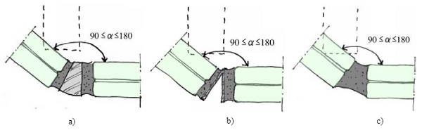
In the initial design phase, a glass corner detail was developed by the design team with stainless steel sections at the full corner. The stainless steel bar is then purely an aesthetic component, not adding any strength nor stiffness to the structural system. However, it does enhance the resilience of the system: by protecting the vulnerable glass edge. Especially in the first stage of the design, the geometry of the stainless steel sections would be very complex, as twisted glass elements resulted in a varying angle of the corner detail as shown in figure 5.
Two investigated manufacturing techniques were 3d printed sand molds with casted and milled steel bars. Glass corners were proposed as structural joints transferring shear and tension between the glass planes. A nominal bending moment was expected in the joint due to the geometrical complexity and resulting eccentricates. Structural silicone was selected as an adhesive with a long track record that justifies its capabilities in addition to well understood installation limitations as well as required quality control to ensure satisfactory bond.
Relatively low (dynamic) design stresses for two component DC 993 are prescribed by the manufacturer: 0.14 MPa. However, real (tensile) strength is much higher. During durability testing, representing 50 years of weathering, the initial tensile strength of 1.59 MPa only lowered to 1.52 MPa (Dow Corning, 2019). This is good as the connection detail would be exposed to rain, sun and differences in temperature.
The silicone would also be able to accommodate tolerances between the curved glass and stainless steel which were specified as +/-2mm in all directions., Structural silicone was already applied in other projects, such as the Van Gogh Museum in Amsterdam (Bijster et al., 2016). This would help in discussions with public authorities to obtain a building permit without significant prolongation of the construction program due to the verification tests.
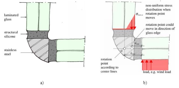
The challenge with the structural silicone detail was that due to eccentricities in the corner, bending stresses would occur in the silicone. In figure 6the detail is presented and eccentricities are discussed at the right.
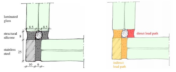
After further development of the detail and a period of value engineering for the structural glass façade, the solid section was changed to a flat steel plate. The double curved geometry of some glass elements was simplified to single curved glass elements. That also meant that the complexity of the flat steel section was reduced and as such would be easier to manufacture. A curved strip was cut out of a flat plate and afterwards bent in one direction to create a doubly curved strip. Changing the detail to flat steel meant also that a direct load path could be introduced into the detail.
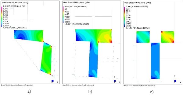
Only the direct load path would be considered later, however it was investigated what the stresses would be if the entire joint would be filled with structural silicone. Figure 8 shows the results of a comparison without and with space for a backer rod as 3-point gluing was not preferred due to risk of breakage.
Silicone joints are exposed to a variety of loads: dead load, wind on front panel, wind on side panel and thermal expansion. Especially the dead load component was carefully examined as due to the complex geometry and relatively high longitudinal stiffness of the joint, stresses were predicted in the silicone by global analysis. Long term stress in silicone was minimized by choosing relative thick glass with a stiff (SG) interlayer as well as with fabrication sequence.
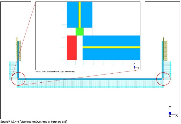
Project specific detailing required detailed examination of the structural behavior of the adhesive connection. Plain strain numerical model of the typical cross section was analyzed as presented on figure 9. All components of the connection were explicitly modelled. 8-Node quadrilateral quadratic elements with a mesh density of 0.5 mm was considered to subdivide zone modelling adhesive connection, this was based on convergence study which is not part of this paper.
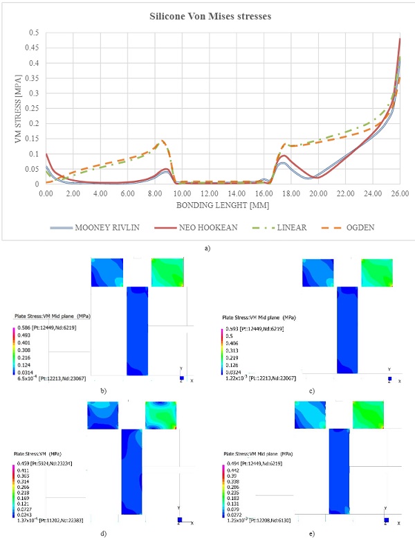
Comparative study is presented where structural silicone is modelled as:
- Linear elastic material with E = 4 MPa, G = 0.67 MPa, v = 0.49 (two different models are required if tension and shear are assessed);
- Neo Hookean model with C = 0.67 MPa;
- Mooney Rivlin model with C1 = 0.33 MPa and C2 = 0.005 MPa;
- Ogden with C = 0.71938 MPa, α = 1.9225.
All material models were extracted from the published literature Staudt et al (2018), Dias et al (2014), Descamps et al (2017) to predict the behavior of hyper elastic materials. Results are presented in figure 10. In general, some correlation in behavior between different models is found. Peak stress concentrations are more pronounced for linear elastic model with a peak stress of 0.586 MPa and the Neo Hookean material model with a predicted stress of 0.593 MPa.
The Mooney Rivlin model results in a peak stress of 0.459 MPa and Ogden model stress of 0.494 MPa if subjected to the same load. Interestingly, the secondary load path is more pronounced in the Ogden and linear elastic model. Stiffness of the joint is following a similar pattern where the linear elastic material model is stiffest while the Mooney Rivlin and Ogden models are the softest. Further research in this topic with physical testing will be appreciated especially in complex connection geometries.
The client was strongly advised to start a maintenance contract to be sure the structural silicone was frequently and properly cleaned and checked.
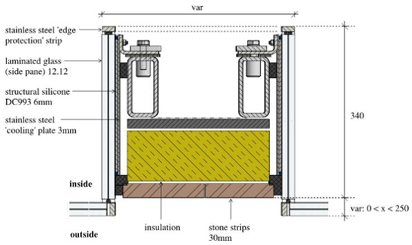
2.5.Thermal analysis edge element
Glass fracture can occur on days with clear sky conditions but strong sun irradiation and high ambient air temperature amplitudes. The clear and non-shaded part of a glass pane is then heated up rather quickly, while shaded parts remain relatively cool. The warmer zone expands relative to the cooler zone causing tensile stress. If this stress is sufficiently high, this phenomenon can cause cracks in the glass. For annealed glass with smooth grounded or polished edges, maximum 24 MPa is allowed for thermal stress in the glass.
The starting point during the design was to have an anthracite pre-smearing on the annealed side panes that are partially inside and pre-smeared and partially outside and clear.This is different from the typical situation mentioned above that could lead to glass cracking. According to analyses of RBGT Roehner Bauphysik u. Glastechnikthe temperature difference between the dark (uncooled) pre-smeared part and the clear outside glass are maximal in the winter period: 52 degrees. This leads to a maximum thermal stress of almost 30 MPa, meaning heat strengthened glass was needed.
Since annealed glass was required due to manufacturing method and aesthetically desired, some changes were needed to decrease the maximum temperature difference between the clear outside and shaded inside glass. The risk of thermal breakage of the annealed side panes is reduced by gluing stainless steel plates to the glass elements that act as cooling ribs and changing the colour of pre-smearing to light grey. On some of the stainless steel plates two studs are welded for making the connection to the main structural steel. The maximum temperature difference was hereby decreased to 39 degrees causing a thermal stress of 22 MPa.
Amsterdam’s summer in 2019 was a hot one. When an air temperature around 40 degrees was measured, temperature measurements on the glass where carried out to compare calculations with reality. All measured values where within the calculations which gives some confidence for the rest of the year relating to the risk on thermal breakage.
2.6.Custom-made doors
The façade contains two oversized structurally bonded doors made of laminated heat-strengthened glass with structurally bonded stainless steel framing. They are integrated into the main frame of stainless steel elements that support the glass façade. The glass box on the right has fixed glass elements but with a similar geometry as the doors. The glass box in the middle has the same stainless steel sections bonded to the static glass elements, but also features an extra stainless steel door frame with structurally bonded door. The glass box at the left features a smaller door to provide space for the door hardware to accommodate the facilities of the top floor apartment, such as an intercom and mail box.
To meet the building regulation, the curves of the façade were optimized for the required minimum free width and height to enter the store and apartment. The shop door measures 2.9 m high and 1.5 m width in closed position.
As minimalistic detailing was pursued by the design team, the door frame and all its hardware was integrated into the load-bearing stainless steel frame. Also, the top pivot is hidden in the 25 mm thick horizontal plate which is connected through a glass joint of 10 mm to the main steel. All structural stainless steel elements were produced within a tolerance of 2 mm so the door can open and close smoothly. All the stainless steel parts have a very fine grade finish without a shining look. To reach a high level of visual quality using structural bonded connections, all joints were pre-smeared with an overlap to contain a visual smooth line of silicone.
An important part of the hardware design is the custom-made door handle on both door leaves. The door handle is curved and varies in section size from start to end in fluent lines. It is custom-designed and produced for this project.

2.7. Replacement strategy
From the start of the project the design team frequently discussed the replacement of the complex curved glass elements. Although some glass panels are more prone to breakage than others, each glass pane needs to have an option to be replaced without causing severe damage to other glass panes or the interior of the shop. As SGP laminated annealed or heat-strengthened glass is applied there is no danger in case of glass pane breakage. Even with both panes broken it is expected the glass will stay in its place.
The main philosophy of the replacement strategy is to remove as little glass panes as possible when replacing a laminated glass element. It is hard to create a similar quality of the factory-applied bond on site so conditions on site will be closely monitored. Replacement will need to be done in a short amount of time in the famous shopping street in Amsterdam. Therefore, all unique glass panes are already in stock and stored close to the project location. The replacement strategy is developed and all steps for replacement are written down in an operational and maintenance manual to inform future owners and their engineers, and contractors.
Since the glass is annealed and has a complex shape with a long lead time, special attention during replacement is needed. The replacement of the glass panes is a complicated job. In some cases, a connected pane needs to be temporarily supported while another is replaced. To place a new one, temporary tools made out of POM are already designed to keep the glass and stainless steel at the right place for gluing on site.
Side glass panes (number 5, 4, 9, 13in figure 3) will be replaced from inside with hoisting tools. These panes need to be disconnected from the front pane and the structural main steel by cutting off the silicone joint, and from the structural main steel..Then the pane needs to be taken out from inside and replaced. One of the complicating factors is the masonry string course at the first floor levels that continues inside the glass boxes. This is designed as one relatively light-weight component per glass box so it can be easily removed easily while replacing a side panel.
Before placing a new glass side panel, it needs to be pre-smeared with silicone in light grey (surface) and black (edges) in the factory. Also, stainless steel cooling ribs will be applied before transportation to site, so on-site gluing is minimized to the (well accessible) joint with the front panels. For the replacement of side panes the top stainless steel insulated roof is designed in such a way that it can be partially removed to create an opening. Via this opening, a side pane can be hoisted out and in.
Glass panes at the front (1, 3, 7, 8, 10, 14, 15in figure 3) will be replaced with the help of a glass sucker from the outside. They are the heaviest glass elements with a weight of 260 kg. After attaching the sucker to the broken front pane the silicone joints glued to the side panels will be cut and temporary supports are applied. The edges of the new laminated glass elements also need to be pre-smeared with structural silicone in black beforehand in the workshop. When placing the new front panels structural silicone in the side connections is applied on site and the bottom injection mortar joint is created again.
3. Prefabrication and installation
3.1. Pre-assembly
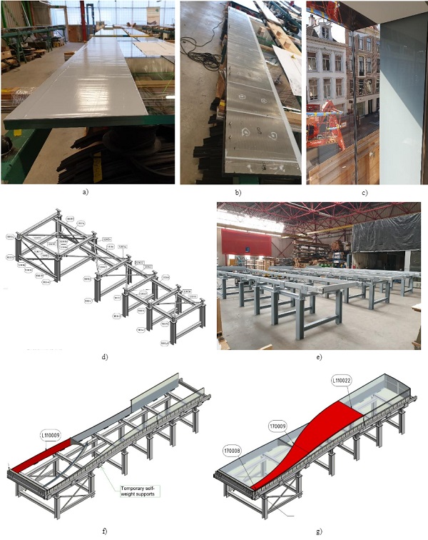
Due to the minimalistic detailing, desired quality and geometrically complex glass shapes, it was decided to pre-assemble all three glass boxes in the workshop of Octatube. By doing this, all glued details were applied under well-monitored conditions in the factory.
Since each glass box has a width of 1.8 m and height of 8.2 m, it was no option to pre-assemble the glass units vertically: the glass boxes were therefore pre-assembled horizontally and needed to be rotated 90 degrees on site. This resulted in extra analyses of stiffness of dead load supports.
The glass boxes are assembled in the following steps (see figure 14):
a) Pre-glue the side fins with light grey structural silicone, first 1 mm, then 5 mm and then glue stainless steel plates to the glass.
b) Pre-smear all glass edges with DC993 black structural sealant.
c) Glue the stainless steel end strip to the fins.
d) Assemble the supporting structure below the glass box.
e) Place structural main steel rectangular hollow sections in the supporting structure.
f) Place all glass side panes (fins) and use temporary supports to the main steel structure to carry self-weight.
g) Place stainless steel portal frame (around the door opening).
h) Place all front panels and the stainless steel roof.
i) Place stainless steel elements at intersections of front and side panels.
j) Inject critical details which support self-weight of the glass units.
k) Glue all connections between stainless steel and glass.
The two doors were separately produced and brought to site in a later stadium.
The first step needs craftmanship to prevent colour differences in the surface gluing. World-wide recognized experts were brought in to create these important connections. The result is stunning: the surface looks like a printed frit on the glass.
While in horizontal position, some extra L-shaped profiles are added to the main steel structure. These transfer the permanent load due to the weight of the glass and secondary steel to the RHS sections. Since in horizontal position, this weight needs to be carried otherwise by the full surface glued joint. To minimize long term stresses on this joint the temporary L-shaped profiles are introducedas can be seen in figure 14.
In all steps, tolerances play a big role. A lot of moulds were needed to produce the stainless steelel ements. Some stainless steelel ements are curved in one direction and later bended in the other direction, meaning a double curved shape in the end. The glass is also curved and all this needs to be joined with minimal tolerances in the corner detail. The making of these glass boxes was compared to making a Swiss watch, but then in the building industry.
Alot of temporary elements made out of POM were made to keep the glass and stainless steel in the right place and at the correct distance for structural gluing. All structural joints were glued in multiple steps: first create a structural connection at a recessed location, then remove the temporary POM elements and glue the visible part of the joint in one go.
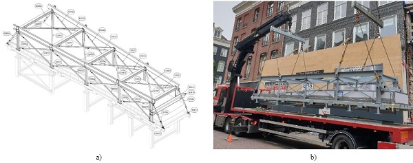
3.2.Transportation and installation
A special assembly steel structure was designed for both transportation and rotationon site. The assembly frame was mechanically coupled to the main steel ‘picture frame’ of the glass boxes. The assembly structure surrounds the glass boxes on all sides and creates a stiff structure around the glass boxes. This stiff frame prevented the glass box to move and rotate freely while transporting or rotating on site.
After completion of the glass boxes, (approximately 4 months from the start of production of the main steel to completion for transport), all boxes were carefully packed with a white plastic plate of 7 mm with air ducts. This protects the glass boxes not only during transportation and the rotation on site, but also in a later stage, when the masonry was applied.
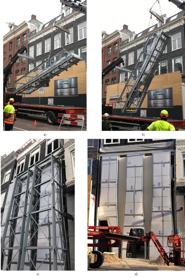
The rotation of the glass boxes from horizontal to vertical only took a few minutes. For every box the total installation time including rotation, lifting and connecting to the main structure was just 1 hour. Due to the quick assembly all three steel and glass boxes were installed in 2 days.
The rotation was done with two cranes at the same time with an elaborate pully mechanism at the top and bottom of each glass box. In the beginning the glass box is carried by both pully mechanisms, while in the vertical end position only one crane plus pully mechanism carries the load.
Brackets attached to the main steel structure were already pre-installed and positioned before arrival of trucks. After connecting the boxes to these brackets the assembly structure was totally removed, while the plastic protection around the glass boxes stayed in place. This protection was released after the completion of the masonry to prevent breakage or scratches on the glass.
4. Conclusion
Present day facades feature more and more curved glass projects with increasing element sizes. Those projects show that the glass industry is developing in a very visible way. The Looking Glass façade is much more subtle and can easily be overlooked by the untrained eye. It is relatively small in scale and blends with the adjacent building architecture. It is however unique with its curved geometry, minimalistic detailing and high-quality materials. A wide range of specialists came together to realize the client's ambition and architectural dream. A hybrid glass structure was created, while construction and assembly were embedded in the design from early stage, to enable a seamless installation.
5. Discussion
The quest for minimal detailing led to the design choice of laminated non-insulated glass. This is common for shopping windows, however one should strive to minimize required operational energy. It also led to structurally bonded details which will require regular maintenance regime. The design team discussed all this in detail and made sure to mitigate risks to be as low as possible. A rigorous maintenance regime and condition assessments will be the challenge for the near future - just as with any other innovative designs.
6. Acknowledgements
Client Warenar Real Estate for the ambition; architects from UN Studio for frequent collaboration; photographs by EvaBloem; coordination architect Gietermans & Van Dijk –Architecten, Arup Netherlands and UK façade and fire engineers as well as project management team; Invest in Arup internal fund - Hybrid Glass Structures which was key hub to share ideas and discuss future of glass designs; Octatube design and assembly team; Veratio for stainless steel; Cricursa for curved glass master pieces.
7.References
- Bijster, J., Noteboom, C., Eekhout, M.: Glass Entrance Van Gogh Museum Amsterdam, Glass Struct. Eng.1: 205–231(2016). DOI 10.1007/s40940-016-0022-5
- Dow Corning: Proven performance that lasts. http://dow.com (2019). Accessed 04 February 2019
- Descamps, P.,Hayez, V., Chabih, M.: Next generation calculation method for structural silicone joint dimensioning, Glass Struct. Eng.2: 169–182(2017). DOI 10.1007/s40940-017-0044-7
- Dias, V., Odenbreit, C., Hechler, O., Scholzen, F., Zineb, T.B.: Development of a constitutive hyper elastic material law for numerical simulations of adhesive steel-glass connections using structural silicone, Int. J. Adhes. Adhes. 48, pp. 194-209(2014)
- Lenk, P., Noteboom, C., Arkinstall, M.: Hybrid Glass Structures – Design Philosophy and Selected Checking Procedures. Challenging Glass 6 (2018)
- Staudt, Y., Odenbreit, C., Schneider,J.: Failure behaviour of silicone adhesive in bonded connections with simple geometry, Int. J. Adhes. Adhes. Volume 82, Pages 126-138 (2018)