This paper was first presented at GPD 2019 by Vaughn Schauss from Kuraray America, Inc..
Glass has become a popular material for use in balustrades, guards, and railings. Historically, monolithic tempered glass has been primarily used in North America, but with the recent changes to the International Building Code (IBC 2015), laminates with heat strengthened or tempered glass are now required. One growing application is cantilevered balustrades, where the glass is only secured at the bottom in a base shoe leaving the other three sides without support. In the past with monolithic tempered glass, cement based grout was used to secure the glass into the base shoe.
With laminated glass, cement based grouts have been known to lead to delaminations and breakage. As the use of laminated glass continues to increase in cantilevered balustrades applications, new materials for securing the glass in the baseshoe have been developed such as dry glaze systems and non-cement containing grouts. With these new installation techniques and materials, questions have arisen over how to properly define the support conditions when using finite element analysis software such as SJ Mepla.
To answer these questions, testing was conducted on laminates made with standard PVB, stiff PVB, and ionoplast interlayers. The laminates were tested under linear and concentrated loads while measuring their deflection. The deflection and stress of the laminates were also determined via FEM analysis using sandwich and effective thickness approaches with the different support conditions available in the software programs. In addition, the glass stress and deflection were also calculated using the cantilevered beam with linear load formula found in ASTM E1300 appendix X9. The results from the various calculation methods were then compared to the tested values.
1 Introduction
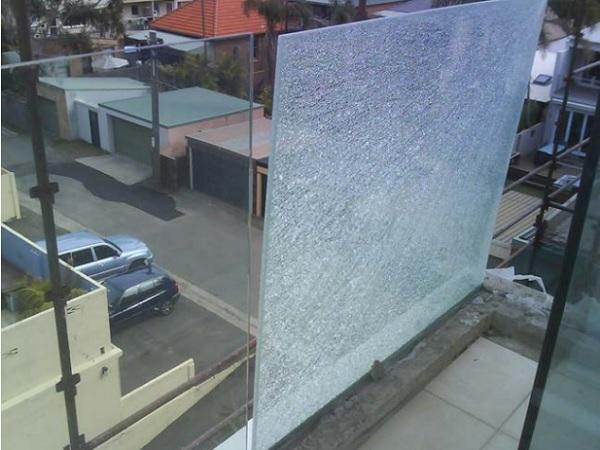
From breathtaking ocean views, to unobstructed visibility of stores in malls, glass has become a popular material for balustrades. Whether as in-fill panels or glazing systems that are two- or three-side supported, point supported, or cantilevered, glass provides high vision while still functioning as a safety barrier. Monolithic tempered glass has predominately been used in the past, but recent news headlines of falling glass have fueled the building codes to require laminated safety glass in most cases.
Once broken, monolithic tempered glass does not provide post breakage strength or safety for the occupants; however, laminated glass, made with an interlayer sandwiched between two lites of glass, can provide post breakage strength and continue to protect the opening even after breakage. In addition to the building codes now requiring laminated glass, the new 2018 International Building Code (IBC) allows the top rail or handrail to be removed from structural laminated glass balustrades if the laminate remains in place after breakage when tested according to ASTM E2353.
With the changes to the building codes, questions have arisen about how to model laminated glass for balustrade applications, especially for cantilevered balustrades. To answer this question, a test program was set up to compare physical test results to finite element analysis (FEA) software and the formula in ASTM E1300. The laminates, supported only at the bottom in both a wet glazed and dry glazed base shoes, were subjected to a linear load, a concentrated load, and the pendulum impacts according to ASTM E2353.
2 Code Changes
2012 IBC
Under the 2012 IBC, glass balustrades were allowed to be monolithic tempered glass with a minimum thickness of 6mm, as long as they met the requirements for safety glass [1]. To be considered safety glass, the monolithic tempered glass has to comply with the requirements for Category II of CPSC 16 CFR 1201 or Class A for ANSI Z97.1. For tempered glass, this means that the glass is impacted with a 45 kg leather bag dropped from a height of 1,219mm.
To comply, the glass cannot break, or if it does break, the ten largest pieces cannot weigh more than the equivalent weight of ten square inches of the original specimen. In addition to classifying as safety glass, the glass must also withstand the required wind load, as well as a 0.89 kN concentrated load, and a linear load of 0.73 kN/m, with a safety factor of four used for the concentrated and linear loads.
The safety factor of four is intended to be used to reduce a material’s ultimate stress to allowable stress in design calculations, not to increase the applied loads. For instance, tempered glass has an ultimate stress of 165 N/mm². Applying the safety factor of four will result in an allowable stress of 41.36 N/mm².
Although laminated glass with tempered or heat-strengthened glass has always been allowed by code, monolithic tempered glass was typically used prior to the 2015 code change. It should be noted that the 2009 IBC did require laminated glass for railings in windborne debris areas and for systems that did not contain a top cap as part of the system design.
In 2011, there were several news reports of monolithic tempered glass falling multiple stories to the pedestrian sidewalks below. In Toronto, Canada, there were 30 reports between 2010 and 2011 of glass falling from 11 buildings [2].
This scenario was not localized to Toronto. Other cities like Austin, Houston, Seattle, New York City, and Chicago experienced glass falling from balconies. Many investigations were performed and nickelsulfide inclusions were at the top of the list of causes; however, other contributors were product design and installation issues. With all the negative press, the glass industry looked to the future and began to propose a change to the codes.
2015 IBC
The 2015 IBC took a large step forward to prevent glass fallout. Section 2407 was revised to require laminated glass in all balustrade applications. The new code eliminated the use of monolithic tempered glass, but did include an exception. Monolithic tempered glass could be used if there was no walking surface below the railing or the walking surface was protected from falling glass [3]. Laminated glass must still be classified as safety glass and impacted with the leather bag.
However, for laminated glass to pass the impact test, it either cannot break, or if it does, it cannot have any tears or openings through which a 76mm sphere can be passed with an applied force of 18 N. Unlike monolithic tempered glass, which is allowed to vacate the opening, laminated safety glass must continue to remain in place and not allow any opening larger than 76mm. The other load requirements remained the same as in the 2009 version, including the approval by the building official to remove the top rail.
2018 IBC and ASTM E2353
For the 2018 edition of the IBC [4], the only change was the removal of the building official’s approval to remove the top rail. Under the new code, it is now possible to remove the top rail if it is laminated safety glass with two or more lites of equal thickness and the glazing is tested to remain in place as a barrier when impacted or broken according to ASTM E2353 Standard Test Methods for Performance of Glazing in Permanent Railing Systems, Guards, and Balustrades [5].
This standard outlines how to test balustrades for static strength, impact performance, and postbreakage characteristics. After subjecting the glass to the static loads (uniform, linear, and concentrated loads), the glass is impacted using the same apparatus and impactor as ANSI Z97.1 [6]. The glass is then impacted again with a different pendulum apparatus equipped with a metal nose impactor specified in ASTM E2025, a standard that was withdrawn in 2015 [7].
After the impact, the glass is classified into four categories: (1) glazing is unbroken, (2) glazing is broken but still retained in the opening and no passage of the solid sphere, (3) glazing is broken and shards contained but the ball passes through, and (4) the glazing is broken and shards are not contained. In addition, ASTM E2353 also classifies the different types of railings, guards, and balustrades based on the glazing support. There are six glazing types, and a cantilevered balustrade supported only at the bottom in a base shoe is type V. Type V and VI require the impact to be within 50 mm of the center and no more than 200 mm from the top.
3 Test Program
To understand how FEA modeling and ASTM E1300’s formula compare to actual testing, a test program was initiated that would measure the deflection under linear and concentrated loads followed by impact and post-breakage concentrated load. Twelve laminates were prepared using two lites of 8 mm tempered glass. The laminates were 1,067 mm long and 1,067 mm tall. Three different interlayers were chosen, polyvinyl butyral (PVB), stiff PVB, and ionoplast.
All the samples were installed in an aluminum base shoe from C. R. Laurence Co. Each base shoe measured 1,067 mm long and 120.6 mm tall with a channel depth of 101.6 mm by 38.1 mm wide. Three laminates, one of each interlayer, were wet glazed using Sika’s SikaGlaze GG-735 polyurethane (PU) grout. The two-part PU grout was mixed per the manufacturer’s instructions. With the laminates secured in place, the PU grout was poured into the base shoe and allowed to cure for 36 hours before testing.
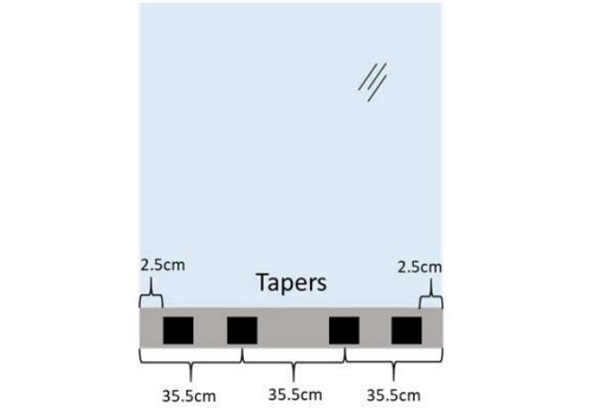
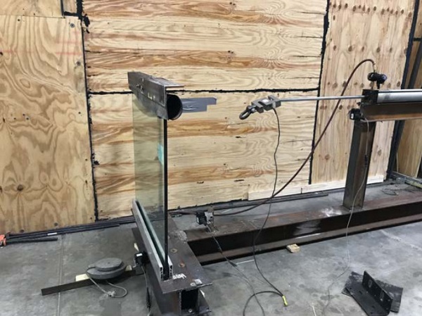
The remaining nine laminates, three of each interlayer, were installed using C.R. Laurence’s Taper-Loc dry glazed system. Four tapers were used per manufacture’s recommendation as shown in figure 1. The base shoe was installed on a steel I-beam that was bolted to a test frame and secured to the concrete floor with bolts as shown in figure 2 A pneumatic ram was used to perform the required load conditions.
Two metal brackets, one for the concentrated load and one for the linear load, were installed on the top of the glass. The linear load bracket measured 1,067 mm long by 38.1 mm wide, and weighed 24 kg. The concentrated load bracket measured 292 mm long by 38mm wide, and weighed 10 kg. A chain connected the brackets to a load cell attached on the end of the ram. A linear load of 0.73 kN/m was applied for 60 seconds while measuring the deflection with a linear transducer.
For the concentrated load, 1.33 kN was applied at top center for 60 seconds while measuring the deflection. After the static loads, the balustrades were impacted using the shot bag impactor described in ASTM E2353 dropped from a height of 1220 mm. If the laminates did not break upon impact, the steel (hard body) impactor was used. The samples were impacted in the center within 200mm from the top edge.
4 Modeling
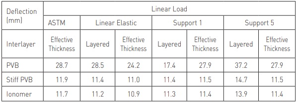
Two different methods were chosen to model the deflection of the laminate under load, FEA using SJ Mepla software and ASTM E1300 cantilevered balustrade equation found in appendix X9 [8]. Both methods used the minimum glass thickness and the interlayer’s shear modulus at 20°C and 1 minute. According to ASTM E1300, the minimum glass thickness for 8 mm glass is 7.42 mm. The shear modulus at 20°C and 1 minute was 1.2 N/mm2 for PVB, 120 N/mm² for stiff PVB, and 192 N/mm² for Ionoplast.
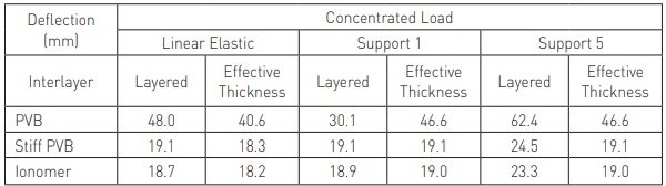
To model the support conditions in SJ Mepla, there are a few different options; however, type 1 and type 5 were selected. Type one simulates the degrees of freedom w, u, v, φ, and θ equal to zero, while type 5 only w, φ, and θ are equal to zero. In addition to these two support conditions, modeling was also performed with elastic line supports. Five linear elastic supports were used that spanned the entire laminate length and were 20mm wide. The E modulus was 30 N/mm2 with a height of 5mm. The modeled deflection values are in tables 1 and 2.
5 Results
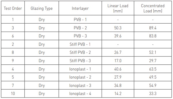
The testing proved to be quite difficult. Two of the samples broke prior to testing, and the polyurethane grout-mixing machine for the wet glazed samples broke. As a result, only results for the dry-glazed samples were available at the time of publication. In addition to these challenges, an issue with the stability of the base shoe also occurred. The design of the mounting system allowed the base shoe to roll, and resulted in larger than expected deflections.
To reduce the roll, a gusset was welded to the I-beam that held the base shoe. This added some additional stability, but excess deflection was still detected. Additional bolts were added to secure the assembly to the concrete floor, as well as tightening every bolt prior to testing. Because of these issues, the deflection is not consistent as noted in table 3; however, the last few samples tested did see reduced deflections.
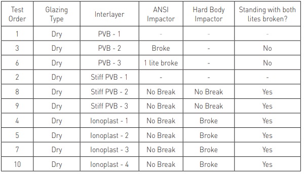
Table 4 shows the results from the impact testing. The first impactor was the soft body impact followed by the hard body steel impactor. If the glass did not break from the impactor, it was manually broken with a hammer. Once broken, the PVB laminates fell over, while the Stiff PVB and Ionoplast laminates remained standing upright. After one minute of standing, the 10 kg concentrated load bracket was placed back on the top of the now broken glass laminate and a load was applied until the laminate fell over. Stiff PVB withstood a load of 285 N before failure, while Ionoplast withstood 489 N. All of the testing was performed at a controlled temperature between 20°C and 21°C.
6 Conclusion
The intent of this test program was to compare physical testing of cantilevered glass balustrades to common engineering calculations such as finite element analysis and the balustrade equation from appendix X9 in ASTM E1300. The samples were subjected to a concentrated and a linear load, as well as impact testing according ASTM E2358. Based on these results, only laminates with Ionoplast and Stiff PVB interlayers fulfill the requirements for cantilevered glass balustrades according to the 2018 IBC.
During the physical testing, issues with the installation of the base shoe allowed for larger than expected deflections. To correct this, a gusset was added to the I-beam to prevent the base shoe from rolling. This resulted in reduced deflections of the glass. Based on this experience, the installation of the base shoe plays an important role in the performance of the laminate.
Mounting the base shoe directly to a concrete base would probably have produced better results. Although the original plan was to test both the dry glazed Taper-Loc system by CRL and wet glazed with Sika’s SikaGlaze GG735, there was an issue with the pump for the wet glazing. As a result, only data for the dry glazed system is available at the time of publishing. Future testing of the wet glazed system is needed.
The different calculation approaches produced some interesting results. For the linear and concentrated loads, the layered results for the linear elastic and support condition 1 were very similar, while support condition 5 was a little higher. This was only true for Ionoplast and Stiff PVB. The values for standard PVB varied greatly. When using the effective thickness method, the different support conditions were similar for each interlayer, although the linear elastic values were slightly lower.
The ASTM E1300 effective thickness balustrade equation for a linear load also produced very similar deflection values to FEA using the layered or effective thickness approach, at least for the stiffer Ionoplast and Stiff PVB interlayers. With standard PVB, the E1300 equation was similar to the layered linear elastic support and the effective thickness method with support 1 and 5.
Because there were some issues with the tested deflection data, further testing is required with better support conditions to compare with the calculated values. However, the last few samples tested were closer to the calculated ones. With all of the testing and modeling performed at 20°C and a 1:1 size ratio, these findings may not hold true at higher temperatures or different sizes. Therefore, further testing is needed to determine the effect of higher temperatures as well as different dimensions.
References
1. International Code Council. (2012). 2012 – International Building Code. Retrieved from https://codes.iccsafe.org/content/IBC2012?site_type=public
2. Ontario Ministry of Municipal Affairs and Housing. (2012). Expert Panel on Glass Panels in Balcony Guards Report – 2012. Retrieved from http://www.mah.gov.on.ca/Page9948.aspx
3. International Code Council. (2015). 2015 – International Building Code. Retrieved from https://codes.iccsafe.org/content/IBC2015/toc
4. International Code Council. (2018). 2018 – International Building Code. Retrieved from https://codes.iccsafe.org/content/IBC2018?site_type=public
5. ASTM E2353-16, Standard Test Methods for Performance of Glazing in Permanent Railing Systems, Guards, and Balustrades, ASTM International, West Conshohocken, PA, 2016, www.astm.org
6. From ANSI Z97.1-2015, “For Safety Glazing Materials Used in Buildings – Safety Performance Specifications and Methods of Test”, copyright Accredited Standards Committee (ASC) Z97; 800 SW Jackson St Suite 1500, Topeka, KS 66612 – 1200. A copy of the complete standard may be obtained from www.ansiz97.com.
7. ASTM E2025-99(2006), Standard Test Method for Evaluating Fenestration Components and Assemblies for Resistance to Impact Energies (Withdrawn 2015), ASTM International, West Conshohocken, PA, 2006, www.astm.org
8. ASTM E1300-16, Standard Practice for Determining Load Resistance of Glass in Buildings, ASTM International, West Conshohocken, PA, 2016, www.astm.org