Michael Elstner, state certified Engineer & Master Glazier
Head of the INTERPANE Consultancy Service (IBC)
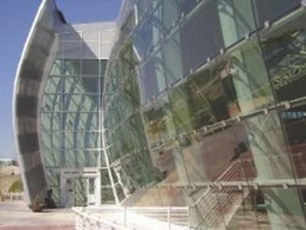
Glass is the dominant building material in modern architecture. It creates visual accents and offers multiple technical features like glass for thermal insulation, solar protection, and sound proofing, as well as a design component, safety glass, or as a part of solar plants. The industry nowadays offers glass with customised technical data for every application possible.
In architecture, a special emphasis is often placed on energy-saving building methods, particularly in view of the rising energy and raw material costs which are the greatest challenge of our times. Due to the wide diversification of the technical features, tailor-made technical glass consulting is becoming an increasingly important service in architectural glazing. This paper describes the historical context as well as the evolution of glass as a material and its applications in windows and facades, with a description of its most important building-physics values.
The history of glass
Flat glass has been used for around 2000 years as a space-enclosing component and is, therefore, one of the oldest artificial building materials. Due to ongoing developments concerning manufacturing and finishing methods, it is now also one of the most advanced building materials and it characterises modern architecture today.
Since it can now fulfil nearly any requirement of modern building envelopes, the conflict between the fundamental human need for protection from the outside world, on the one hand, and the openness to light, on the other hand, has now been overcome.
Flat glass was produced using casting, crowning or cylinder techniques until industrialization. These handcrafted methods were eventually superseded by sheet glass and polished plate glass production methods that were applied until the 1960s.
The disadvantage of the machine glass processes was that the glass was distorted and uneven. The grinding and polishing steps that were necessary for the production of high-quality plate glass were a cost driver. Both methods were improved over the years, but it was impossible to eliminate the fundamental disadvantages. In order to cover the increasing demand for high-quality flat glass, new methods were required.
At the beginning of the 1950s, the English company Pilkington Brothers invented an industrial solution and enabled high volume production of large plate formats, along with a consistently high quality at a relatively low price: This is known as the automatic float process and as a result, glass became a mass produced product that anybody could afford. As a result of the oil crisis in the 1970’s, the criticism of glass architecture increased. Uncoated flat glass at this time was a waste of energy. An ecological and economical milestone for higher energy efficiency was the production of thermal insulating and solar control coatings using thin-film technology.
Why is a coating applied?
Single glazing, which was standard until the middle of the 1970, is responsible for large thermal losses (Ug Ø ≈ 5.8 W/m2 K). Double glazing then became more common, with its improved Ug value of about 3.0 W/m²K. It was not until double glazing technology was combined with modern thin film technology to create transparent coatings on glass that the specific energy losses could be halved yet again. In contrast to metals, which re-radiate about 2 to 10 percent of the absorbed energy, i.e. which have a low emissivity value, ε, glass does not possess this favourable property.
More than 80 percent of absorbed heat is emitted via the glass surface (ε ≈ 0.85). In order to combine the transparency of glass with the excellent emission properties of precious metals, thin metal films are deposited onto the glass. These are transparent to sunlight but simultaneously reduce the emissivity of the glass surface very effectively. Extremely thin silver films with a thickness of about 1/100,000 mm (= 10 nm) are optimal.
Colour-neutral, coated insulating glazing was first introduced by INTERPANE to the market at the beginning of the 1980. A vigorous market campaign, including the distribution of basic coated glass as a semi-finished product, ensured that iplus was soon widely disseminated. Today, thermally insulating glazing (low-e glazing) with a Ug value of ø 1.1 W/m²K is accepted as the state of the art. With triple glazing, Ug values down to even 0.5 W/m²K can be achieved. This means thermal losses that are only a tenth of those for single glazing!
The Structure of low- emissivity and solar control coatings
Different coating materials are deposited onto glass to produce functional coatings. These provide adhesion, thermal functions, cover and protection, forming a complex system. The optical properties are achieved by applying the interference principle, which is familiar from antireflective coatings on camera and spectacle lenses.
The ipasol solar-control coatings are similar to the others in principle, but have a significantly more complex coating structure. The desired properties regarding solar and thermal radiation are obtained with additional absorbing and/or reflecting components

Fig 1: Example: Structure of a simple Low- E coating on glass
Coating technique
At INTERPANE, in-line sputtering in vacuum chambers is used as the coating technology (Fig. 2). The pressure in the sputtering chamber is reduced to about one millionth bar (app. 10-3 mbar). The glass pane is transported from the input chamber through a transfer chamber to the sputtering chamber, where the coating process actually takes place. In order to obtain homogeneous coatings, the glass is transported under the coating devices at a constant speed.

Fig. 2: Schematic diagram of the continuous operating coating line with high-performance sputtering (in-line method).

Fig. 3: Schematic cross- section of a cathode chamber to deposite thin films by the magnetron sputtering procedure

Fig. 4: Surface processes during sputtering
The coating procedure itself is shown schematically in Fig. 3: For sputtering, plasma is created in a vacuum chamber by applying a high voltage between a cathode and an anode. The plasma forms when atoms of the inert gas, argon, are introduced into the chamber and are transformed into heavy, positively charged argon ions by collisions with electrons. The plasma can be recognised by its typical coloured appearance, similar to that in fluorescent tubes.
The strong electric field created by the high voltage accelerates the heavy, positively charged argon ions toward the cathode. A so called "target", which consists of the coating material (e.g. silver), is mounted on the cathode. The incident high-energy argon ions knock material out of the target, which is then deposited as a thin layer on the glass (Fig. 4). Oxygen may be additionally introduced into the chamber as a reactive gas to form chemical compounds with the atomised target materials.
Important building-physics values
Ug-value according to EN 673
Heat transmittance through a surface by conduction, convection and radiation is expressed by its U value according to European Standards. This was formlerly known as the K coefficient in some contries. The thermal transmittance (U value) specifies the heat flow per unit time through 1 m2 of a building component for a temperature difference between the adjoining room and the outdoor air of 1 Kelvin.
Thus, the lower the U value, the better is the thermal insulation. The units for specifying a U value are W/m²K. The Ug value is determined by calculation according to EN 673 or by measurement according to EN 674. Under the same boundary conditions, the calculation and measurement procedures result in comparable U values. The ASHRAE/NFRC yield a slightly worse (higher) U value than the European standards (approx. 0.1-0.2 W/m2K). The ASHRAE/NFRC U Value is separated into winter and summer conditions.
Emissivity ε according to EN 673
The emissivity value, ε, describes the radiative property of the surface of a body. With respect to the thermal insulation of insulating glazing, the lower the emissivity value, the better is the U value. In the past, the U values of glazing were always measured in a test rig – today, reliable calculation procedures are available (EN 673). One of the values needed for the calculations is the ε value.
The emissivity value is determined by measuring the infrared reflectance of a building component surface. It is assumed that the angle of incidence is almost perpendicular to the considered surface and that radiation of different wavelengths is used for the measurement. The reflectance value R determined in this way is converted into the emissivity value using the formula
ε = 1 – R
As it is not possible, from a metrological point of view, to measure with an angle of incidence of 0°, measurements are generally made with an average angle of incidence of ≤ 10°.
Normal emissivity εn according to EN 673
The determination of the normal emissivity value εn according to EN 673 is based on the measurement procedure described above, where 30 wavelengths between 5.5 µm and 50 µm are evaluated. The mean value is determined from these individual results, with the spectral distribution of thermal radiation at + 10 °C being taken into account. The result is designated the “normal emissivity value εn”.
Declared emissivity εd according to EN 1096
The declared value of the emissivity, εd, is the nominal value of the normal emissivity specified by the manufacturer of the basic glass.
The solar factor (SF) or g-value according to EN 410
The solar factor is the total energy transmittance (or solar heat gain coefficient) of glazing for solar radiation in the wavelength range between 300 nm and 2500 nm. The solar factor is significant for HVAC calculations (heating, ventilation, air-conditioning) and is expressed in %. The solar factor is the sum of the direct solar energy transmittance τe and the secondary internal heat transfer factor qi describing long-wave radiation and convection.
g = τe + qi
b-factor or shading coefficient (SC)
The “average transmittance factor b” (also called the shading coefficient SC) is the decisive factor for calculating the cooling load. The b-factor is the ratio of the solar factor of the evaluated glazing unit to the solar factor of a conventional double-glazed window, according to German VDI 2078 (edition July 1996).
![]()
Internationally (USA- ASHRAE, NFRC or UK- CIBSE) the shading coefficient is the ratio of the solar factor of the evaluated glazing unit to the solar factor of a 3 mm single glazing.

In some contries the shading coefficient is separated into long-wave and short-wave components, whose values are derived in exactly the same way, by comparing with the same property of a 3 mm clear float. The short wavelength shading coefficient (SWSC) is the direct solar energy transmittance e divided by 0.87. The long wavelength shading coefficient (LWSC) is the secondary internal heat transfer factor qi, again
τe divided by 0.87. Both together give the same result as described above. Drawing international comparisions it is more common to determine the SC by dividing the solar factor by 0.87.
Colour rendering index Ra according to EN 410
Colour rendering is very important for physiological perception and for psychological and aesthetic reasons. The colour effect in a room is influenced by the spectral distribution of the incident daylight. The maximum value that can be taken on by the general colour rendering index Ra is 100. This value of 100 is attained in glazing-types where the degree of spectral transmission within the visible spectral range is absolutely constant (e.g. ipawhite: Ra,D 100 up to a glass-thickness of 8 mm uncoated).
In terms of lighting technology, general colour rendering index-values of Ra > 90 indicate a very good level of colour rendering, and index-values of Ra > 80 indicate a good level thereof. The Ra,D-value describes colour recognition by daylight firstly within the room and secondly outdoors, as viewed from indoors through the window. In a comparable way, the Ra,R-value characterizes the colour rendering of the glazing for outdoor reflections. The colour rendering characteristics of glazing are established by means of the general colour rendering index Ra in accordance with EN 410. Used as the basic reference illuminant is the normal illuminant D 65.
Light transmittance τV according to EN 410
The light transmittance τV is the ratio of the visible light (380 to 780 nm) that is transmitted through glazing, weighted by the sensitivity of the human eye. The light transmittance is indicated as a percentage and can be influenced by the glass thickness, for example. Due to the varying iron oxide content of the glass, slight fluctuations are possible. A single-pane of clear float glass has a light transmittance of approximately 90% in the spectral range of the visible light (the 10% loss being mainly due to reflection).
An INTERPANE insulating glass consisiting of two float glass panes, has a light transmittance of 82%. iplus neutral E has a light transmittance of 80%. The reference value of 100% corresponds to a wall opening without any glazing. The light transmittance of the glazing should be selected appropriately for the building and the environment.
Energy absorption αe according EN 410
In addition to transmission and reflection, absorption is the third process determining radiation transport through glass. Radiated energy is converted by absorption into thermal energy. This causes the temperature of the absorbing glass pane to increase. If the absorption is ≥ 50% for horizontal glazing and ≥ 55% for vertical glazing, INTERPANE recommends fully toughened or heat-strengthened glass. This recommendation is based on a typical location without any static/severe shadow on the glazing. For specific applications, however, an analysis of thermal glass breakage risk is recommended. The Interpane Consultancy Service (IBC) would be pleased to assist you.
Transmission
+ Reflexion
+ Absorption
--------------------
= 100 %
Selectivity characteristic S
The selectivity index serves to indicate the ratio of the degree of light transmissivity τV to the degree of total energy transmittance g. A high selectivity index expresses a favourable ratio.

Thermal effect of insulating glass with a low-E coating
The heat flow through insulating glazing is determined by the following components:
- radiation exchange between the panes according to the emissivity of the pane surfaces for thermal radiation
- heat conduction by the gas in the gas-filled space
- convection of the gas in the gas-filled space

Fig. 5: Heat flow through insulating glass
In conventional, uncoated double glazing, about two-thirds of the heat flow is due to the radiation exchange between the panes due to the high emissivity of the glass surface. Only one third is caused by conduction and convection of the air in the space between the panes. The low emissivity coating reduces the emissivity from εd ≈ 0.89 for uncoated glass to, for example, εd ≈ 0.03 for iplus E. Thus, the radiation exchange is suppressed almost completely.
The heat flux due to conduction and convection in the gas-filled space remains unchanged. Thus, a low-emissivity coating based on silver, such as is used in iplus E, reduces the Ug value of double glazing from approximately 3.0 W/m²K to 1.4 W/m²K. If, in addition, the air in the space between the panes is replaced by an inert gas such as argon, which has a lower thermal conductivity, the Ug falls by a further 0.3 W/m²K to 1.1 W/m²K.
Outlook
The developments centred on the material glass are not merely restricted to classical features, such as energy-saving and solar protection, but also set out to improve and change its strength and look. Nature is often used as a model, such as in the case of the lotus effect, or those products that are offered that can control light and energy transmission flexibly and independently from the user.
Innovative solutions for decorative facade glazing are also very popular with the planners. In this context a new range of coatings is now available. So called “design coatings” such as ipachrome. This coating can be be applied partially or extensively and it opens creative opportunities for the design of buildings. The multi-layer system ensures that the glass is as reflective as a conventional silver mirror.
Since product diversity continues to grow, glass technical consulting for architects, planners, and clients in building projects is in high demand among glass processing companies. The INTERPANE Consultancy Service (IBC) in Plattling, which is located in Bavaria, Germany, assists national and international architects, engineers, planners, fabricators, and institutional building clients either by phone or on-site.
Apart from architectural and technical consulting for window and facade builders, the IBC also offers training courses and co-ordinates the national and international cooperation of architectural consultants and clients. The IBC can be reached via phone at +49 (0) 9931 950 229, fax +49 (0) 9931 950 236, or e-mail ibc@interpane.com.
8. References
[1]INTERPANE: Design with glass 7th Edition, 2007.
Michael Elstner, state certified Engineer & Master Glazier
Head of the INTERPANE Consultancy Service (IBC)
INTERPANE Glasgesellschaft mbH, Plattling, Germany
phone +49 172 85 14 519, michael.elstner@interpane.com

