Source: Glass Structures & Engineering
Author: Geralt Siebert
DOI: https://doi.org/10.1007/s40940-024-00286-9
Abstract
The German code for the design of glass structures, DIN 18008, was first published in its final version in 2010 and 2013; as several major changes were suggested, the periodical revision took longer than expected. Part 1 and 2 (basis of design and linear supported glazing) are published in final version in 2020, recently a draft of revised part 3 (point fixed glazing), part 4 (balustrade glazing) and part 5 (walk-on glazing) were published with date November 2023. Revision is based on experience from its practical application and implements recently finished research activities; it also takes development of other glass design codes including basis of future Eurocode Design of Glass Structures (CEN/TS 19100) into account. The paper shows the developments like reduced safety level for selected applications with lower consequence class (which is revolutionary for Germany), simplified calculation of conical point fixings, revised concept of classification and newly developed flow charts for design of balustrades. Overall, the field of application covered by the code is widened, more economic glass structures can be designed within the code. Calculation examples for IGU show difference of old and revised German standard for different applications to complete the picture.
1 Introduction
The use of glass elements has a long tradition, parallel to the application rules for design were developed. The concept of proper design was developed since mankind started to build structures: design and building always was (and still is) related to finding a good compromise between fulfilling safety requirements and meeting financial framework. After application of glass came more common one can see a shift of design by architects and engineers towards craftmanship, using developed knowledge and experience based “rules of thumb” for glass as a filling element of moderate size—and by this often regarded as “non-structural element”, a better classification would be element of low consequences in case of failure. Since several decades, with enlarged field of application and sizes, the shift from craftsmanship back to (structural) design architects and engineers can be recognized.
In the historical literature—insofar as publications (Schwering 1880, 1894) from the 1880s can be considered historical—the design of glass for iron-glass-roofs like used for upcoming railway stations or exhibition halls like crystal palace or other impressing structures is described by means of linear equations using corresponding material tests and assumed safety factors. In addition to design for static loads, the load case of hail impact and even accessibility for maintenance purposes is discussed. Strength limit values for different types of glass (e.g., blown glass, cast glass) and mechanical strength equations are aligned, i.e., both are similarly “wrong” due to the consistent use of linear equations; strength values depending on the glass thickness may have their origin in the non-linearity that is present to varying degrees.
As in Germany for most applications no code for glass design existed, the so-called “technical rules” TRXV (TRLV “Technical Rules for Linear supported Glazing” 2006, TRAV “Technical Rules for Anti-drop-device Glazing” 2003, TRPV “Technical Rules for Point supported Glazing” 2006) have been developed by a small group of experts under leadership of building authorities in the second half of 1990s. Experience from workmanship as well as from building praxis were transferred to technical rules. These followed the principle of global safety concept.
DIN standard working committee NA 005–09-25 AA was established in 2002 to develop a code according the concept of partial safety factors (DIN EN 1990: 2010 and DIN EN 1990: 2021, so called “Eurocode 0”). The German design code (DIN 18008 2010, 2013) is based on the revised final versions of (TRLV “Technical Rules for Linear supported Glazing” 2006), (TRAV “Technical Rules for Anti-drop-device Glazing” 2003), (TRPV “Technical Rules for Point supported Glazing” 2006) and (DIN 18516–4 1990). With this occasion, the field of applications covered by DIN 18008 was widened compared to TRXV.
On European level, WG8 of CEN/TC 129 (committee for product specifications) worked since decades on a code giving values for resistance of glass panels, finally published as (DIN EN 16612: 2019); practically this document is of no relevance in Germany. CEN/TC 250 SC11 is working on a Eurocode Design of Glass Structures since 2012, 2021 a basis for future draft version was published in form of (CEN/TS 19100: 2021).
A timeline and a more detailed overview about the design codes can be found in earlier published papers (Siebert 2016–2023), in the following only changes to actual regulations in power are of interest.
2 DIN 18008—field of application and general requirements
2.1 General
Based on multiple rules from the past and experience the code (DIN 18008-1, -2: 2010, DIN 18008–3, -4, -5: 2013) was set up and from January 2015 put to legislative power in Germany. Definition of terms and general basics are given in part 1, the rules for different applications are given in appropriate parts of the DIN standard. The structure of DIN 18008 is the following:
- Part 1: Terms and general basis
- Part 2: Linearly supported glazing
- Part 3: Point-fixed glazing
- Part 4: Additional requirements for barrier glazing
- Part 5: Additional requirements for walk-on glazing
- Part 6: Additional requirements for walk-on glazing in case of maintenance procedures and for fall-through glazing
After 5 years in service, the DIN working group reviews, if changes or a revision of a standard is necessary. Due to experience with application of the code and technological as well as scientific progress, the working group decided to revise and update DIN 18008. Work of DIN working group meanwhile is finished, part 1 and 2 was published in revised final version (DIN 18008–1, -2: 2020). For part 3, 4 and 5 a draft of revision was published in November 2023 (DIN 18008–3, -4, -5: 2023), discussions and objection meeting took place until spring 2024, so updated final versions can be expected by second half of 2024.
2.2 Design equation
In (DIN 18008–1: 2020) the principal design equation Ed ≤ Rd is given.
Ed for persistent and transient (fundamental) design situations follows Eurocode 0 (DIN EN 1990: 2021):
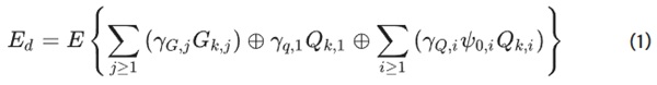
The only values not covered by Eurocode 0 are the values for load combination factors for combination of so-called IGU-related “climatic loads” (loading in cavity of IGU due to change of temperature, meteorological pressure or difference of production and installation height) Ψ0 = 0.6, Ψ1 = 0.5 and Ψ2 = 0 as defined in (DIN 18008–1: 2010 and 2020).
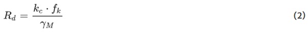
The design value of resistance Rd of thermal treated glass is given by quotient of material strength fk and material safety factor γM (for thermally treated glass γM = 1,5) multiplied by construction-factor kc (usually 1,0):
For calculation of design value of resistance of annealed float glass (fk = 45 MPa) an additional factor kmod for considering time dependence is introduced:
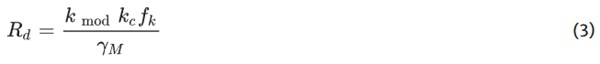
In the last equation the factor kmod = 0.7 for short term loading like wind or personnel load on balustrades, for mid-term loading like snow, temperature or change of meteorological pressure kmod = 0.40 whereas for long term loading (dead load or change in altitude) kmod = 0.25; in any case also the load combination without short-term loading has to be taken into consideration. That is to say only long-term loads like dead weight has to be taken into account—although this might not lead to a maximum value for stress the ratio of stress by resistance might become extreme. The safety factor for material float glass without tempering is γM = 1,8. The construction factor kc may be set to 1,8 for linear supported annealed float glass. In case of tensile stress along edges of float glass, resistance has to be reduced to 80%. The use of laminated safety glass is taken into account by a bonus of 10%, accounting for the probability of failure in a coupled system and not for the shear transfer.
2.3 Glass thickness and interlayer material—testing for residual strength
As upcoming photovoltaic elements often use reduced glass thickness down to 2 mm, combinations of non-symmetric glass setups and non-PVB interlayer materials get more common, several adjustments were made to accomplish for this. The minimum glass thickness covered by the updated version of design code (DIN 18008–1: 2020) is 2 mm—also CE-marking of such products might be a challenge if not included in a product standard. As the tolerances of thinner glass have a higher impact on design, a new partial safety factor for 2 mm glass is introduced: for annealed glass γM = 1,9 (instead 1,8) and for tempered glass γM = 1,6 (instead 1,5).
In DIN 18008 approved combinations for glass setup (thickness of glass and interlayer) often connected with size or span are given; these usually are based on experience collected with PVB-interlayer. To enable use of alternative interlayers, testing procedure to ensure sufficient residual strength (strength after breakage occurs) is defined for vertical and inclined installation in (DIN 18008–1: 2020) Annex B. It can be mentioned, that not all in DIN 18008 approved glass set-ups will fulfil the now fixed testing procedure—this is a compromise to allow new products with less existing experience and keep well experienced structures on the market.
2.4 Traffic safety
Probably no sentence has been discussed more and with more commitment than (DIN 18008–1: 2020) Sect. 5.1.4. After several changes the final wording of respective section reads:
If protective measures for glazing are required due to legal requirements for traffic safety, this can be fulfilled, for example, by restricting accessibility (barriers) or using glass with safe breakage behaviour.
A note to this requirement states, that it usually has to be applied. In practice, if one wants to avoid use of glass with safe breakage behaviour (which by the way is required by legislation of several neighbouring countries) one has to find an expert to take responsibility for this. In order to leave no room for discussion regarding the interpretation of “glass with safe breaking behaviour”, the following definition of “safe breaking behaviour” and precising note can be found in (DIN 18008–1: 2020) Sect. 3.1.3:
in the event of breakage, the fragments are held together and do not decompose or they break into a large number of small fragments.
Note: the fracture behaviour of glass is considered safe if it meets the standards for safety glass. Wired glass does not have safe breakage behaviour.
2.5 All-glass systems (“Ganzglasanlagen”)
Partition walls, door and vestibule systems as well as entrance areas can be summarized under the term “all-glass systems”. It would be conceivable to consider all-glass systems in DIN 18008. However, solutions that have proven themselves in building practice deviate from the current regulations in DIN 18008, which are designed for glass constructions of different dimensions and consequences in case of failure. In this respect, special, design-specific regulations would be conceivable here, based on a deviating (reduced) damage consequence. Since a differentiation of the damage consequences of glass in all-glass systems and, for example, in adjacent façades appears questionable, the idea of a design with reduced safety factors was ultimately not implemented.
Nevertheless, the new (DIN 18008–3: 2023) Annex F offers welcome support for construction practice through additional clarifications and, in particular, the possibility of waiving verification if design and application-specific boundary conditions are complied with. Suitable design measures or the choice of glass products should ensure sufficient redundancy even in the event of breakage of any glass pane.
3 IGU—elements of lower consequence class
3.1 Waiving of design for small IGU
As IGUs of smaller size do have lower consequences in case of failure or breakage if structural requirements like sufficient clamping depth are guaranteed, higher utilization may be accepted. This is the background for special regulations in (TRLV 2006) Sect. 5.4 and (DIN 18008–2: 2010) Sect. 7.5:
For small IGU up to size of 1.6 m2 with an installation height of maximum 20 m above ground level waiving of design is possible if several conditions regarding thickness (minimum 4 mm, difference of single panes not exceeding 4 mm), maximum cavity (16 mm) and maximum wind-loading (0.8 kPa) are fulfilled. In a remark it explicitly is stated, that due to high climatic loads, a higher probability of breakage has to be accepted, especially for IGUs with a length of shorter edge less than 500 mm (double IGU) or 700 mm (triple IGU).
3.2 Alternative design for IGU with reduced safety level
For the revision of (DIN 18008–2: 2010) a new formulation of the special paragraph 7.5 was needed, because due to changes in energy performance regulations setups of IGUs were changed—and by this the exceptions no longer usable. Also, the exception for small IGU often was not applicable e.g., because of deviating installation height, wind loads, glazing thickness, so for many IGU static design was necessary but cannot be fulfilled using annealed glass.
Due to the comparatively low consequences in case of a breakage of such small IGU, a higher calculated stress in glass pane—and by this higher probability of breakage than the elsewhere in DIN 18008 assumed pf ≤ 10−6/a—is acceptable. Because of sufficient structural design requirements like e.g., edge cover, it is still guaranteed that such elements can be regarded to fall in CC 1, CC 2 or CC 3. Following this argumentation, a stepwise design approach was implemented in revised version of (DIN 18008–2: 2020) Sect. 6.1.4 for such IGU with low consequence in case of failure.
(DIN 18008–2: 2020) Sect. 6.1.4 states that without further considerations this can be assumed for IGU of size not exceeding 2m2; this wording opens the door to application also for IGU elements of larger size 0.7 × 3.5 m2 = 2.45m2 if one takes responsibility to classify measurements as comparatively safe enough.
For IGUs with a minimum thickness of single glass plies of 4 mm annealed glass the ULS following Sect. 6.1.4 1) can be made by using γF = 1,0 for so called IGU related climatic loading (ΔT, ΔH, Δpmet); by this a higher probability of breakage is accepted. In case this ULS check with reduced design value of loads does not work, Sect. 6.1.4 2) offers an alternative ULS: under the assumption, that all weaker glass panes are broken—and by this no longer “climatic loading” does exist—the survived (strongest) pane has to resist the other loads (dead load, wind…) in a regular ULS-proof. To get an idea for the probability of breakage, in addition to the both mentioned ULS-checks the following SLS on stress level (with a pf ≤ 10−3/a) is necessary according to Sect. 6.1.4 3): for characteristic load combination according to Eurocode 0 the maximum tensile stress must not exceed Rd,SLS; for this check only Rd,SLS for annealed float glass is calculated with reduced γM,Float = 1,2.
3.3 Examples of IGU design
Due to the different partial safety factors on loading as well as on material side and differing combination factors, an instant comparison of the codes is not easy possible. Calculating a global safety factor would make comparison of codes possible, but due to the mentioned different values for γG, γQ and ψ0, the ratio of different load share has an effect. So results of calculation for an example is shown in the following.
The IGUs are vertical glazing (and by this no dead load active for bending) and made of annealed float glass panes only. As the data are partly taken from real building projects, measurement as well as loading are not round numbers. For so called “climatic load” for all calculations the standard values from (DIN 18008–1: 2020) Sect. 6.2 are taken as basis; as in most real projects, absorption of glazing of IGU is not below 30% (standard values) but in the range 30–50%, so a ΔTadd = 9 K is added for summer condition. Finally, the following characteristic values are basis for calculations—unless deviation is stated other:
- Summer: ΔT = 29 K, Δpmet = − 2.0 kPa, ΔH = + 600 m
- Winter: ΔT = − 25 K, Δpmet = + 4.0 kPa, ΔH = −300 m
To illustrate the potential effect, alternatively also real ΔH is used, see Table 1. For the calculations, SJ Mepla was used, geometrical nonlinear behavior taken into account. The following Table 2 shows the utilization according to different standards or sections, respectively.
Table 1 Examples: glass set up, measurements and loading - Full size table
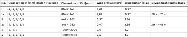
Table 2 Comparison of utilization (Ed / Rd) for examples - Full size table
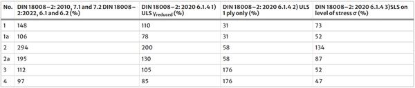
Looking at the results one can see, that already 1st step according Sect. 6.1.4 1) reduces the utilization remarkably, especially for formats lines 1 to 2a with high IGU-related climatic loads. It is obvious, that also for these combinations, the 2nd step assuming breakage of all thinner panels according to Sect. 6.1.4 2) has the largest effect. For formats with lower IGU-related “climatic loads” (see lines 3 and 4) this 2nd step makes no sense, effect of double or triple IGU can be seen. Lines 1a and 2a show, that it often does make sense, to look at real height difference ΔH from production to installation instead of taking the standard values from the code, this can remarkably reduce such permanent loads.
To sum up, the alternative procedure for design of IGUs with possibility to work with lower safety enables to realize glass setups with annealed glass instead of tempered glass and by this safe embedded energy and carbon— but if number of broken elements increases, this in the end might be a gain on the short run only. Design of IGU was and will be an interesting field, now opening additional degrees of freedom to be used responsibly.
4 Point fixed glazing
4.1 General
For thermally toughened and heat strengthened glass minimum dimensions for edge and hole spacing are defined in the product standards for toughened glass. As no sufficient knowledge about quality of prestressing in area of holes was available, (DIN 18008–1: 2010) Sect. 10.2.3 as well as (DIN 18008–1: 2020) Sect. 10.2.3 requires to assume the strength of the respective base glass to be used for the load-bearing capacity verifications if the distances are less than 80 mm, i.e. the positive effect of the thermal prestressing cannot be used. The latest research results (Efferz et al. 2023) showed that measurements and objective evaluations of anisotropy can be used to make statements about the state of prestressing on the glass surface—and thus to be able to reduce the minimum distances from 80 to 50 mm in (DIN 18008–3: 2023) Sect. 5.5 without reducing the strength.
4.2 Flush point fixings in countersunk bore holes
Starting from a generic requirement for a proper modelling of point fixed glazing using FEA in earlier code (TRPV 2006) the respective information in (DIN 18008–3: 2013) was more precise: values for material (Annex A) as well as a reference model to check users modelling quality was presented in an (Annex B). This was restricted to cylindrical bore holes – and because lack of similar information for conical drillings flush point fixings were not included in (DIN 18008–3: 2013).
Since the publication of the currently introduced (DIN 18008–3: 2013), new research results (Herrmann 2016; Seel 2016) have been developed in the area of point fixing, which allow for more precise mathematical mapping of point fixings, for example with regard to the effect of preload or friction. In addition to the refinement of calculation models, conical bores and thus flush point fixings are to be taken into account in the future as a significant extension in addition to point fixing in cylindrical bores, see Fig. 1, top. With regard to the geometry (see Fig. 1 lower), only the most common countersink angle of 90° is regulated, the minimum countersink depth s is 4 mm, whereby the ratio of countersink depth s to disk thickness t should be between 0.2 and 0.8.
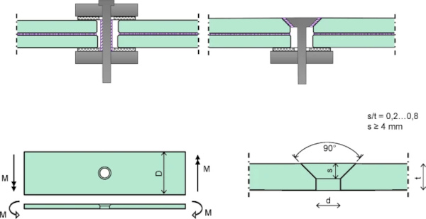
Compared to point fixings in cylindrical bores, countersunk point fixings are more sensitive and more complex in terms of computational modelling. Therefore, the corresponding (DIN 18008–3: 2023) Annex B with notes on verification in the bore area of finite element models is adapted or extended. For this purpose, a modified geometry of the known reference case “plane plate with central hole under boundary moments” is included with the corresponding solution (see Fig. 1, lower).
Due to the partially conical glass bore in particular, modelling in the thickness direction is also absolutely necessary here. Under the boundary conditions that, on the one hand, a favourably acting shear connection of an interlayer must not be applied and, on the other hand, the geometric conditions, especially in the area of the countersunk point fixing and the hole must be mapped undistorted, a (reduced) ideal modulus of elasticity should be calculated for the monolithically assumed laminated safety glass instead of an equivalent thickness. For practical application, the corresponding formulas for determining the equivalent modulus of elasticity and for evaluating the calculations are provided in the code.
Based on (Lama 2021), the simplified procedure contained in (DIN 18008–3: 2023) Annex C for the verification of the load-bearing capacity and serviceability of point-supported glazing could be extended. This is an important contribution to the acceptance of this construction method, particularly because of the countersunk head supports in conical holes, which are considerably more complex to model than plate supports with cylindrical holes. Even without special software and many years of experience with complex modelling, results that are on the safe side can be achieved with the appropriate basic knowledge.
For cylindrical holes, the maximum stress at the hole can be calculated by using variables as given in Fig. 1 with the following formulas:

where

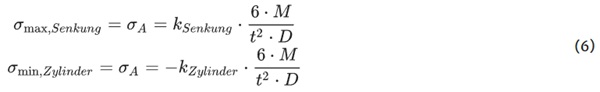
For conical drillings the situation is far more complex, the following equations can be used to calculate maximum tensile stress on upper surface near sunk hole σmax,Senkung and maximum value of compressive stress on lower surface at cylindrical part of hole σmax,Zylinder. The factor ksenkungand kzylinder depend on a/t and d/t and are given in a table of one page, ranging from 1,598 to 1,722 for ksenkung and 1,862 to 2,150 for kzylinder.
In the same way as the verification model in (DIN 18008–3: 2023) Appendix B is expanded, also the simplified method in (DIN 18008–3: 2023) Annex C for calculation of glass stress of panels supported by flush point fixings in conical-cylindrical holes is expanded. Due to higher complexity, compared to formulas for classic point fixings in cylindrical holes, the number and length of formulas grew.
5 Balustrades and anti-drop glazing
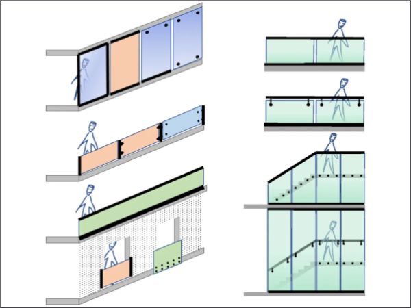
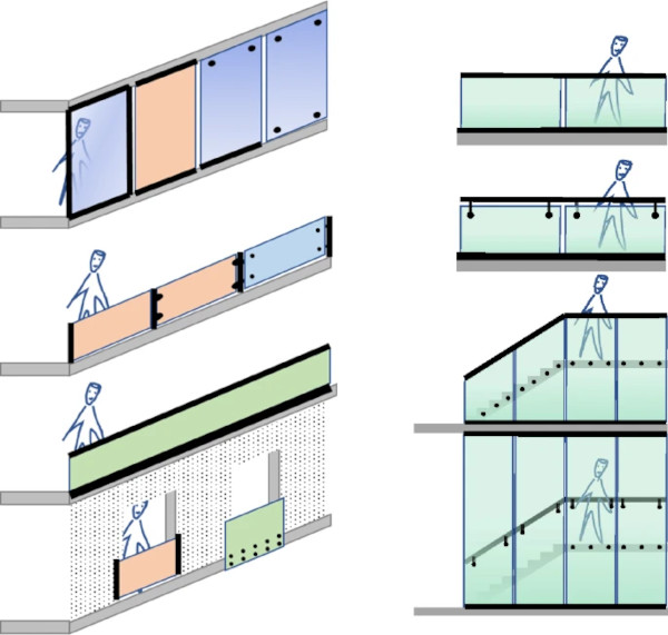
The classification of barrier glazing into categories in the updated version of (DIN 18008–4: 2023) is consistently based on the type of transfer of barrier loads; for category B, the restriction to glass clamped at the bottom has been removed.
For category A, the fall-protection function and the transfer of the barrier loads to the support are thus assumed solely by the glass element. The subdivision into subcategories A1, A2 and A3 allows further differentiation, applications A2 are covered with the update, see Fig. 2 left. Category B glazing must consist of at least two glass elements, individual glass elements are connected by a continuous handrail; if individual glass elements fail, barrier loads are transferred to neighboring supporting elements by the handrail. As a new option, for Category B it is no longer mandatory that static system is cantilevering panes supported at lower edge but by all combinations of linear or point supports are possible for fixing of glass panes as well as handrail, see Fig. 2 right. Category C still includes only infill glazing.
In the course of the verification of fall-protection glazing, limit states of the load-bearing capacity for static and impact-type actions must be carried out. In any case, design has to be verified for intact situation. Depending on the edge protection different scenarios of breakage have to be assumed: with sufficient edge protection, only one glass ply facing inwards has to be assumed broken whereas for not protected glass edges the two outside layers of laminated safety glass have to be assumed as broken and by this not existing for calculation. Reduced loading can be assumed for these accidental situations—for static calculation by respective partial safety factors as well as for impact testing by reduced pendulum falling height. Lower requirements exist for Category C and A1. LSG consisting of more than two panes of glass may in future represent economic alternatives due to the limitation of the glass panes to be assumed as failed.
Overall, the scope of application has been considerably extended by expanding the categories and differentiating the verification procedure. Unfortunately, the planned extension of the tables of already verified constructions on the basis of existing test certificates could not be implemented.
A clear presentation of the verification procedure for barrier glazing in the form of three flow charts, taking into account the different categories and design and test scenarios, helps understand principle behind and supports a correct application.
6 Conclusion and outlook
After more than a decade of application, (DIN 18008–1, -2: 2010, DIN 18008–3, -4, -5: 2013) was updated to give credit to developments in technological and scientific field as well as upcoming challenges. Overall, the field of application covered by the code is widened, more economic glass structures can be designed within the code. After implementation of Eurocode Design of Glass Structures in the future, the national design code DIN 18008 will continue to specify construction and application details, bringing together the favourable elements from European and national codes.