Authors: Markus Feldmann, Maximilian Laurs, Jan Belis, Nebosja Buljan, Annie Criaud, Eric Dupont, Martina Eliasova, Laura Galuppi, Paavo Hassinen, Ruth Kasper, Christian Louter, Giampiero Manara, Anne Minne, Tim Morgan, Gabriele Pisano, Mauro Overend, Gianni Royer-Carfagni, Jens Schneider, Gregor Schwind, Christian Schuler, Geralt Siebert & Anna Sikynova
Source: Glass Structures & Engineering | https://doi.org/10.1007/s40940-023-00219-y
Abstract
Since the beginning of 2021, CEN/TS 19100 Design of Glass Structures has been available in its first three parts. The fourth part is expected soon. This Technical Specification of the European standards organisation CEN is as a pre-standard of a corresponding future Eurocode. These documents constitute the first ever comprehensive design code for the entire structural glass engineering field on the European market for the first time. In addition to a clear outline, the Technical Specification has been drafted to be compatible with EN 1990 “Basis of Design” and to address glass-specific design matters, particularly related to robustness and redundancy. Although the standard still has the status of a CEN/TS, thereby allowing the European nations the option of whether to introduce it, either in full or in parts, it already contains national openings through which the European countries can adapt the design results to their own safety level by National Determined Parameters (NDPs). Such an approach already anticipates the future Eurocode, which is expected to be published as EN 19100—Design of Glass Structures. This article provides some context on the history and concept behind the new documents and gives an overview of the design rules and the corresponding technical background of the different parts of CEN/TS 19100.
1 Introduction
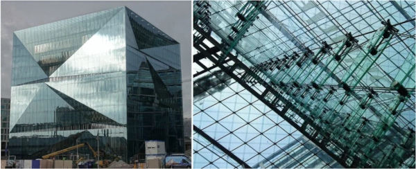
Glass plays an ever-increasing role in modern buildings, whether that be in applications allowing daylight to flood interior spaces, or aesthetic exterior design or sustainable façades, as indicated in Fig. 1. The wide use of glazing materials was recognised by the European institutions some time ago (Feldmann et al. 2014). Standards relating to glass products include construction product standardisation. On the other hand, there are standards covering the design of glass structures. They should present the latest technical progress for a problem-free realisation and seek to promote consistent safety levels. Such standards also harmonize the design methods and level of safety enabling the use of advanced numerical methods.
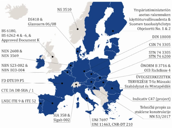
Historically, there have been a multitude of different national regulations relating to glass in building, Fig. 2, some of which are contradictory, incomplete, outdated, or not corresponding to the European basis of design of EN 1990 (2010). This situation has often resulted in structural glass designs which can only be realised with special approvals, making the design process inefficient and the construction of especially large glass structures comparatively risky. Such a situation has hindered technical progress, the economic development of the sector and the free trade in services and indirectly in goods.
The existence of such a multitude of different approaches within the market encouraged a more pan-European approach in structural glass design, similar to what has existed for other construction materials since the 1990s. With initial discussions and preparatory measures beginning in 2006, the specific mandate M/515 (2012) was issued in 2012 by the European Commission for a new generation of Eurocodes including the creation of a new Eurocode for the Design of Glass Structures.
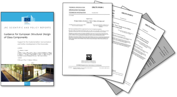
The project was split into three phases. In the first phase (Task I), a JRC Scientific and Policy (SaP-)Report “Guidance for European Structural Design of Glass Components” (Feldmann et al. 2014) was prepared giving an overview of the state of the art on glass design in order to identify the necessary technical points of the future standard and to propose the most appropriate structure for such a document, Fig. 3. This work was completed when the report was published in 2014 by the Joint Research Centre of the European Commission (JRC, Ispra). Subsequently, Working Group 3 (WG3) of CEN/TC250 was given the status of subcommittee (CEN/TC250/SC11), which was necessary to enable such a committee to make its own technical decisions for further standardization work. In parallel, CEN/TC250/SC11 got green light to produce a pre-standard in the form of a Technical Specification (CEN/TS) as a forerunner of a future Eurocode. After completion of the second phase (Task II) with the production of CEN/TS 19100—Design of Glass Structures (2021) (hereafter also referred to as “CEN/TS”) in its first three parts, Fig. 3, a subordinate working group was added as CEN/TC250/SC11/WG1. The third phase (Task III), in which the Committee is currently working, is the conversion of the CEN/TS to a Eurocode.
The present article provides an explanation of the content, the technical rules and the corresponding technical background of the different parts of CEN/TS 19100.
2 Concept and structure of CEN/TS 19100
The design and structuring of the outline and content of the CEN/TS sought to address three key points:
- Inclusion of as many relevant design aspects as possible (being typical for modern glass construction)
- Robustness and redundancy related design and detailing, allowing for the brittleness of glass which had not previously been considered in the codes for the classical construction materials, Sect. 3 of this article
- Compatibility with safety and reliability requirements of the Eurocode suite as laid down in EN 1990 (2010) including the reference to actions (loadings) as given e.g. in EN 1991-1-1 (2009) or EN 1991-1-4 (2010).
These requirements for the design of structural glass products were respected and considered as the prevailing prerequisites when producing the TS.
For example, in terms of loadings, EN 1991 does not specify rules and parameters for determining the internal cavity pressure and corresponding combinations with other actions for insulated glass units. CEN/TS 19100 addresses this omission.
Nevertheless, due to the tight time schedule and limited resources, not all relevant design aspects were addressed within the CEN/TS. For example, cold bending, buckling curves and other design aspects will be brought into the document at the Eurocode stage, Sect. 3.8 of this article. Moreover, there were some formal points in terms of compatibility with the structure of ENs and of the Eurocodes as agreed on CEN- and on CEN/TC250-level, which have influenced the work in its current form.
With regard to the structure of the CEN/TS, Fig. 4, the model structure of the other Eurocodes could not be adopted completely. Rather the approach needed to be oriented towards the typical requirements of glass construction. So, from the beginning it was clear that crucial glass related issues would need to be added to the field of basis of design-items which are not considered in EN 1990 (2010), as they are specific to glass construction. Taking into account the materials (the properties of glass and plastics, the relation to product codes, etc.), the resulting design principles associated with the extreme brittleness of glass and special assessment techniques for safety in glass, it was decided at an early stage to regulate the two fundamentals “materials” and glass related “basis of design” in a separate, and indeed first part of the CEN/TS (2021).
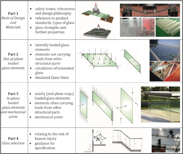
For the second part (part 2) (2021) the decision was taken to cover the design of common glass structures, which are laterally loaded, i.e. out-of-plane. This document part also covers the design of commonly used supports (i.e. continuously supported glazing along their edges, point supported glazing and cantilevered glazing, restrained at one edge) as well as issues around verifying laminated glass, Insulated Glass Units, deflections and vibrations, Sect. 3.
When considering in-plane loaded glass components, it was agreed to regulate such components in a separate third part (part 3) (2021) and not together with the more typical laterally-loaded construction elements. It was recognised that in-plane loaded components are often integrated into the primary structure in terms of overall performance and stability. However, research into the corresponding limit states and related safety assessment concepts of such structural glazed elements are relatively recent. With a separate part for the design of glass components mainly loaded in-plane, one can accommodate countries that want to include the content of the first two parts but not that of the third part of CEN/TS in their national package of binding design rules.
In contrast to the engineering nature the design rules included within the first three parts of the CEN/TS, there is the parallel and equally important issue of rules for an appropriate glass selection relating to the risk of human injury. The aspects of safety in use (not to be confused with structural safety) are regulated in Europe via national codes which are often linked closely to the state legal system. Such rules are and will be difficult to implement at a European design standard level.
To address this challenge, the fourth part provides information about the glass selection relating to the risk of human injury, thus, providing guidance for the specification of glass products in typical applications. It is envisaged that the fourth part will continue with the status of a CEN/TS with a significant lower normatively binding character even when the other parts will have been converted into a Eurocode and introduced across the European countries.
While the first three parts of the TS have achieved the necessary support in the Formal Vote and have already been published, CEN/TS250/SC11 is shortly to submit the fourth part to the Formal Vote procedure, after which the publication of the CEN/TS can also be expected.
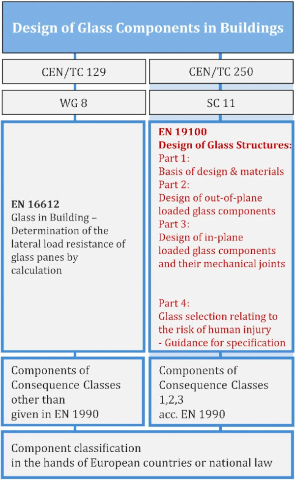
In conjunction with all of this work, there is also a relationship between the CEN/TS 19100 or the future Eurocode on the Design of Glass Structures (both of which have been or will be prepared under the design-oriented CEN/TC 250) and the existing European Standard EN 16612 (2019), which was prepared by the product-oriented CEN/TC129 committee. When considering the relationship between these two types of standards, it should be remembered that (a) the aim was to achieve the smoothest possible transition of the design results between the codes and (b) it was necessary to clarify the application areas of different standards. With regard to the first issue, an explanation of how this has been achieved is provided in Sect. 3.3. For the second issue, it was agreed, that the CEN/TS or the future Eurocode is dedicated to cases where countries decide that glass components fall under rules of EN 1990 (2010) where a component needs to be classified according to the Consequence Classes 1, 2 or 3, whereas EN 16612 (2019) will typically cover lower classes, Fig. 5.
3 Technical content of CEN/TS 19100
3.1 Conceptualization, limit states and actions
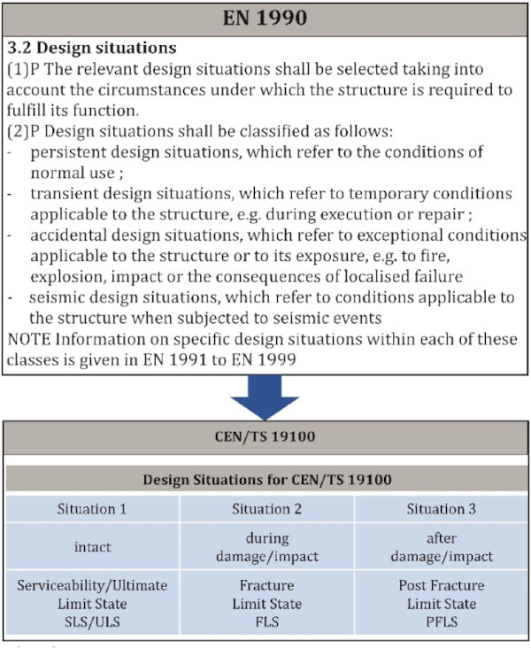
When drafting the framework for the standard, it was obvious that for glass construction, in addition to the usual design situations in which the structure is intact, there are also cases to be considered in which the structure breaks or is (partially or fully) broken. This characteristic is in distinct contrast to other building materials. The consideration of different design situations is provided in the rules of Sect. 3.2 of EN 1990 (2010), which was applied when preparing CEN/TS 19100. In pursuing this strategy, it became necessary to introduce two further limit states reflecting the additional design situations during and after breakage, namely the “Fracture Limit State” (FLS) and the “Post Fracture Limit State” (PFLS), respectively. In terms of character the additional limit states clearly belong to the genus of “Ultimate Limit States”, but they were given their own names because of their significance and importance in glass design, Fig. 6.
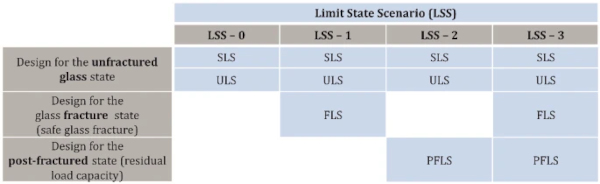
Based upon the differing historical approaches to glass products and design, it is predictable that the same or similar glass components in the same or similar buildings will be treated differently in the various European countries with regard to their safety requirements. For this reason, the classification under which a glass component is to be verified, and in which limit state, in addition to the classification in the various Consequence Classes (CCs) according to EN 1990 (2010) and the selection of the safety factors, is prerogative of the national states through corresponding formulations in the National Application Documents (NADs). The bundling of limit states into so-called "Limit State Scenarios", as a definition of the necessary set of verifications, helps in the safety-related specification of individual glass components, Fig. 7.
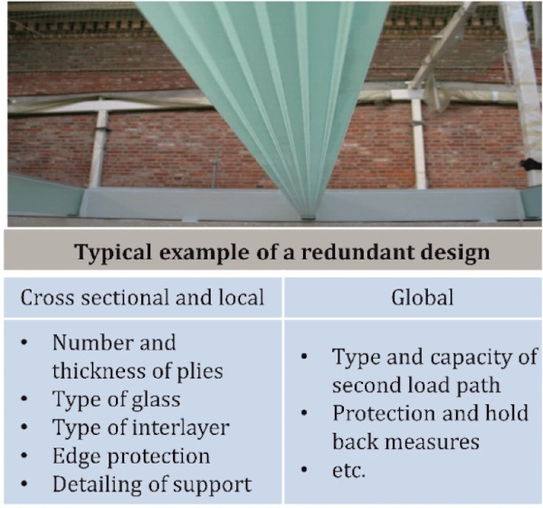
Creation of robustness and redundancy is a prevailing issue in structural glass design and is clearly reflected within the CEN/TS, ranging from the detailing over the components’ level up to the integration in the overall context, Fig. 8.
By considering these additional limit states, awareness of the necessary robustness characteristics is emphasized, which as previously stated plays a very special role in glass construction due to the brittleness of the building material.
Undoubtedly, the level of safety for glass elements that are not integrated into the structural context of the superordinate structure differ from those that are integrated into it. This is of course due to the significantly different failure consequences, Fig. 9.
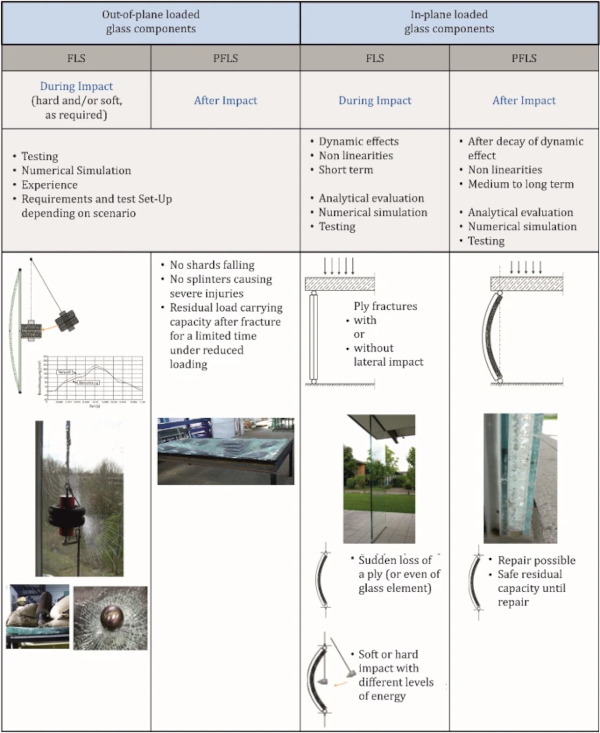
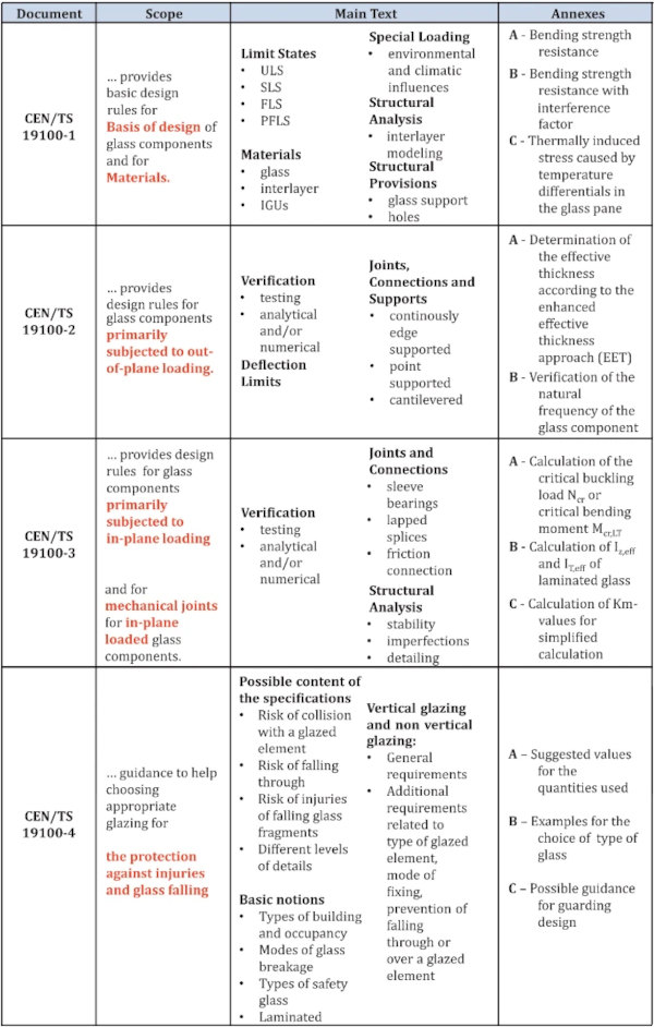
Figure 10 gives an overview on the technical topics of CEN/TS 19100 according to its different parts as explained, differentiated according to scope, main text and annexes.
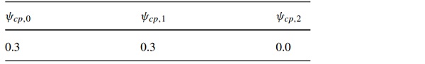
In terms of actions, in addition to the provisions of EN 1991 (2002), CEN/TS 19100 gives additional product specific advice. Especially in the case of Insulating Glass Units (IGUs), the input parameters for determining the internal cavity pressure (which is in the glass world usually called “climatic actions”, but can be confused with the other “climatic actions” as given in EN 1991 (2002)) are provided. Combination factors for cavity pressure specified by CEN/TS 19100-1 can be found in Table 1. The procedure to determine the internal cavity pressure follows the methodology as found in EN 16612 (2019). Another promising procedure that allows consideration of a wider range of geometries and loading configurations is represented by the BAM approach (Betti’s Analytical Method), see Galuppi and Royer-Carfagni (2020a), Galuppi (2020) and Galuppi and Royer-Carfagni (2020b). Such an approach may be added in the final version of the Eurocode.
Table 1 Combination factors for cavity pressures of Insulating Glass Units (IGUs) in CEN/TS 19100-1 (2021) - Full size table
In addition, to prevent thermal fracture in glass, Annex C of CEN/TS 19100-1 (2021) provides valuable information on determining thermal gradients and temperature induced stresses in glass panes, Fig. 11.
3.2 Types of glass components, glass types and other materials
As would be expected, CEN/TS 19100 addresses the European family of glass products in building, Fig. 12, using the characteristic basic material strength values provided in the product standards. With regard to basic soda-lime silicate glass, the approach starts with different types of annealed glass acc. EN 572 (2012) over heat strengthened glass acc. EN 1863 (2011) to thermally toughened glass acc. EN 12150 (2015) or even to chemically strengthened glass acc. EN 12337 (2000). In addition to the standard forms of glass substrate, CEN/TS 19100 also refers to other glass products such as borosilicate, alkaline earth silicate glass, alumino silicate glass etc. However, since these products are currently not widely used in construction, only the standards are referenced, without providing further values.
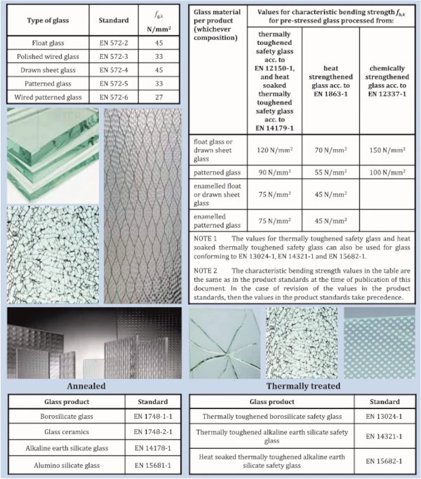
Products treated in CEN/TS 19100 are flat glass either as monolithic, laminated, insulating glass assemblies or combinations thereof, comprising the usual edge treatment types. Design of acrylic glass is not covered.
3.3 Design bending strength
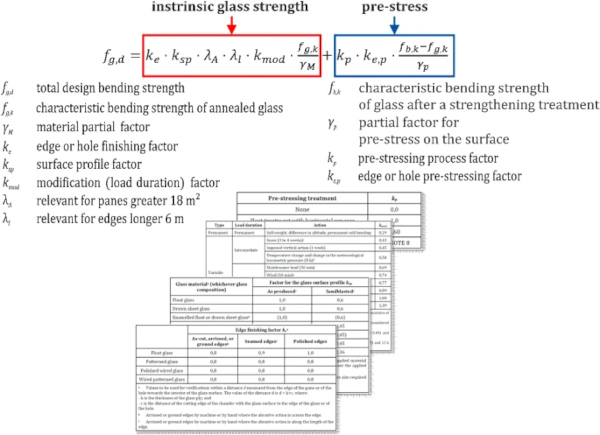
Perhaps no topic is of more interest to the glass designers’ community than the determination of the resulting design glass bending strength. Based on the material strengths of the product standards, corresponding calculation rules have been created in Annex A of CEN/TS 19100-1 (2021) for the areas of surface (Laufs and Sedlacek 1999a; b; Veer et al. 2009; Pisano and Royer-Carfagni 2015), edge (Kleuderlein et al. 2014; Vanderbroek et al. 2012, 2014), hole (Schneider and Wörner 2001; Schneider 2004) and corner zones for various load application durations, dimensions, edge qualities and degrees of prestress, Fig. 13. Within this approach, the intrinsic strength component is separated from the prestress component. The procedure and concept correspond to that of EN 16612 (2019). CEN/TS 19100-1 (2021) is in this respect compatible and can be regarded as the corresponding extension.
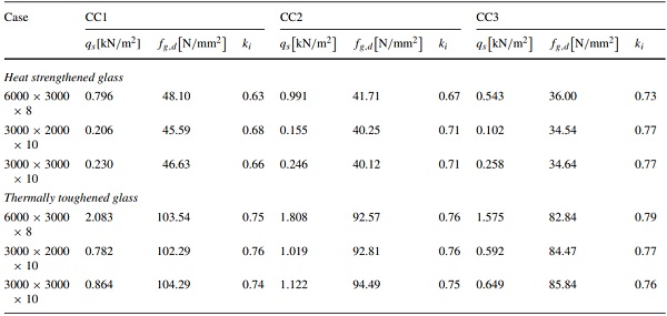
Although this method of strength determination was considered state of the art a few years ago, further developments can be observed in certain areas today. In particular, the evaluations and comparisons with tests are reported to have revealed conservatism, which is due to the fact that the probability of poorer surfaces or unfavourable scratch orientation does not coincide (or only to a reduced extent) with the probability of poorer intrinsic strengths (Pisano et al. 2019a). This leads to an interference factor ki allowing for a more favourable strength. The factor ki can then be introduced in Annex B of CEN/TS 19100-1 (2021) via the NAD. The calculation of this improved strength prediction is not very different from Annex A. However, up to now, the new model of Annex B does not specify numerically the improvements through ki, which differ according to glass type. According to the CEN/TS, such values have to be determined in individual cases or specified separately in the countries. But corresponding numerical values have already been worked out for the future Eurocode version. Background can be found in (Pisano et al. 2022) and in Fig. 14 and Table 2, according to Pisano et al. (2022).
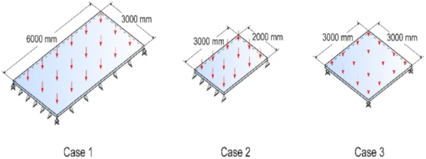
Table 2 Calibrated values of the interference factor ki for the families of structures shown in Fig. 14 Case of snow action - Full size table
It should be understood, that when CEN/TS 19100 refers to a "bending strength", this, also comprises the strength both under bending or under normal force (as well as combinations thereof). This considers the progress that we now also deal with in plane loaded structures (see CEN/TS 19100-3 (2021)).
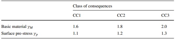
With respect to the design level of resistances compared to the characteristic level, different investigations have been performed, associated with discussion with CEN/TC250/SC10 being responsible for the evolution of EN 1990 (Eurocode). For the basic cases, the safety coefficients as given in Table 3 could be derived for the different consequence classes (CCs). There, the safety coefficient γm = 1.8 for CC 2 referring to a safety index of β = 3.8 could be confirmed by several statistical approaches. Once with a FORM (First Order Reliability Method) analysis on the resistance side with αR (FORM sensitivity factor for resistance), which assumes a log-normal distribution for the strength (Wellershoff 2006), and once with a Weibull distribution based on a fully probabilistic approach including random scratch orientation and statistical load modelling using extreme value distribution (Ballarini et al. 2016; Pisano et al. 2019b).
Table 3 Safety coefficients γM and γp for different consequence classes - Full size table
3.4 Design of laminated glass
When dealing with the developments of interlayer technologies and their variety of properties, the consideration of the interlayer shear coupling effect is one of the key factors for reducing mass in glass design, Fig. 15.
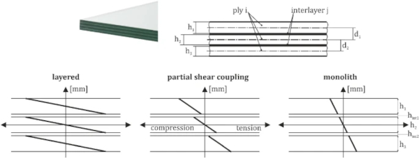
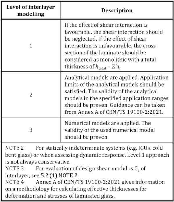
Shear coupling effects may be expressed in terms of time and temperature. In simple terms, CEN/TS 19100 allows for three different levels of design: (1) full or no shear coupling, (2) analytical models for determination of the effective mechanical properties of the elastically layered cross sections and (3) numerical modelling, Fig. 16.
For what concerns IGUs under normal circumstances, the nature of cavity pressure and load coupling in the cavity requires particular care when considering what the most relevant case might be, i.e. whether the stiffer or softer behaviour of the interlayer has to be considered in which combination of that of the other pane, i.e., whether the higher or lower value for the shear modulus of the interlayer needs to be taken. Of course, this requires the availability of corresponding reliable material values at both sides of the distributions. However, since this is a very hard task, we cannot expect a straightforward solution from the plastics material side, this will take some additional time even beyond the introduction of the Eurocode. It should also be remembered that the safety impact, due to the part of the resistance is not as high as e.g. that of the glass strength itself.
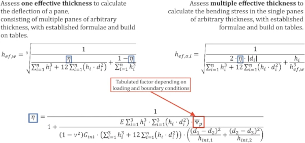
Although standards should not normally display the characteristics of a textbook, CEN/TC250/SC11 concluded that in the case of the stress and deformation determination of laminated glasses, assistance should be provided in accordance with the latest results for analytical calculation. Such an approach provides an alternative to the laborious and demanding simulations with Finite Element Modelling (FEM). This can now be found in Annex A of the second part of CEN/TS 19100 (2021).
The theory is based on the Enhanced Effective Thickness theory (EET) (Galuppi et al. 2013, 2014; Galuppi and Royer-Carfagni 2014) as an improvement compared to the Bennison-Wölfel method (Wölfel 1987). It provides comparable results to EN 16612 (2019), but now includes a considerably wider range of applications with a significantly wider range of boundary conditions is on offer. In this regard, the calculation formulas refer to double or triple laminated glass for different types of loading and storage conditions for laterally loaded beams and plates. Figure 17 shows examples of the calculation formulas.
3.5 Topics on in-plane loaded glass components, enhanced robustness, stability and special joints
The transparency and translucency of a structure is undoubtedly increased when glass components are statically integrated into the superordinate structure, e.g. in beams, walls or shear panels. A characteristic of these components is that in addition to the transverse load, they are subject to considerable, often predominant, longitudinal, i.e. in-plane, stress. For this reason, part 3 of CEN/TS19100 (2021) is dedicated to in-plane loaded glass elements.
In such circumstances, the prerequisite robustness and reliability of such glass components cannot be achieved by adopting the simple rules for FLS and PFLS as provided for the subordinate transversely loaded components covered in CEN/TS 19100-2 (2021). This approach applies particularly to those components that are part of the load-bearing system of the overall structure. As a rule, such components are manufactured from sufficiently multi-layered laminated safety glass to achieve sufficient robustness and additionally, there should be an alternative load path in case of collapse of a whole glass element. So, in addition to CEN/TS 19100-2 (2021), in CEN/TS 19100-3 (2021) there is further advice provided concerning for the enhanced requirements for theoretical and experimental assessment.
It should be noted that, it is common that potentially destructive component tests cannot be carried out in the building itself since the remaining component would then be pre-damaged and difficult to replace. For this reason, such destructive components tests are typically executed elsewhere (e.g. in a laboratory or workshop) on specially-prepared, additional test specimens. However, in some special cases CEN/TS 19100-3 (2021) also permits verification in FLS and PFLS without testing.
Apart from the load introduction at the edges of the components, which beside basic verification formulae has to be solved rather constructively, rules are given for the assessment of stability in both intact and broken states, which is of particular importance in the design and for the dimensioning of structural glass components. For instance, if glass panes (glass plates) are loaded in-plane, they can fail due to out-of-plane deformation (flexural buckling (Langosch and Feldmann 2016), lateral torsional buckling (Luible and Crisinel 2004; Kasper et al. 2007; Amadio and Bedon 2011) or plate buckling (Luible and Crisinel 2005)), depending on the degree of slenderness, geometric imperfections (Belis et al. 2011) and edge conditions, or partial fracture.
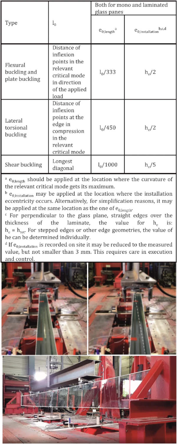
Part 3 gives rules for the equivalent imperfection to be used when verifying such components subjected to in-plane loading, for the occurring stability phenomena. The equivalent geometrical imperfections should be applied at the largest ordinate of the eigenmode deformation in terms of curvature, Fig. 19. In addition to the imperfection values of the component itself, installation imperfection values have to be considered, which may vary from the level of execution control.
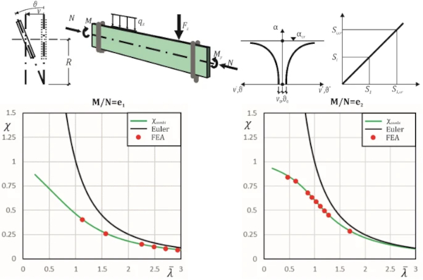
In the future Eurocode version, we are awaiting consistent buckling curves for such cases, which for simple cases will make the FEM verification superfluous and thus facilitate the stability verifications, Sect. 4 of this article.
In addition, for thermally toughened glass, rules are provided to consider safety in the event that a glass ply suddenly breaks, for whatever reason, and a short-term stress-increasing impact effect is induced in the remaining intact cross-section.
But it is not only the art of designing and dimensioning the components themselves which is covered in the standard. Part of the repertoire of a skilled designer must also be to appropriately engineer the connections to and between structural glass elements. In the case of in-plane loaded elements, jointing of such components comprised of glass has rarely been addressed until recently. This situation has changed by further research work (Baitinger and Feldmann 2010; Nielsen et al. 2010; Watson et al. 2013).
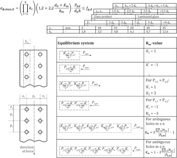
For this reason, the design of "special joints" has been included within of part 3 of CEN/TS 19100. “Special connections" are those that allow the transfer of internal forces in the plane of the glass from one glass component to the other. Such methods would include jointing with bolts in shear, adhesive bonded joints or clamped joints using friction for the shear transmission, and should not be confused with “normal” supports, like point fixings (Graf et al. 2004) that are dealt with in CEN/TS 19100-2 (2021). In simple terms, it is recommended that such jointing systems should be designed and verified by aids of FEA (Finite Element Analysis), but for some configurations, CEN/TS 19100 – 3 gives analytical design methods enabling quick verification of the structural layout, Fig. 18, in addition to construction detailing recommendations.
3.6 Serviceability issues
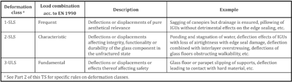
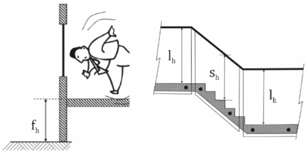
Whilst in some countries and in some other industries it is common to exclude limit values for deformations from a calculation specification, such limits have been included in the CEN/TS with good reason. In fact, when dealing with glass products, the limit value for deformation can be different depending on the type of glass component present. This issue is more pronounced for glass than for other building materials for reasons of comfort and aesthetics, as well as functional limits of deflection (Fig. 19). For example, the deformation limits of insulating glass units are present to protect the air tightness of the cavity, which is a functional requirement, Fig. 20.
Excessive deflection can also result in glazed products disengaging from its supports, which is in turn a requirement that affects the ULS (load-bearing capacity). For this reason, a sufficiently large glass bite is necessary, which is regulated in the CEN/ TS. In addition to these specific limits, Fig. 21, simplified rules for quick design check have been provided. Furthermore, rules for the calculation and determination of limit values for permissible vibration frequencies (dynamics) have been provided in Annex B of part 2 of CEN/TS 19100.

3.7 Part 4 of CEN/TS 19100
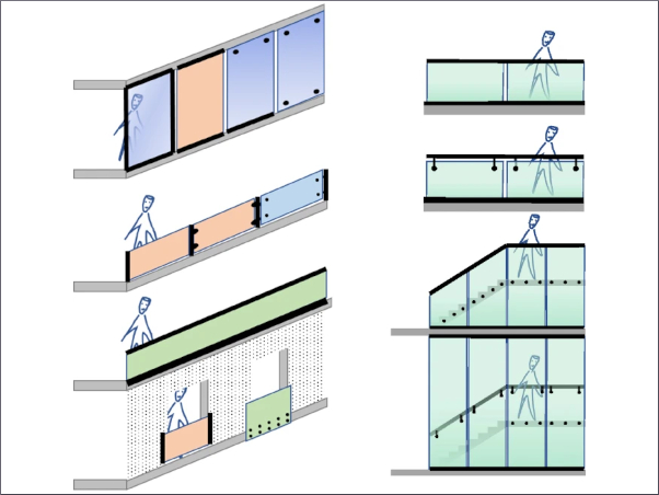
Part 4 of CEN/TS 19100 is a special feature which differentiates this suite of standards from the “classic” engineering design issues related to calculation or testing. As defined in its scope, part 4 is intended to serve as guidance for the development or the improvement of rules intended to assist in selecting the appropriate glazed product for protection against injury and falls. These rules can be regarded as specifications which might cover national regulation, national standard, recommendations from a professional association, requirements for a particular project etc. Thus, part 4 also includes a special section which presents suggestions for a possible content of such specifications. Part 4 deals with the safety of people when considering.
- The risk of injury in the event of a collision with a glazed element, e.g. a partition,
- The risk of falling through or over a glazed element, e.g. a balustrade, and,
- The risk of glass fragments falling from height onto people who have not caused the breakage, e.g. an overhead glazing.
The advice distinguishes between vertical and non-vertical glazing, function, critical zones, type of glazed element, glass type and dimensions of the glazed element, mode of fixing, arrangement and geometry of the surrounding structure, type of collision or fall, injury consequences etc. Figure 2 provides a summary of basic European standards which already exist e.g. DIN 18008 (2020), FD DTU 39 P5 (2017) or NBN S23-002 (2020).
In addition, Part 4 includes 3 annexes. Annex A suggests ranges of geometric dimensions and environmental geometries within which the risk of injury is considered acceptable. Annex B deals with recommendations concerning the choice of glass type, and Annex C gives possible guidance for guarding design (see examples given in Fig. 22). All annexes are informative.
The current intention is that Part 4 will not be converted into a Eurocode in the future, as its content is to be understood in the sense of "safety and accessibility in use"—issues (basic requirement 4 for construction works of the Construction Product Regulation (CPR)). The subject matter of Part 4 does not include "mechanical resistance and stability " (basic requirement 1 for construction works of the CPR), as is the case for the other parts of the CEN/TS. Issues relating to “safety in use” are difficult to include in a Eurocode, because of the variety of legal systems in use within the individual nations across Europe. For this reason, it was decided that this kind of regulation should be left in the status of recommendations, i.e. a CEN/TS, both now and in the future.
Finally, it should be acknowledged that the choice of glass type is usually one of the first steps of design, and is a task which should be completed in close cooperation with the architect. For this reason, the subject matter contained in Part 4 of the CEN/TS is particularly important—perhaps, more than one might think at a first glance.
3.8 Remaining items for the eurocode
It was always the intention that the CEN/TS be drafted in the same style and with the same content as an EN standard. For this reason, the Eurocode version will be very similar to the CEN/TS. Nevertheless, some revisions and additions are expected. Such revisions and additions, whether based upon lessons gleaned from applications in trial-use phase, or from the points that the committee CEN/TC250/SC11 has already identified itself are expected to include:
- The determination of ki. The underlying research for this has already been completed, see above,
- Clearer choice of the kmod value to determine the bending strength, especially for the action of wind in the range of duration between 3 s and10 min,
- An Annex on design recommendations for cold bent glass,
- Buckling curves for flexural buckling and lateral torsional buckling and combinations thereof for simple loading cases and simple aspect formats of glass panes, Fig. 23, and
- Improved methods for the evaluation of load sharing in IGUs.
It is likely that other revisions and subject matter will be included. Of course, as is the case for other European standards (ENs), after completion of the Eurocode, further developments and improvements that become apparent will be codified and taken up by issuing respective amendments. To this end CEN/TC 250 has provided a special “systematic review” for all Eurocodes. A rough timeline covering future work up until the standard is available as a Eurocode is outlined in the following section.
4 Concluding remarks and outlook
This paper provides some history relating to the conceptualization of the Technical Specification CEN/TS 19100 part 1 to 4, and summarises some of the most important rules and technical background of the code. The structure and compatibility of the new CEN/TS with the other Standards in the Eurocode suite has been explained, including the relevance to EN 1990 (2010), as well as the relationship with European product standards. Furthermore, the article shows the necessity for limit state considerations including but not limited to intact states and how to include this in European standardisation.
Most of the relevant technical design topics and requirements for standardisation in modern glass constructions are addressed within CEN/TS 19100. However, a few are currently still under consideration and are expected to be incorporated in the future Eurocode.
The CEN/TS 19100 is intended for trial use in glass design. The feedback from industry and the design community will help to improve the document during its conversion into a Eurocode. To this end, the corresponding technical works are under way and the topics, which the committee CEN/TC250/SC11 is still discussing, have been summarised.
It is expected that the technical work described herein will be finalized by the end of 2023 so that the preparation of the enquiry phase can start as planned in 2024. After incorporation of the comments from the countries, further formalities and translation works, and after Formal Vote we are hopeful that the Eurocode will be published in 2026. At that point it will be the responsibility of the European countries to prepare their National Application Documents (NADs), to ensure that nothing stands in the way of the respective national standards being withdrawn.
Data availability
Data sharing not applicable to this article as no datasets were generated or analysed during the current study.
References
Acknowledgements
The authors would like to express their sincere thanks to the European Commission and CEN/TC 250 for their confidence in the preparation of CEN/TS 19100 within mandate M/515, in particular for their financial support. Furthermore, the following persons are to be thanked for their valuable contributions in the discussions leading to the preparation of CEN/TS (in alphabetical order): Mascha Baitinger (Contura Ingenieure, Mainz); Luigi Biolzi (Politecnico Milano); John Colvin (Shelmersdale); Graham Dodd (ARUP, London); Michel Dubru (Glass for Europe, Louvain-la-Neuve); Jo Joosten (kenniscentrum glas, Gouda); Ron Kruijs (Glasimpex Schiedam); Nils Landa (Bolseth Glass, Sandane); Peter Lenk (ARUP, London); Andreas Luible (Hochschule Luzern); Kent Persson (Lund University); Vlatka Rajcic (University of Zagreb); Paolo Rigone (Politecnico Milano); Daniela Schön (DIN, Berlin); Wim Stevels (Eastman Chemical Company, The Hague); Panu Visa (Lumon, Kouvola); Norbert Wruk (Pilkington, Cologne); Anke Zillmann (DIBt, Berlin).
Funding
Open Access funding enabled and organized by Projekt DEAL.
Author information
Authors and Affiliations
- Institute of Steel Construction, RWTH Aachen University, Mies-Van-Der-Rohe-Straße 1, 52074, Aachen, Germany - Markus Feldmann & Maximilian Laurs
- Department of Structural Engineering and Building Materials, Ghent University, UGent Tech Lane, Lab. Magnel-Vandepitte, Technologiepark-Zwijnaarde 60, 9052, Ghent, Belgium - Jan Belis
- RI ISA d.o.o. Rijeka, Permasteelisa Group, Kapitanovo 25, 51000, Rijeka, Croatia - Nebosja Buljan
- AGC Glass FRANCE SAS, 114 Bureaux de La Colline, 92213, Saint-Cloud Cedex, France - Annie Criaud
- Belgian Building Research Institute (BBRI), Avenue P. Holoffe 21, 1342, Limelette, Belgium - Eric Dupont
- Faculty of Civil Engineering, Czech Technical University in Prague, Thakurova 7, 166 29, Prague 6, Czech Republic - Martina Eliasova
- Department of Engineering and Architecture, University of Parma, Parco Area Delle Scienze 181/A, 43124, Parma, Italy - Laura Galuppi
- Pontek Oy, Part of Solwers PLc, Kutojantie 2B, 02630, Espoo, Finland - Paavo Hassinen
- Technische Hochschule Köln, Betzdorfer Straße 2, 50679, Cologne, Germany - Ruth Kasper
- Faculty of Civil Engineering and Geosciences, Delft University of Technology, Stevinweg 1, 2628 CN, Delft, The Netherlands - Christian Louter
- Permasteelisa S.P.A, Viale Enrico Mattei 21/23, 31029, Vittorio Veneto, TV, Italy - Giampiero Manara
- Saint-Gobain Building Glass Europe, Boulevard Industriel, 129, 1070, Brussels, Belgium - Anne Minne
- Crossley Consult, Dunstans, Shermanbury Road Partridge Green, West Sussex, RH13 8EU, UK - Tim Morgan
- Construction Technologies Institute-Italian National Research Council (ITC-CNR), Viale Lombardia 49, 20098, San Giuliano Milanese, Milan, Italy - Gabriele Pisano
- Faculty of Architecture and the Built Environment TU Delft, Julianalaan 134, 2628 BL, Delft, The Netherlands - Mauro Overend
- Department of Engineering and Architecture, University of Parma Construction Technologies Institute-Italian National Research Council (ITC-CNR), Parco Area Delle Scienze 181/A, 43124, Parma, Italy - Gianni Royer-Carfagni
- Institute of Structural Mechanics and Design, Technical Universtity of Darmstadt, Franziska-Braun-Sr. 3, 64287, Darmstadt, Germany - Jens Schneider & Gregor Schwind
- Institute for Material and Building Research, University of Applied Sciences Munich, Karlstraße 6, 80333, Munich, Germany - Christian Schuler
- Institut Und Labor Für Konstruktiven Ingenieurbau, Universität Der Bundeswehr München, Werner-Heisenberg-Weg 39, 85577, Neubiberg, Germany - Geralt Siebert
- AGC Glass Europe, Avenue Jean Monnet 4, 1348, Louvain-la-Neuve, Belgium - Anna Sikynova
Corresponding author
Correspondence to Maximilian Laurs.
Ethics declarations
Conflict of interest
On behalf of all authors, the corresponding author states that there is no conflict of interest.